CN116145754A - Ditching machine for urban construction - Google Patents
Ditching machine for urban construction Download PDFInfo
- Publication number
- CN116145754A CN116145754A CN202310236716.0A CN202310236716A CN116145754A CN 116145754 A CN116145754 A CN 116145754A CN 202310236716 A CN202310236716 A CN 202310236716A CN 116145754 A CN116145754 A CN 116145754A
- Authority
- CN
- China
- Prior art keywords
- fixedly connected
- soil
- counterweight
- broken
- trenching
- Prior art date
- Legal status (The legal status is an assumption and is not a legal conclusion. Google has not performed a legal analysis and makes no representation as to the accuracy of the status listed.)
- Withdrawn
Links
- 238000010276 construction Methods 0.000 title claims abstract description 30
- 239000002689 soil Substances 0.000 claims abstract description 168
- 238000005096 rolling process Methods 0.000 claims description 26
- 241000124033 Salix Species 0.000 claims description 18
- 238000012545 processing Methods 0.000 claims description 8
- 230000008878 coupling Effects 0.000 claims description 6
- 238000010168 coupling process Methods 0.000 claims description 6
- 238000005859 coupling reaction Methods 0.000 claims description 6
- 230000000694 effects Effects 0.000 abstract description 6
- 238000010586 diagram Methods 0.000 description 9
- 230000003993 interaction Effects 0.000 description 8
- 238000007790 scraping Methods 0.000 description 7
- 238000000034 method Methods 0.000 description 6
- 238000009412 basement excavation Methods 0.000 description 5
- 230000008569 process Effects 0.000 description 4
- 208000012260 Accidental injury Diseases 0.000 description 3
- 230000009471 action Effects 0.000 description 3
- 238000004140 cleaning Methods 0.000 description 3
- 239000000758 substrate Substances 0.000 description 3
- 238000011161 development Methods 0.000 description 2
- 208000014674 injury Diseases 0.000 description 2
- 238000012986 modification Methods 0.000 description 2
- 230000004048 modification Effects 0.000 description 2
- 230000009286 beneficial effect Effects 0.000 description 1
- 238000005056 compaction Methods 0.000 description 1
- 238000013461 design Methods 0.000 description 1
- 238000005516 engineering process Methods 0.000 description 1
- 239000000463 material Substances 0.000 description 1
- 238000003825 pressing Methods 0.000 description 1
- 230000001737 promoting effect Effects 0.000 description 1
- 238000009418 renovation Methods 0.000 description 1
Images




Classifications
-
- E—FIXED CONSTRUCTIONS
- E02—HYDRAULIC ENGINEERING; FOUNDATIONS; SOIL SHIFTING
- E02F—DREDGING; SOIL-SHIFTING
- E02F5/00—Dredgers or soil-shifting machines for special purposes
- E02F5/02—Dredgers or soil-shifting machines for special purposes for digging trenches or ditches
- E02F5/08—Dredgers or soil-shifting machines for special purposes for digging trenches or ditches with digging wheels turning round an axis
-
- E—FIXED CONSTRUCTIONS
- E02—HYDRAULIC ENGINEERING; FOUNDATIONS; SOIL SHIFTING
- E02D—FOUNDATIONS; EXCAVATIONS; EMBANKMENTS; UNDERGROUND OR UNDERWATER STRUCTURES
- E02D3/00—Improving or preserving soil or rock, e.g. preserving permafrost soil
- E02D3/02—Improving by compacting
- E02D3/026—Improving by compacting by rolling with rollers usable only for or specially adapted for soil compaction, e.g. sheepsfoot rollers
- E02D3/032—Trench rollers
-
- E—FIXED CONSTRUCTIONS
- E02—HYDRAULIC ENGINEERING; FOUNDATIONS; SOIL SHIFTING
- E02F—DREDGING; SOIL-SHIFTING
- E02F5/00—Dredgers or soil-shifting machines for special purposes
- E02F5/02—Dredgers or soil-shifting machines for special purposes for digging trenches or ditches
- E02F5/027—Dredgers or soil-shifting machines for special purposes for digging trenches or ditches with coulters, ploughs, scraper plates, or the like
-
- E—FIXED CONSTRUCTIONS
- E02—HYDRAULIC ENGINEERING; FOUNDATIONS; SOIL SHIFTING
- E02F—DREDGING; SOIL-SHIFTING
- E02F5/00—Dredgers or soil-shifting machines for special purposes
- E02F5/30—Auxiliary apparatus, e.g. for thawing, cracking, blowing-up, or other preparatory treatment of the soil
- E02F5/305—Arrangements for breaking-up hard ground
Landscapes
- Engineering & Computer Science (AREA)
- Structural Engineering (AREA)
- Mining & Mineral Resources (AREA)
- Civil Engineering (AREA)
- General Engineering & Computer Science (AREA)
- Mechanical Engineering (AREA)
- Life Sciences & Earth Sciences (AREA)
- Agronomy & Crop Science (AREA)
- Environmental & Geological Engineering (AREA)
- Soil Sciences (AREA)
- General Life Sciences & Earth Sciences (AREA)
- Paleontology (AREA)
- Soil Working Implements (AREA)
Abstract
本发明公开了一种用于城市建设用挖槽开沟机,本发明涉及挖槽开沟设备技术领域,包括机架,机架的内表面底部且靠近右端位置设置有沟槽开设装置,机架的内表面且靠近沟槽开设装置的位置设置有碎土处理装置,机架的内表面且靠近碎土处理装置的位置设置有夯实装置,壳体滑轨的内表面滑动连接有碎土挡板,碎土挡板的外表面固定连接有受力件,碎土挡板的底部固定连接有掘土犁,碎土挡板的外表面底部设置有拨土装置,碎土挡板的外表面固定连接有推动凸起。该用于城市建设用挖槽开沟机,达到了碎土处理的效果,可及时对挖掘的碎土及时清理,并不用出现碎土掉落会沟槽塌陷的情况,减轻了人工劳动量,挖槽开沟效果好。

The invention discloses a grooving and ditching machine for urban construction. The invention relates to the technical field of grooving and ditching equipment. A crushing device is installed on the inner surface of the frame and close to the groove opening device, a tamping device is installed on the inner surface of the frame and close to the crushing device, and a crushing block is slidably connected to the inner surface of the housing slide rail. The outer surface of the broken soil baffle is fixedly connected with a force-bearing member, the bottom of the broken soil baffle is fixedly connected with a digging plow, the bottom of the outer surface of the broken soil baffle is provided with a soil pulling device, and the outer surface of the broken soil baffle is The fixed connection has push tabs. The trenching and trenching machine used for urban construction has achieved the effect of crushed soil treatment, and can timely clean up the excavated crushed soil without the situation that the crushed soil will fall and the trench will collapse, which reduces the amount of manual labor. The effect of digging and ditching is good.
Description
技术领域technical field
本发明涉及挖槽开沟设备技术领域,具体为一种用于城市建设用挖槽开沟机。The invention relates to the technical field of trenching and ditching equipment, in particular to a trenching and ditching machine for urban construction.
背景技术Background technique
城市建设是以规划为依据,通过建设工程对城市人居环境进行改造,对城市系统内各物质设施进行建设,城市建设的内容包括城市系统内各个物质设施的实物形态,是为管理城市创造良好条件的基础性、阶段性工作,是过程性和周期性比较明显的一种特殊经济工作。随着科技的不断发展,社会的不断进步,近年来城市建设的快速发展,很多城市都完成了城市区域的建设和改造工作。在城市建设过程中,需要用到各式各样的机械设备,以更好更快的完善对城市的建设。而对地面进行挖槽开沟时必不可少的一步。因此需要用到挖槽开沟设备,以代替人工挖槽开沟。Urban construction is based on planning, and through construction projects, the urban living environment is transformed, and various material facilities in the urban system are constructed. Conditional basic and phased work is a special economic work with obvious process and periodicity. With the continuous development of science and technology, the continuous progress of society, and the rapid development of urban construction in recent years, many cities have completed the construction and renovation of urban areas. In the process of urban construction, a variety of mechanical equipment is needed to improve the construction of the city better and faster. It is an essential step when digging trenches on the ground. Therefore, it is necessary to use trenching and trenching equipment to replace manual trenching and trenching.
目前,现有的挖槽开沟机对泥土开挖后,不便对碎土进行及时清理,需要人工后续处理,尤其在一些土质松软的区域,沟槽内会塌陷大量的碎土,同时挖掘上来的碎土还会掉落到沟槽内,需要再次进行清除,增加了人工劳动量。At present, after the existing trenching and trenching machines excavate the soil, it is inconvenient to clean up the broken soil in time, and manual follow-up treatment is required, especially in some areas with soft soil, a large amount of broken soil will collapse in the trench, and it will be excavated up at the same time. The crushed soil will also fall into the trench, which needs to be removed again, which increases the amount of manual labor.
发明内容Contents of the invention
为实现以上目的,本发明通过以下技术方案予以实现:一种用于城市建设用挖槽开沟机,包括机架,所述机架的内表面底部且靠近右端位置设置有沟槽开设装置,所述机架的外表面固定连接有伺服电机,所述伺服电机的输出轴通过联轴器与沟槽开设装置的外表面端部固定连接,所述机架的内表面且靠近沟槽开设装置的位置设置有碎土处理装置,所述机架的内表面且靠近碎土处理装置的位置设置有夯实装置,所述机架的外表面顶部固定连接有把手,所述机架的外表面底部安装有升降机轮,通过升降机轮将装置移动到指定的位置,此时通过伺服电机将沟槽开设装置带动进行转动,对土地进行开挖;In order to achieve the above object, the present invention is achieved through the following technical solutions: a trenching and ditching machine for urban construction, including a frame, the bottom of the inner surface of the frame and a groove opening device near the right end position, The outer surface of the frame is fixedly connected with a servo motor, the output shaft of the servo motor is fixedly connected with the end of the outer surface of the groove opening device through a coupling, and the inner surface of the frame is close to the groove opening device A broken soil processing device is provided at the position of the frame, and a tamping device is provided on the inner surface of the frame near the position of the crushed soil processing device. The top of the outer surface of the frame is fixedly connected with a handle, and the bottom of the outer surface of the frame is The elevator wheel is installed, and the device is moved to the designated position through the elevator wheel. At this time, the groove opening device is driven to rotate by the servo motor, and the land is excavated;
所述碎土处理装置包括壳体滑轨,所述壳体滑轨的外表面与机架的顶部固定连接,所述壳体滑轨的内表面滑动连接有碎土挡板,所述碎土挡板的外表面顶部固定连接有复位弹件,所述复位弹件远离碎土挡板顶部的一端与壳体滑轨的内表面连接,所述碎土挡板的外表面固定连接有受力件,所述碎土挡板的底部固定连接有掘土犁,所述碎土挡板的外表面底部设置有拨土装置,所述碎土挡板的外表面固定连接有推动凸起,随着装置整体的移动,利用掘土犁向前移动,将开挖后产生的碎土从沟槽中掘出,且碎土挡板及时将飞溅的碎土进行阻挡,可减少对使用者造成误伤,并利用转动中的沟槽开设装置与受力件相互作用,可使得碎土挡板受到向右侧的推动力,并结合碎土挡板在壳体滑轨的导向作用下,使得碎土挡板带动掘土犁向右移动,且复位弹件受到压缩,随着沟槽开设装置的不停转动,利用顶动力消失,并在复位弹件的弹力作用下,使得碎土挡板带动掘土犁向左侧移动进行复位,如此使得碎土挡板往复移动,利用掘土犁往复对碎土进行掘出,可对沟槽内的碎土快速处理,同时拨土装置还可以将掘出的碎土进一步向外侧推动,以免掉落到沟槽内,并利用推动凸起直线往复移动,可对夯实装置施加推动力。The crushed soil processing device includes a casing slide rail, the outer surface of the casing slide rail is fixedly connected with the top of the frame, and the crushed soil baffle is slidably connected to the inner surface of the casing slide rail, and the crushed soil The top of the outer surface of the baffle is fixedly connected with a reset elastic part, and the end of the reset elastic part away from the top of the broken soil baffle is connected with the inner surface of the shell slide rail, and the outer surface of the broken soil baffle is fixedly connected with a force part, the bottom of the crushed soil baffle is fixedly connected with a digging plow, and the bottom of the outer surface of the crushed soil baffle is provided with a soil pulling device, and the outer surface of the crushed soil baffle is fixedly connected with a pushing protrusion. With the overall movement of the device, the excavated plow is used to move forward to excavate the broken soil generated after excavation from the trench, and the broken soil baffle will block the splashed broken soil in time, which can reduce accidental injuries to users , and use the rotating groove opening device to interact with the force-bearing parts, so that the crushed soil baffle can be pushed to the right, and combined with the crushed soil baffle under the guidance of the housing slide rail, the crushed soil The baffle drives the digging plow to move to the right, and the reset spring is compressed. With the continuous rotation of the groove opening device, the jacking power disappears, and under the elastic force of the reset spring, the broken soil baffle drives the excavator. The soil plow moves to the left to reset, so that the broken soil baffle moves back and forth, and the broken soil is excavated by using the digging plow to reciprocate, which can quickly dispose of the broken soil in the trench. The crushed soil is further pushed to the outside to avoid falling into the groove, and the pushing protrusion is used to reciprocate in a straight line to apply a driving force to the tamping device.
优选的,所述碎土挡板的外表面设置为弧形,所述受力件的外表面底部设置有圆弧状,所述推动凸起的外表面设置为圆弧面。Preferably, the outer surface of the crushed soil baffle is set in an arc shape, the bottom of the outer surface of the force receiving member is set in an arc shape, and the outer surface of the pushing protrusion is set in an arc shape.
优选的,所述拨土装置包括拨土基板,所述拨土基板的外表面边缘与碎土挡板的外表面转动连接,所述拨土基板的底部固定连接有碎土刮条,所述拨土基板的外表面固定连接有V形弹条,所述V形弹条远离拨土基板的一端与碎土挡板的外表面固定连接,所述拨土基板的外表面顶部固定连接有推板,所述推板的外表面边缘固定连接有挡圈,当装置整体向前移动时,拨土装置也会随着一起向前移动,此时碎土刮条的将掘土犁从沟槽内掘出的碎土进行刮动,并利用碎土刮条的弧形导向,将刮除后的碎土向远离沟槽的方向推动,使得掘出的碎土不易滚落到沟槽内,无需二次清理,并利用碎土挡板的直线往复移动,使得碎土刮条也随着一起往复移动,进而对碎土进行多次刮除,同时利用推板与夯实装置之间相互作用,可促进对碎土向外侧推动。Preferably, the earth moving device includes a soil moving base, the edge of the outer surface of the soil moving base is rotatably connected with the outer surface of the broken soil baffle, and the bottom of the soil moving base is fixedly connected with a broken soil scraping bar, and the The outer surface of the soil-moving substrate is fixedly connected with a V-shaped elastic strip, and the end of the V-shaped elastic strip away from the soil-moving substrate is fixedly connected with the outer surface of the broken soil baffle, and the top of the outer surface of the soil-moving substrate is fixedly connected with a push The edge of the outer surface of the push plate is fixedly connected with a retaining ring. When the device moves forward as a whole, the earth moving device will also move forward together. The excavated broken soil is scraped, and the arc-shaped guide of the broken soil scraper is used to push the scraped broken soil away from the direction of the trench, so that the excavated broken soil is not easy to roll into the trench. There is no need for secondary cleaning, and the linear reciprocating movement of the broken soil baffle is used to make the broken soil scraper reciprocate along with it, and then the broken soil is scraped multiple times, and at the same time, the interaction between the push plate and the tamping device is used to It can promote the pushing of the crushed soil to the outside.
优选的,所述拨土基板的往外表面设置为弧形,所述推板倾斜设置,所述挡圈的外表面设置圆弧面。Preferably, the outer surface of the earth-moving base plate is arranged in an arc shape, the push plate is arranged obliquely, and the outer surface of the retaining ring is arranged in a circular arc surface.
优选的,所述沟槽开设装置包括驱动辊,所述驱动辊的外表面端部通过支架转动连接在机架的内表面,所述驱动辊的外表面端部通过联轴器与伺服电机的输出轴固定连接,所述驱动辊的外表面固定连接有配重轮,所述配重轮的外表面边缘固定连接有主挖齿,所述配重轮的外表面固定连接有斜面挖齿,所述驱动辊的外表面且靠近配重轮的位置设置有顶动装置,当伺服电机将驱动辊带动进行转动时,使得配重轮和顶动装置也随着一起转动,此时主挖齿对土地进行开挖形成沟槽,且斜面挖齿对沟槽侧面进行开挖,形成锥形沟槽。Preferably, the groove opening device includes a driving roller, the end of the outer surface of the driving roller is rotatably connected to the inner surface of the frame through a bracket, and the end of the outer surface of the driving roller is connected to the servo motor through a coupling. The output shaft is fixedly connected, the outer surface of the driving roller is fixedly connected with a balance wheel, the edge of the outer surface of the balance wheel is fixedly connected with a main digging tooth, and the outer surface of the balance wheel is fixedly connected with a bevel digging tooth, A jacking device is provided on the outer surface of the driving roller and close to the counterweight wheel. When the servo motor drives the driving roller to rotate, the counterweight wheel and the jacking device also rotate together. At this time, the main digging gear The land is excavated to form a trench, and the inclined-plane digging teeth excavate the side of the trench to form a tapered trench.
优选的,所述主挖齿和斜面挖齿均匀分布在配重轮的外表面,所述顶动装置设置有两个,且两个顶动装置对称设置在配重轮的两侧。Preferably, the main digging teeth and the inclined plane digging teeth are evenly distributed on the outer surface of the weight wheel, there are two jacking devices, and the two jacking devices are symmetrically arranged on both sides of the weight wheel.
优选的,所述顶动装置包括顶动连杆,所述顶动连杆的外表面端部与驱动辊的外表面固定连接,所述顶动连杆远离驱动辊的一端固定连接有顶动头,所述顶动头的外表面设置为光滑弧面,所述光滑弧面的外表面滚动连接有滚珠,同时转动中的顶动装置,在顶动连杆的支撑下,使得顶动头的外表面与受力件外表面接触,并随着持续转动,进而对受力件施加顶动力,便于碎土挡板的往复移动,且利用滚珠的外表面与受力件的外表面接触时滚动,进而对受力件采用滚动摩擦,减小了摩擦力,并结合顶动头的外表面设置为光滑弧面,使得结构之间运行顺畅。Preferably, the jacking device includes a jacking link, the end of the outer surface of the jacking link is fixedly connected to the outer surface of the driving roller, and the end of the jacking link away from the driving roller is fixedly connected to a jacking link. The outer surface of the jacking head is set as a smooth arc surface, and the outer surface of the smooth arc surface is rollingly connected with balls. At the same time, the rotating jacking device, under the support of the jacking connecting rod, makes the jacking head The outer surface of the ball is in contact with the outer surface of the force-bearing part, and as it continues to rotate, a jacking force is applied to the force-bearing part to facilitate the reciprocating movement of the broken soil baffle, and when the outer surface of the ball is in contact with the outer surface of the force-bearing part Rolling, and then rolling friction is used for the force-bearing parts, which reduces the friction force, and the outer surface of the jacking head is set as a smooth arc surface, so that the structures run smoothly.
优选的,所述夯实装置包括限位棒,所述限位棒的外表面端部与机架的顶部固定连接,所述限位棒的外表面滑动连接有配重夯实块,所述限位棒的外表面且靠近配重夯实块的位置固定连接有定位板,所述限位棒的外表面底部固定连接有弹性圈,所述弹性圈的底端与配重夯实块的内部固定连接,所述配重夯实块的外表面固定连接有受力驱动装置,所述配重夯实块的外表面底部安装有滚压轮,所述配重夯实块的外表面底部固定连接有球头顶杆,当夯实装置整体被带动向前移动时,并在弹性圈的弹力作用下,使得配重夯实块对滚压轮进行按压,促进滚压轮的外表面与沟槽内表面贴合,进而对沟槽进行滚压,使得沟槽不易出现塌陷。Preferably, the tamping device includes a limit rod, the outer surface end of the limit rod is fixedly connected with the top of the frame, the outer surface of the limit rod is slidably connected with a counterweight tamping block, and the limit rod The outer surface of the bar is fixedly connected with a positioning plate near the position of the counterweight tamping block, the bottom of the outer surface of the limit bar is fixedly connected with an elastic ring, and the bottom end of the elastic ring is fixedly connected with the inside of the counterweight tamping block, The outer surface of the counterweight tamping block is fixedly connected with a force-bearing drive device, the bottom of the outer surface of the counterweight tamping block is installed with a rolling wheel, and the bottom of the outer surface of the counterweight tamping block is fixedly connected with a ball head push rod, When the entire tamping device is driven to move forward, and under the elastic force of the elastic ring, the counterweight tamping block presses the rolling wheel, promoting the outer surface of the rolling wheel to fit the inner surface of the groove, and then the groove The groove is rolled so that the groove is not easy to collapse.
优选的,所述配重夯实块的外表面开设有与限位棒的外表面相适配的滑动孔,所述球头顶杆设置有两个,且两个球头顶杆沿着配重夯实块对称设置。Preferably, the outer surface of the counterweight tamping block is provided with a sliding hole adapted to the outer surface of the limit rod, and two ball rams are provided, and the two ball rams are symmetrical along the counterweight tamping block set up.
优选的,所述受力驱动装置包括柳叶驱动块,所述柳叶驱动块倾斜设置,所述柳叶驱动块的顶端与配重夯实块的外表面固定连接,所述柳叶驱动块的底端设置有弯钩导向件,所述柳叶驱动块的外表面底部滚动连接有连接轮,同时利用推动凸起向右移动时,会在弯钩导向件的导向作用下,对柳叶驱动块施加向上的推动力,使得配重夯实块带动滚压轮向上移动,并对弹性圈进行压缩,随着推动凸起向左移动,使得推动凸起与柳叶驱动块脱离,此时顶压力消失,并在弹性圈的弹力作用下,使得配重夯实块带动滚压轮快速向下移动,进而通过滚压轮对沟槽内表面进行锤击,进而对沟槽进行夯实,使得沟槽土壤更加紧实,并且利用球头顶杆随着配重夯实块向上移动,并结合推板时倾斜设置,使得球头顶杆对推板向外侧推动,进而使得拨土基板带动碎土刮条向外侧转动,将碎土拨开,利用结构之间相互联系,相互作用,使得沟槽开设效果好。Preferably, the force driven device includes a willow-leaf driving block, the willow-leaf driving block is arranged obliquely, the top of the willow-leaf driving block is fixedly connected to the outer surface of the counterweight tamping block, and the willow-leaf driving block The bottom end is provided with a hook guide, and the bottom of the outer surface of the willow leaf driving block is rollingly connected with a connecting wheel. At the same time, when the push protrusion is used to move to the right, the willow leaf will be driven The block exerts an upward driving force, so that the counterweight tamping block drives the rolling wheel to move upward, and compresses the elastic ring, and moves to the left along with the pushing protrusion, so that the pushing protrusion is separated from the willow leaf driving block. At this time, the top pressure disappear, and under the action of the elastic force of the elastic ring, the counterweight tamping block drives the rolling wheel to move down quickly, and then hammers the inner surface of the groove through the rolling wheel, and then tamps the groove, so that the soil in the groove It is more compact, and uses the ball head rod to move upwards with the counterweight tamping block, combined with the inclined setting of the push plate, so that the ball head rod pushes the push plate outwards, and then makes the earth-moving base plate drive the broken soil scraper to rotate outwards , push away the broken soil, and make use of the interconnection and interaction between the structures, so that the opening effect of the trench is good.
本发明提供了一种用于城市建设用挖槽开沟机。具备以下有益效果:The invention provides a trenching and ditching machine used for urban construction. Has the following beneficial effects:
一、该用于城市建设用挖槽开沟机,通过伺服电机将沟槽开设装置带动进行转动,对土地进行开挖,随着装置整体的移动,利用掘土犁向前移动,将开挖后产生的碎土从沟槽中掘出,且碎土挡板及时将飞溅的碎土进行阻挡,并利用转动中的沟槽开设装置与受力件相互作用,可使得碎土挡板受到向右侧的推动力,使得碎土挡板带动掘土犁向右移动,随着沟槽开设装置的不停转动,利用顶动力消失,并在复位弹件的弹力作用下,使得碎土挡板带动掘土犁向左侧移动进行复位,如此使得碎土挡板往复移动,利用掘土犁往复对碎土进行掘出,可对沟槽内的碎土快速处理,同时拨土装置还可以将掘出的碎土进一步向外侧推动,以免掉落到沟槽内,并利用推动凸起直线往复移动,可对夯实装置施加推动力,边缘后续对沟槽内表面夯实,巧妙的将结构联系在一起。1. This trenching and trenching machine is used for urban construction. The trench opening device is driven to rotate by a servo motor to excavate the land. With the overall movement of the device, the digging plow is used to move forward to excavate the ground. The resulting crushed soil is excavated from the trench, and the crushed soil baffle blocks the splashed crushed soil in time, and the rotating groove opening device interacts with the force-bearing parts, so that the crushed soil baffle is The driving force on the right side makes the broken soil baffle drive the excavation plow to move to the right. With the continuous rotation of the groove opening device, the jacking power disappears, and under the elastic force of the reset spring, the broken soil baffle Drive the digging plow to move to the left to reset, so that the broken soil baffle moves back and forth, and use the digging plow to reciprocate to excavate the broken soil, which can quickly process the broken soil in the trench. The excavated broken soil is further pushed to the outside to avoid falling into the trench, and the pushing protrusion is used to reciprocate in a straight line to apply a driving force to the tamping device, and the edge is subsequently tamped to the inner surface of the trench, cleverly connecting the structure in the trench. Together.
二、该用于城市建设用挖槽开沟机,当装置整体向前移动时,拨土装置也会随着一起向前移动,此时碎土刮条的将掘土犁从沟槽内掘出的碎土进行刮动,并利用碎土刮条的弧形导向,将刮除后的碎土向远离沟槽的方向推动,使得掘出的碎土不易滚落到沟槽内,无需二次清理,并利用碎土挡板的直线往复移动,使得碎土刮条也随着一起往复移动,进而对碎土进行多次刮除,同时利用推板与夯实装置之间相互作用,可促进对碎土向外侧推动。2. It is used for trenching and ditching machines for urban construction. When the device moves forward as a whole, the earth moving device will also move forward together. Scrape the excavated broken soil, and use the arc-shaped guide of the broken soil scraper to push the scraped broken soil away from the ditch, so that the excavated broken soil is not easy to roll down into the ditch, no need for two Clean up once, and use the linear reciprocating movement of the crushed soil baffle to make the crushed soil scraper reciprocate along with it, and then scrape the crushed soil multiple times. At the same time, the interaction between the push plate and the tamping device can promote Push the crushed soil outwards.
三、该用于城市建设用挖槽开沟机,当伺服电机将驱动辊带动进行转动时,使得配重轮和顶动装置也随着一起转动,此时主挖齿对土地进行开挖形成沟槽,且斜面挖齿对沟槽侧面进行开挖,形成锥形沟槽,同时转动中的顶动装置,在顶动连杆的支撑下,使得顶动头的外表面与受力件外表面接触,并随着持续转动,进而对受力件施加顶动力,便于碎土挡板的往复移动,且利用滚珠的外表面与受力件的外表面接触时滚动,进而对受力件采用滚动摩擦,减小了摩擦力,并结合顶动头的外表面设置为光滑弧面,使得结构之间运行顺畅,不易出现卡死的情况,并将结构联系在一起。3. The trenching and trenching machine is used for urban construction. When the servo motor drives the driving roller to rotate, the counterweight wheel and jacking device also rotate together. At this time, the main digging teeth excavate the land to form groove, and the inclined-plane digging teeth excavate the side of the groove to form a tapered groove. At the same time, the rotating jacking device, under the support of the jacking connecting rod, makes the outer surface of the jacking head and the outer surface of the force-bearing part Surface contact, and with the continuous rotation, and then exert a jacking force on the force-bearing member, which is convenient for the reciprocating movement of the broken soil baffle, and use the outer surface of the ball to roll when it contacts the outer surface of the force-bearing member, and then use the The rolling friction reduces the friction force, and the outer surface of the jacking head is set as a smooth arc surface, so that the structures run smoothly, and the jamming is not easy to occur, and the structures are connected together.
四、该用于城市建设用挖槽开沟机,当夯实装置整体被带动向前移动时,使得配重夯实块对滚压轮进行按压,进而对沟槽进行滚压,使得沟槽不易出现塌陷,同时利用推动凸起向右移动时,对柳叶驱动块施加向上的推动力,使得配重夯实块带动滚压轮向上移动,并对弹性圈进行压缩,随着推动凸起向左移动,使得推动凸起与柳叶驱动块脱离,此时顶压力消失,并在弹性圈的弹力作用下,使得配重夯实块带动滚压轮快速向下移动,进而通过滚压轮对沟槽内表面进行锤击,进而对沟槽进行夯实,使得沟槽土壤更加紧实。4. The trenching and trenching machine is used for urban construction. When the tamping device is driven forward as a whole, the counterweight tamping block presses the rolling wheel, and then rolls the groove, so that the groove is not easy to appear When it collapses, when the push protrusion moves to the right, the willow leaf drive block is pushed upwards, so that the counterweight tamping block drives the rolling wheel to move upward, and compresses the elastic ring, and moves to the left with the push protrusion , so that the pushing protrusion is separated from the willow leaf driving block, and the top pressure disappears at this time, and under the elastic force of the elastic ring, the counterweight tamping block drives the rolling wheel to move down quickly, and then passes the rolling wheel to the inside of the groove. The surface is hammered, which in turn tamps the trench, making the trench soil more compact.
五、该用于城市建设用挖槽开沟机,利用球头顶杆随着配重夯实块向上移动,并结合推板时倾斜设置,使得球头顶杆对推板向外侧推动,进而使得拨土基板带动碎土刮条向外侧转动,将碎土拨开,利用结构之间相互联系,相互作用,使得沟槽开设效果好。5. The trenching and ditching machine used for urban construction uses the ball head ram to move upwards with the counterweight tamping block, combined with the inclined setting of the push plate, so that the ball head ram pushes the push plate outwards, thereby making the earth move The base plate drives the broken soil scraper to rotate to the outside, pushes the broken soil away, and utilizes the interconnection and interaction between the structures to make the groove opening effect good.
附图说明Description of drawings
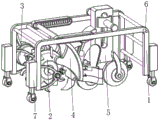
图1为本发明用于城市建设用挖槽开沟机整体结构示意图;Fig. 1 is that the present invention is used for the overall structure schematic diagram of the trenching ditching machine of urban construction;
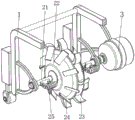
图2为本发明用于城市建设用挖槽开沟机仰视结构示意图;Fig. 2 is a structural schematic diagram of looking up at the trenching and ditching machine used for urban construction according to the present invention;
图3为本发明碎土处理装置截面结构示意图;Fig. 3 is a schematic cross-sectional structure diagram of the broken soil treatment device of the present invention;
图4为本发明碎土处理装置整体结构示意图;Fig. 4 is a schematic diagram of the overall structure of the crushed soil treatment device of the present invention;
图5为本发明拨土装置整体结构示意图;5 is a schematic diagram of the overall structure of the earth moving device of the present invention;
图6为本发明沟槽开设装置截面结构示意图;Fig. 6 is a schematic diagram of the cross-sectional structure of the groove opening device of the present invention;
图7为本发明顶动装置整体结构示意图;7 is a schematic diagram of the overall structure of the jacking device of the present invention;
图8为本发明夯实装置截面结构示意图;Fig. 8 is a schematic cross-sectional structure diagram of a compacting device of the present invention;
图9为本发明受力驱动装置整体结构示意图。Fig. 9 is a schematic diagram of the overall structure of the force driven device of the present invention.
图中:1、机架;2、沟槽开设装置;3、伺服电机;4、碎土处理装置;5、夯实装置;6、把手;7、升降机轮;21、驱动辊;22、配重轮;23、主挖齿;24、斜面挖齿;25、顶动装置;251、顶动连杆;252、顶动头;253、光滑弧面;254、滚珠;41、壳体滑轨;42、碎土挡板;43、复位弹件;44、受力件;45、掘土犁;46、拨土装置;47、推动凸起;461、拨土基板;462、碎土刮条;463、V形弹条;464、推板;465、挡圈;51、限位棒;52、配重夯实块;53、定位板;54、弹性圈;55、受力驱动装置;56、滚压轮;57、球头顶杆;551、柳叶驱动块;552、弯钩导向件;553、连接轮。In the figure: 1. Rack; 2. Groove opening device; 3. Servo motor; 4. Broken soil processing device; 5. Compacting device; 6. Handle; 7. Elevator wheel; 21. Driving roller; 22.
具体实施方式Detailed ways
下面结合附图和具体实施方式对本发明作进一步详细的说明。本发明的实施例是为了示例和描述起见而给出的,而并不是无遗漏的或者将本发明限于所公开的形式。很多修改和变化对于本领域的普通技术人员而言是显而易见的。选择和描述实施例是为了更好说明本发明的原理和实际应用,并且使本领域的普通技术人员能够理解本发明从而设计适于特定用途的带有各种修改的各种实施例。The present invention will be further described in detail below in conjunction with the accompanying drawings and specific embodiments. The embodiments of the present invention have been presented for purposes of illustration and description, but are not intended to be exhaustive or to limit the invention to the form disclosed. Many modifications and changes will be apparent to those of ordinary skill in the art. The embodiment was chosen and described in order to better explain the principles of the invention and the practical application, and to enable others of ordinary skill in the art to understand the invention and design various embodiments with various modifications as are suited to the particular use.
实施例1Example 1
如图1-图5所示,本发明提供一种技术方案:一种用于城市建设用挖槽开沟机,包括机架1,机架1的内表面底部且靠近右端位置设置有沟槽开设装置2,机架1的外表面固定连接有伺服电机3,伺服电机3的输出轴通过联轴器与沟槽开设装置2的外表面端部固定连接,机架1的内表面且靠近沟槽开设装置2的位置设置有碎土处理装置4,机架1的内表面且靠近碎土处理装置4的位置设置有夯实装置5,机架1的外表面顶部固定连接有把手6,机架1的外表面底部安装有升降机轮7;As shown in Figures 1 to 5, the present invention provides a technical solution: a trenching and ditching machine for urban construction, including a
碎土处理装置4包括壳体滑轨41,壳体滑轨41的外表面与机架1的顶部固定连接,壳体滑轨41的内表面滑动连接有碎土挡板42,碎土挡板42的外表面顶部固定连接有复位弹件43,复位弹件43远离碎土挡板42顶部的一端与壳体滑轨41的内表面连接,碎土挡板42的外表面固定连接有受力件44,碎土挡板42的底部固定连接有掘土犁45,碎土挡板42的外表面底部设置有拨土装置46,碎土挡板42的外表面固定连接有推动凸起47。The crushed
碎土挡板42的外表面设置为弧形,受力件44的外表面底部设置有圆弧状,推动凸起47的外表面设置为圆弧面。The outer surface of the
通过升降机轮7将装置移动到指定的位置,此时通过伺服电机3将沟槽开设装置2带动进行转动,对土地进行开挖,随着装置整体的移动,利用掘土犁45向前移动,将开挖后产生的碎土从沟槽中掘出,且碎土挡板42及时将飞溅的碎土进行阻挡,可减少对使用者造成误伤,并利用转动中的沟槽开设装置2与受力件44相互作用,可使得碎土挡板42受到向右侧的推动力,并结合碎土挡板42在壳体滑轨41的导向作用下,使得碎土挡板42带动掘土犁45向右移动,且复位弹件43受到压缩,随着沟槽开设装置2的不停转动,利用顶动力消失,并在复位弹件43的弹力作用下,使得碎土挡板42带动掘土犁45向左侧移动进行复位,如此使得碎土挡板42往复移动,利用掘土犁45往复对碎土进行掘出,可对沟槽内的碎土快速处理,同时拨土装置46还可以将掘出的碎土进一步向外侧推动,以免掉落到沟槽内,并利用推动凸起47直线往复移动,可对夯实装置5施加推动力,边缘后续对沟槽内表面夯实,巧妙的将结构联系在一起。The device is moved to a designated position by the
拨土装置46包括拨土基板461,拨土基板461的外表面边缘与碎土挡板42的外表面转动连接,拨土基板461的底部固定连接有碎土刮条462,拨土基板461的外表面固定连接有V形弹条463,V形弹条463远离拨土基板461的一端与碎土挡板42的外表面固定连接,拨土基板461的外表面顶部固定连接有推板464,推板464的外表面边缘固定连接有挡圈465。The earth-moving
拨土基板461的往外表面设置为弧形,推板464倾斜设置,挡圈465的外表面设置圆弧面。The outer surface of the earth-moving
当装置整体向前移动时,拨土装置46也会随着一起向前移动,此时碎土刮条462的将掘土犁45从沟槽内掘出的碎土进行刮动,并利用碎土刮条462的弧形导向,将刮除后的碎土向远离沟槽的方向推动,使得掘出的碎土不易滚落到沟槽内,无需二次清理,并利用碎土挡板42的直线往复移动,使得碎土刮条462也随着一起往复移动,进而对碎土进行多次刮除,同时利用推板464与夯实装置5之间相互作用,可促进对碎土向外侧推动。When the device as a whole moved forward, the
实施例2Example 2
如图1-图7所示,在实施例1的基础上,沟槽开设装置2包括驱动辊21,驱动辊21的外表面端部通过支架转动连接在机架1的内表面,驱动辊21的外表面端部通过联轴器与伺服电机3的输出轴固定连接,驱动辊21的外表面固定连接有配重轮22,配重轮22的外表面边缘固定连接有主挖齿23,配重轮22的外表面固定连接有斜面挖齿24,驱动辊21的外表面且靠近配重轮22的位置设置有顶动装置25。As shown in Figures 1-7, on the basis of
主挖齿23和斜面挖齿24均匀分布在配重轮22的外表面,顶动装置25设置有两个,且两个顶动装置25对称设置在配重轮22的两侧。The
顶动装置25包括顶动连杆251,顶动连杆251的外表面端部与驱动辊21的外表面固定连接,顶动连杆251远离驱动辊21的一端固定连接有顶动头252,顶动头252的外表面设置为光滑弧面253,光滑弧面253的外表面滚动连接有滚珠254。The jacking
当伺服电机3将驱动辊21带动进行转动时,使得配重轮22和顶动装置25也随着一起转动,此时主挖齿23对土地进行开挖形成沟槽,且斜面挖齿24对沟槽侧面进行开挖,形成锥形沟槽,同时转动中的顶动装置25,在顶动连杆251的支撑下,使得顶动头252的外表面与受力件44外表面接触,并随着持续转动,进而对受力件44施加顶动力,便于碎土挡板42的往复移动,且利用滚珠254的外表面与受力件44的外表面接触时滚动,进而对受力件44采用滚动摩擦,减小了摩擦力,并结合顶动头252的外表面设置为光滑弧面253,使得结构之间运行顺畅,不易出现卡死的情况,并将结构联系在一起。When the
实施例3Example 3
如图1-图9所示,在实施例2的基础上,夯实装置5包括限位棒51,限位棒51的外表面端部与机架1的顶部固定连接,限位棒51的外表面滑动连接有配重夯实块52,限位棒51的外表面且靠近配重夯实块52的位置固定连接有定位板53,限位棒51的外表面底部固定连接有弹性圈54,弹性圈54的底端与配重夯实块52的内部固定连接,配重夯实块52的外表面固定连接有受力驱动装置55,配重夯实块52的外表面底部安装有滚压轮56,配重夯实块52的外表面底部固定连接有球头顶杆57。As shown in Figures 1-9, on the basis of
配重夯实块52的外表面开设有与限位棒51的外表面相适配的滑动孔,球头顶杆57设置有两个,且两个球头顶杆57沿着配重夯实块52对称设置。The outer surface of the
受力驱动装置55包括柳叶驱动块551,柳叶驱动块551倾斜设置,柳叶驱动块551的顶端与配重夯实块52的外表面固定连接,柳叶驱动块551的底端设置有弯钩导向件552,柳叶驱动块551的外表面底部滚动连接有连接轮553。Force driven
当夯实装置5整体被带动向前移动时,并在弹性圈54的弹力作用下,使得配重夯实块52对滚压轮56进行按压,促进滚压轮56的外表面与沟槽内表面贴合,进而对沟槽进行滚压,使得沟槽不易出现塌陷,同时利用推动凸起47向右移动时,会在弯钩导向件552的导向作用下,对柳叶驱动块551施加向上的推动力,使得配重夯实块52带动滚压轮56向上移动,并对弹性圈54进行压缩,随着推动凸起47向左移动,使得推动凸起47与柳叶驱动块551脱离,此时顶压力消失,并在弹性圈54的弹力作用下,使得配重夯实块52带动滚压轮56快速向下移动,进而通过滚压轮56对沟槽内表面进行锤击,进而对沟槽进行夯实,使得沟槽土壤更加紧实,并且利用球头顶杆57随着配重夯实块52向上移动,并结合推板464时倾斜设置,使得球头顶杆57对推板464向外侧推动,进而使得拨土基板461带动碎土刮条462向外侧转动,将碎土拨开,利用结构之间相互联系,相互作用,使得沟槽开设效果好。When the
使用时,通过升降机轮7将装置移动到指定的位置,当伺服电机3将驱动辊21带动进行转动时,使得配重轮22和顶动装置25也随着一起转动,此时主挖齿23对土地进行开挖形成沟槽,且斜面挖齿24对沟槽侧面进行开挖,形成锥形沟槽,同时转动中的顶动装置25,在顶动连杆251的支撑下,使得顶动头252的外表面与受力件44外表面接触,并随着持续转动,进而对受力件44施加顶动力,便于碎土挡板42的往复移动,且随着装置整体的移动,利用掘土犁45向前移动,将开挖后产生的碎土从沟槽中掘出,且碎土挡板42及时将飞溅的碎土进行阻挡,可减少对使用者造成误伤,并利用转动中的沟槽开设装置2与受力件44相互作用,可使得碎土挡板42受到向右侧的推动力,并结合碎土挡板42在壳体滑轨41的导向作用下,使得碎土挡板42带动掘土犁45向右移动,且复位弹件43受到压缩,随着沟槽开设装置2的不停转动,利用顶动力消失,并在复位弹件43的弹力作用下,使得碎土挡板42带动掘土犁45向左侧移动进行复位,如此使得碎土挡板42往复移动,利用掘土犁45往复对碎土进行掘出,可对沟槽内的碎土快速处理,并且当装置整体向前移动时,拨土装置46也会随着一起向前移动,此时碎土刮条462的将掘土犁45从沟槽内掘出的碎土进行刮动,并利用碎土刮条462的弧形导向,将刮除后的碎土向远离沟槽的方向推动,使得掘出的碎土不易滚落到沟槽内,无需二次清理,并利用碎土挡板42的直线往复移动,使得碎土刮条462也随着一起往复移动,进而对碎土进行多次刮除,同时利用推板464与夯实装置5之间相互作用,可促进对碎土向外侧推动,而且当夯实装置5整体被带动向前移动时,并在弹性圈54的弹力作用下,使得配重夯实块52对滚压轮56进行按压,促进滚压轮56的外表面与沟槽内表面贴合,进而对沟槽进行滚压,使得沟槽不易出现塌陷,同时利用推动凸起47向右移动时,会在弯钩导向件552的导向作用下,对柳叶驱动块551施加向上的推动力,使得配重夯实块52带动滚压轮56向上移动,并对弹性圈54进行压缩,随着推动凸起47向左移动,使得推动凸起47与柳叶驱动块551脱离,此时顶压力消失,并在弹性圈54的弹力作用下,使得配重夯实块52带动滚压轮56快速向下移动,进而通过滚压轮56对沟槽内表面进行锤击,进而对沟槽进行夯实,使得沟槽土壤更加紧实,并且利用球头顶杆57随着配重夯实块52向上移动,并结合推板464时倾斜设置,使得球头顶杆57对推板464向外侧推动,进而使得拨土基板461带动碎土刮条462向外侧转动,将碎土拨开,利用结构之间相互联系,相互作用,使得沟槽开设效果好。During use, the device is moved to a designated position by the
显然,所描述的实施例仅仅是本发明的一部分实施例,而不是全部的实施例。基于本发明中的实施例,本领域及相关领域的普通技术人员在没有作出创造性劳动的前提下所获得的所有其他实施例,都应属于本发明保护的范围。本发明中未具体描述和解释说明的结构、装置以及操作方法,如无特别说明和限定,均按照本领域的常规手段进行实施。Apparently, the described embodiments are only some of the embodiments of the present invention, not all of them. Based on the embodiments of the present invention, all other embodiments obtained by those skilled in the art and related fields without creative efforts shall fall within the protection scope of the present invention. The structures, devices and operation methods not specifically described and explained in the present invention, unless otherwise specified and limited, shall be implemented according to conventional means in the art.
Claims (10)
Priority Applications (1)
| Application Number | Priority Date | Filing Date | Title |
|---|---|---|---|
| CN202310236716.0A CN116145754A (en) | 2023-03-13 | 2023-03-13 | Ditching machine for urban construction |
Applications Claiming Priority (1)
| Application Number | Priority Date | Filing Date | Title |
|---|---|---|---|
| CN202310236716.0A CN116145754A (en) | 2023-03-13 | 2023-03-13 | Ditching machine for urban construction |
Publications (1)
| Publication Number | Publication Date |
|---|---|
| CN116145754A true CN116145754A (en) | 2023-05-23 |
Family
ID=86339009
Family Applications (1)
| Application Number | Title | Priority Date | Filing Date |
|---|---|---|---|
| CN202310236716.0A Withdrawn CN116145754A (en) | 2023-03-13 | 2023-03-13 | Ditching machine for urban construction |
Country Status (1)
| Country | Link |
|---|---|
| CN (1) | CN116145754A (en) |
Cited By (1)
| Publication number | Priority date | Publication date | Assignee | Title |
|---|---|---|---|---|
| CN117532747A (en) * | 2023-12-25 | 2024-02-09 | 一鸣建设集团有限公司 | Building wall slotting equipment |
-
2023
- 2023-03-13 CN CN202310236716.0A patent/CN116145754A/en not_active Withdrawn
Cited By (2)
| Publication number | Priority date | Publication date | Assignee | Title |
|---|---|---|---|---|
| CN117532747A (en) * | 2023-12-25 | 2024-02-09 | 一鸣建设集团有限公司 | Building wall slotting equipment |
| CN117532747B (en) * | 2023-12-25 | 2024-04-26 | 一鸣建设集团有限公司 | Building wall slotting equipment |
Similar Documents
| Publication | Publication Date | Title |
|---|---|---|
| CN220704491U (en) | A kind of foundation leveling equipment for construction projects | |
| CN211621542U (en) | Tamping device for earthwork | |
| CN214738362U (en) | Convenient multifunctional cable ditch device of filling soil | |
| CN114000476B (en) | Surface layer tamping device and ditch cleaning tamping method for farmland drainage ditch | |
| CN218479240U (en) | Excavation construction device for reservoir box culvert foundation | |
| CN118292395B (en) | Hydraulic engineering construction method | |
| CN222730641U (en) | Ditching device for side ditch excavator for roadbed drainage engineering | |
| CN114592520A (en) | Building foundation pit construction equipment and building foundation pit construction method | |
| CN208517998U (en) | The ground connection wall brushing device installed on the grooving machine grab | |
| CN211340358U (en) | A kind of crushing equipment for highway pavement | |
| CN111894062B (en) | A trenching equipment for foundation | |
| CN117721862A (en) | A roadbed leveling device for highway construction | |
| CN118835921A (en) | Ice water accumulation block gravelly soil covering layer grouting drilling device | |
| CN118531853A (en) | A backfill soil compacting device based on rock and soil excavation | |
| CN217325309U (en) | Foundation tamping device for civil engineering | |
| CN117145025A (en) | Canal forming machine | |
| CN215669432U (en) | Rammed earth machine with self-cleaning function for construction engineering | |
| CN215290334U (en) | Water conservancy is surveyed with filling hole device | |
| CN215210970U (en) | A rammer for civil engineering | |
| CN116537290A (en) | Excavating mechanism assembly of underground continuous vertical membrane wall building machine | |
| CN214574234U (en) | A foundation pit excavation device for municipal civil construction | |
| CN216973543U (en) | A foundation backfill device for civil construction | |
| CN115748866B (en) | A reservoir box culvert foundation excavation construction equipment | |
| CN115977034A (en) | Slope reinforcement device for farmland drainage canal | |
| CN114908826A (en) | Carry out row's silt mechanism of ditching to ground in water conservancy construction |
Legal Events
| Date | Code | Title | Description |
|---|---|---|---|
| PB01 | Publication | ||
| PB01 | Publication | ||
| SE01 | Entry into force of request for substantive examination | ||
| SE01 | Entry into force of request for substantive examination | ||
| WW01 | Invention patent application withdrawn after publication |
Application publication date: 20230523 |
|
| WW01 | Invention patent application withdrawn after publication |