CN116118139A - Tape casting extruder for tpx release film - Google Patents
Tape casting extruder for tpx release film Download PDFInfo
- Publication number
- CN116118139A CN116118139A CN202310227866.5A CN202310227866A CN116118139A CN 116118139 A CN116118139 A CN 116118139A CN 202310227866 A CN202310227866 A CN 202310227866A CN 116118139 A CN116118139 A CN 116118139A
- Authority
- CN
- China
- Prior art keywords
- controller
- motor
- roller
- release film
- fixedly installed
- Prior art date
- Legal status (The legal status is an assumption and is not a legal conclusion. Google has not performed a legal analysis and makes no representation as to the accuracy of the status listed.)
- Pending
Links
- 238000010345 tape casting Methods 0.000 title description 2
- 230000007246 mechanism Effects 0.000 claims abstract description 52
- 239000000463 material Substances 0.000 claims abstract description 51
- 238000003756 stirring Methods 0.000 claims abstract description 46
- 238000005266 casting Methods 0.000 claims abstract description 24
- 238000001125 extrusion Methods 0.000 claims abstract description 22
- 238000010438 heat treatment Methods 0.000 claims abstract description 21
- 238000002156 mixing Methods 0.000 claims abstract description 15
- 238000005520 cutting process Methods 0.000 claims abstract description 5
- 238000001816 cooling Methods 0.000 claims description 36
- 238000011084 recovery Methods 0.000 claims description 36
- 238000009434 installation Methods 0.000 claims description 19
- 238000009966 trimming Methods 0.000 claims description 11
- 238000010298 pulverizing process Methods 0.000 claims description 4
- 229920006255 plastic film Polymers 0.000 abstract description 36
- 239000002994 raw material Substances 0.000 abstract description 21
- 239000004033 plastic Substances 0.000 abstract description 17
- 238000007373 indentation Methods 0.000 abstract description 6
- 238000004140 cleaning Methods 0.000 abstract description 4
- 239000002991 molded plastic Substances 0.000 abstract 1
- 239000002985 plastic film Substances 0.000 description 35
- 230000009471 action Effects 0.000 description 9
- 238000000034 method Methods 0.000 description 8
- 230000008569 process Effects 0.000 description 7
- 238000004064 recycling Methods 0.000 description 4
- 239000007788 liquid Substances 0.000 description 3
- 238000010586 diagram Methods 0.000 description 2
- 238000005516 engineering process Methods 0.000 description 2
- 239000012634 fragment Substances 0.000 description 2
- 230000005484 gravity Effects 0.000 description 2
- 235000021190 leftovers Nutrition 0.000 description 2
- 230000032258 transport Effects 0.000 description 2
- 239000002699 waste material Substances 0.000 description 2
- 230000009286 beneficial effect Effects 0.000 description 1
- 239000000498 cooling water Substances 0.000 description 1
- 230000000694 effects Effects 0.000 description 1
- 238000005485 electric heating Methods 0.000 description 1
- 239000003822 epoxy resin Substances 0.000 description 1
- 239000003000 extruded plastic Substances 0.000 description 1
- 235000012438 extruded product Nutrition 0.000 description 1
- 239000000945 filler Substances 0.000 description 1
- 235000013611 frozen food Nutrition 0.000 description 1
- 239000012760 heat stabilizer Substances 0.000 description 1
- 238000012423 maintenance Methods 0.000 description 1
- 238000004519 manufacturing process Methods 0.000 description 1
- 239000000155 melt Substances 0.000 description 1
- 238000012986 modification Methods 0.000 description 1
- 230000004048 modification Effects 0.000 description 1
- 239000012768 molten material Substances 0.000 description 1
- 230000003287 optical effect Effects 0.000 description 1
- 238000004806 packaging method and process Methods 0.000 description 1
- 239000004597 plastic additive Substances 0.000 description 1
- 239000004014 plasticizer Substances 0.000 description 1
- 229920000647 polyepoxide Polymers 0.000 description 1
- 239000002861 polymer material Substances 0.000 description 1
Images
Classifications
-
- B—PERFORMING OPERATIONS; TRANSPORTING
- B29—WORKING OF PLASTICS; WORKING OF SUBSTANCES IN A PLASTIC STATE IN GENERAL
- B29C—SHAPING OR JOINING OF PLASTICS; SHAPING OF MATERIAL IN A PLASTIC STATE, NOT OTHERWISE PROVIDED FOR; AFTER-TREATMENT OF THE SHAPED PRODUCTS, e.g. REPAIRING
- B29C48/00—Extrusion moulding, i.e. expressing the moulding material through a die or nozzle which imparts the desired form; Apparatus therefor
- B29C48/03—Extrusion moulding, i.e. expressing the moulding material through a die or nozzle which imparts the desired form; Apparatus therefor characterised by the shape of the extruded material at extrusion
- B29C48/07—Flat, e.g. panels
- B29C48/08—Flat, e.g. panels flexible, e.g. films
-
- B—PERFORMING OPERATIONS; TRANSPORTING
- B26—HAND CUTTING TOOLS; CUTTING; SEVERING
- B26D—CUTTING; DETAILS COMMON TO MACHINES FOR PERFORATING, PUNCHING, CUTTING-OUT, STAMPING-OUT OR SEVERING
- B26D1/00—Cutting through work characterised by the nature or movement of the cutting member or particular materials not otherwise provided for; Apparatus or machines therefor; Cutting members therefor
- B26D1/01—Cutting through work characterised by the nature or movement of the cutting member or particular materials not otherwise provided for; Apparatus or machines therefor; Cutting members therefor involving a cutting member which does not travel with the work
- B26D1/02—Cutting through work characterised by the nature or movement of the cutting member or particular materials not otherwise provided for; Apparatus or machines therefor; Cutting members therefor involving a cutting member which does not travel with the work having a stationary cutting member
- B26D1/03—Cutting through work characterised by the nature or movement of the cutting member or particular materials not otherwise provided for; Apparatus or machines therefor; Cutting members therefor involving a cutting member which does not travel with the work having a stationary cutting member with a plurality of cutting members
- B26D1/035—Cutting through work characterised by the nature or movement of the cutting member or particular materials not otherwise provided for; Apparatus or machines therefor; Cutting members therefor involving a cutting member which does not travel with the work having a stationary cutting member with a plurality of cutting members for thin material, e.g. for sheets, strips or the like
-
- B—PERFORMING OPERATIONS; TRANSPORTING
- B29—WORKING OF PLASTICS; WORKING OF SUBSTANCES IN A PLASTIC STATE IN GENERAL
- B29B—PREPARATION OR PRETREATMENT OF THE MATERIAL TO BE SHAPED; MAKING GRANULES OR PREFORMS; RECOVERY OF PLASTICS OR OTHER CONSTITUENTS OF WASTE MATERIAL CONTAINING PLASTICS
- B29B17/00—Recovery of plastics or other constituents of waste material containing plastics
- B29B17/04—Disintegrating plastics, e.g. by milling
- B29B17/0412—Disintegrating plastics, e.g. by milling to large particles, e.g. beads, granules, flakes, slices
-
- B—PERFORMING OPERATIONS; TRANSPORTING
- B29—WORKING OF PLASTICS; WORKING OF SUBSTANCES IN A PLASTIC STATE IN GENERAL
- B29C—SHAPING OR JOINING OF PLASTICS; SHAPING OF MATERIAL IN A PLASTIC STATE, NOT OTHERWISE PROVIDED FOR; AFTER-TREATMENT OF THE SHAPED PRODUCTS, e.g. REPAIRING
- B29C48/00—Extrusion moulding, i.e. expressing the moulding material through a die or nozzle which imparts the desired form; Apparatus therefor
- B29C48/25—Component parts, details or accessories; Auxiliary operations
- B29C48/27—Cleaning; Purging; Avoiding contamination
- B29C48/271—Cleaning; Purging; Avoiding contamination of feeding units
-
- B—PERFORMING OPERATIONS; TRANSPORTING
- B29—WORKING OF PLASTICS; WORKING OF SUBSTANCES IN A PLASTIC STATE IN GENERAL
- B29C—SHAPING OR JOINING OF PLASTICS; SHAPING OF MATERIAL IN A PLASTIC STATE, NOT OTHERWISE PROVIDED FOR; AFTER-TREATMENT OF THE SHAPED PRODUCTS, e.g. REPAIRING
- B29C48/00—Extrusion moulding, i.e. expressing the moulding material through a die or nozzle which imparts the desired form; Apparatus therefor
- B29C48/25—Component parts, details or accessories; Auxiliary operations
- B29C48/285—Feeding the extrusion material to the extruder
-
- B—PERFORMING OPERATIONS; TRANSPORTING
- B29—WORKING OF PLASTICS; WORKING OF SUBSTANCES IN A PLASTIC STATE IN GENERAL
- B29C—SHAPING OR JOINING OF PLASTICS; SHAPING OF MATERIAL IN A PLASTIC STATE, NOT OTHERWISE PROVIDED FOR; AFTER-TREATMENT OF THE SHAPED PRODUCTS, e.g. REPAIRING
- B29C48/00—Extrusion moulding, i.e. expressing the moulding material through a die or nozzle which imparts the desired form; Apparatus therefor
- B29C48/25—Component parts, details or accessories; Auxiliary operations
- B29C48/355—Conveyors for extruded articles
-
- B—PERFORMING OPERATIONS; TRANSPORTING
- B29—WORKING OF PLASTICS; WORKING OF SUBSTANCES IN A PLASTIC STATE IN GENERAL
- B29C—SHAPING OR JOINING OF PLASTICS; SHAPING OF MATERIAL IN A PLASTIC STATE, NOT OTHERWISE PROVIDED FOR; AFTER-TREATMENT OF THE SHAPED PRODUCTS, e.g. REPAIRING
- B29C48/00—Extrusion moulding, i.e. expressing the moulding material through a die or nozzle which imparts the desired form; Apparatus therefor
- B29C48/25—Component parts, details or accessories; Auxiliary operations
- B29C48/36—Means for plasticising or homogenising the moulding material or forcing it through the nozzle or die
- B29C48/395—Means for plasticising or homogenising the moulding material or forcing it through the nozzle or die using screws surrounded by a cooperating barrel, e.g. single screw extruders
- B29C48/40—Means for plasticising or homogenising the moulding material or forcing it through the nozzle or die using screws surrounded by a cooperating barrel, e.g. single screw extruders using two or more parallel screws or at least two parallel non-intermeshing screws, e.g. twin screw extruders
- B29C48/405—Intermeshing co-rotating screws
-
- B—PERFORMING OPERATIONS; TRANSPORTING
- B29—WORKING OF PLASTICS; WORKING OF SUBSTANCES IN A PLASTIC STATE IN GENERAL
- B29C—SHAPING OR JOINING OF PLASTICS; SHAPING OF MATERIAL IN A PLASTIC STATE, NOT OTHERWISE PROVIDED FOR; AFTER-TREATMENT OF THE SHAPED PRODUCTS, e.g. REPAIRING
- B29C48/00—Extrusion moulding, i.e. expressing the moulding material through a die or nozzle which imparts the desired form; Apparatus therefor
- B29C48/25—Component parts, details or accessories; Auxiliary operations
- B29C48/88—Thermal treatment of the stream of extruded material, e.g. cooling
- B29C48/885—External treatment, e.g. by using air rings for cooling tubular films
-
- B—PERFORMING OPERATIONS; TRANSPORTING
- B29—WORKING OF PLASTICS; WORKING OF SUBSTANCES IN A PLASTIC STATE IN GENERAL
- B29C—SHAPING OR JOINING OF PLASTICS; SHAPING OF MATERIAL IN A PLASTIC STATE, NOT OTHERWISE PROVIDED FOR; AFTER-TREATMENT OF THE SHAPED PRODUCTS, e.g. REPAIRING
- B29C48/00—Extrusion moulding, i.e. expressing the moulding material through a die or nozzle which imparts the desired form; Apparatus therefor
- B29C48/25—Component parts, details or accessories; Auxiliary operations
- B29C48/88—Thermal treatment of the stream of extruded material, e.g. cooling
- B29C48/911—Cooling
- B29C48/9135—Cooling of flat articles, e.g. using specially adapted supporting means
-
- B—PERFORMING OPERATIONS; TRANSPORTING
- B29—WORKING OF PLASTICS; WORKING OF SUBSTANCES IN A PLASTIC STATE IN GENERAL
- B29B—PREPARATION OR PRETREATMENT OF THE MATERIAL TO BE SHAPED; MAKING GRANULES OR PREFORMS; RECOVERY OF PLASTICS OR OTHER CONSTITUENTS OF WASTE MATERIAL CONTAINING PLASTICS
- B29B17/00—Recovery of plastics or other constituents of waste material containing plastics
- B29B17/04—Disintegrating plastics, e.g. by milling
- B29B2017/0424—Specific disintegrating techniques; devices therefor
- B29B2017/0476—Cutting or tearing members, e.g. spiked or toothed cylinders or intermeshing rollers
-
- Y—GENERAL TAGGING OF NEW TECHNOLOGICAL DEVELOPMENTS; GENERAL TAGGING OF CROSS-SECTIONAL TECHNOLOGIES SPANNING OVER SEVERAL SECTIONS OF THE IPC; TECHNICAL SUBJECTS COVERED BY FORMER USPC CROSS-REFERENCE ART COLLECTIONS [XRACs] AND DIGESTS
- Y02—TECHNOLOGIES OR APPLICATIONS FOR MITIGATION OR ADAPTATION AGAINST CLIMATE CHANGE
- Y02P—CLIMATE CHANGE MITIGATION TECHNOLOGIES IN THE PRODUCTION OR PROCESSING OF GOODS
- Y02P70/00—Climate change mitigation technologies in the production process for final industrial or consumer products
- Y02P70/10—Greenhouse gas [GHG] capture, material saving, heat recovery or other energy efficient measures, e.g. motor control, characterised by manufacturing processes, e.g. for rolling metal or metal working
Landscapes
- Engineering & Computer Science (AREA)
- Mechanical Engineering (AREA)
- Physics & Mathematics (AREA)
- Thermal Sciences (AREA)
- Environmental & Geological Engineering (AREA)
- Life Sciences & Earth Sciences (AREA)
- Forests & Forestry (AREA)
- Extrusion Moulding Of Plastics Or The Like (AREA)
Abstract
本发明涉及流延机技术领域,本发明公开了一种用于tpx离型膜的流延挤出机,包括:基座、搅拌箱、加热箱、模头和控制器,所述搅拌箱设置于基座的顶部,所述加热箱设置于所述搅拌箱的左端,所述模头设置于加热箱的左端,所述控制器固定安装于搅拌箱的前侧,挤出机构设置于所述搅拌箱的右端。该用于tpx离型膜的流延挤出机,可以稳定的输送塑料原料,避免上料速度不稳定或发生卡料,保证成品的质量,并且具有自清洁特性,避免挂壁现象,可以自动将成型的塑料薄膜牵引而出,无需人工操作,维护简单,省时省力,还采用限压痕后切割的技术方案,可以自动对余料进行切除,将余料进行收集并粉碎,便于再次利用,无需人工进行收集。

The invention relates to the technical field of casting machines. The invention discloses a casting extruder for tpx release film, comprising: a base, a stirring box, a heating box, a die head and a controller. The stirring box is set On the top of the base, the heating box is set on the left end of the stirring box, the die head is set on the left end of the heating box, the controller is fixedly installed on the front side of the stirring box, and the extrusion mechanism is set on the Right end of the mixing box. The casting extruder used for tpx release film can stably transport plastic raw materials, avoid unstable feeding speed or material jams, ensure the quality of finished products, and have self-cleaning characteristics, avoid wall hanging phenomenon, and can automatically The molded plastic film is pulled out without manual operation, easy to maintain, time-saving and labor-saving, and adopts the technical solution of cutting after indentation, which can automatically cut off the remaining material, collect and crush the remaining material, so that it can be reused , without manual collection.
Description
技术领域technical field
本发明涉及流延机技术领域,具体为一种用于tpx离型膜的流延挤出机。The invention relates to the technical field of casting machines, in particular to a casting extruder for TPX release films.
背景技术Background technique
流延是一种塑料膜生产工艺,先经过挤出机把原料塑化熔融,通过T型结构成型模具挤出,呈片状流延至平稳旋转的冷却辊筒的辊面上,膜片在冷却辊筒上经冷却降温定型,再经牵引、切边后把制品收卷,Tpx离型膜的挤出制品如薄膜、涂布纸、管、圆棒等,在冷冻食品包装、离型纸、烘烤瓦楞纸、环氧树脂硬化用离型纸等方面均有应用;Casting is a plastic film production process. First, the raw materials are plasticized and melted by an extruder, extruded through a T-shaped structure forming die, and cast in sheet form to the roll surface of a cooling roller that rotates smoothly. The film is cooled After being cooled and shaped on the roller, the product is rolled up after traction and trimming. The extruded products of Tpx release film, such as film, coated paper, tube, round rod, etc., are used in frozen food packaging, release paper, It is used in baking corrugated paper, release paper for epoxy resin hardening, etc.;
流延挤出机的主要工作原理,将高分子聚合物物料干燥后,与需要的添加填充料、增塑剂、热稳定剂及其他塑料助剂等按配比计重后混合、吸入料斗,进入料筒螺杆,料筒内的螺杆转动,将物料向前输送,由于采用料筒外电加热,物料温度上升和利用料筒内的螺杆转动,使物料塑化熔融后均匀从模具口挤出,成型薄片状熔料流延至平稳转动的辊筒上,再经多级牵引和切边,最终卷取成薄膜产品;The main working principle of the tape casting extruder is to dry the polymer material, mix it with the required fillers, plasticizers, heat stabilizers and other plastic additives according to the proportion, then suck it into the hopper, and enter Barrel screw, the screw in the barrel rotates to convey the material forward. Due to the use of electric heating outside the barrel, the temperature of the material rises and the screw in the barrel rotates, so that the material is plasticized and melted and extruded from the mold mouth evenly. The flake-like molten material is cast onto a smoothly rotating roller, and then after multi-stage traction and edge trimming, it is finally wound into a film product;
在现有技术中,在制品收卷前需要进行切边,切下的余料需要进行处理后,在此进行加工,但是现有的流延挤出机采用切刀对余料进行切除,在对塑料薄膜进行牵引的牵引力不恒定,导致切下的余料宽度不恒定,且无法自动对余料进行回收再利用,需要人工收集后处理,费时费力,并且现有的流延挤出机大多是人工或使用上料机,将原料倾倒入上料斗中,原料在自身重量作用下进入挤出机,该过程的上料速度不稳定,集料斗发生卡料时,将导致在挤出过程中可能存在气泡,影响成品质量,此外,无法自动对成型的塑料薄膜进行牵引,每次使用前均需要人工进行牵引。In the prior art, trimming is required before the product is rolled, and the remaining material needs to be processed before being processed here. However, the existing casting extruder uses a cutter to cut off the remaining material. The traction force of pulling the plastic film is not constant, resulting in the inconstant width of the cut off material, and the remaining material cannot be recycled and reused automatically, it needs to be manually collected and processed, which is time-consuming and laborious, and most of the existing casting extruders It is manually or using a feeding machine to pour the raw materials into the feeding hopper. The raw materials enter the extruder under the action of their own weight. The feeding speed of this process is unstable. When the collecting hopper jams, it will lead to There may be air bubbles, which will affect the quality of the finished product. In addition, the formed plastic film cannot be pulled automatically, and it needs to be pulled manually before each use.
发明内容Contents of the invention
本发明的目的在于提供一种用于tpx离型膜的流延挤出机,以至少解决现有技术无法自动对成型的塑料薄膜进行牵引、自动切除余料困难、无法余料回收、上料不连续而影响产成品质量的问题。The purpose of the present invention is to provide a casting extruder for tpx release film, to at least solve the problem that the existing technology cannot automatically pull the formed plastic film, the difficulty of automatically removing the remaining material, and the inability to recycle the remaining material and feed the material Problems that are discontinuous and affect the quality of finished products.
为实现上述目的,本发明提供如下技术方案:一种用于tpx离型膜的流延挤出机,包括:基座、搅拌箱、加热箱、模头和控制器,所述搅拌箱设置于基座的顶部,所述加热箱设置于所述搅拌箱的左端,所述模头设置于加热箱的左端,所述控制器固定安装于搅拌箱的前侧,且所述加热箱与控制器电性连接,还包括:挤出机构,挤出机构设置于所述搅拌箱的右端,所述挤出机构通过控制器操控;上料机构设置于所述搅拌箱的顶部,所述上料机构通过控制器操控;延流机构设置于所述基座的左侧,所述延流机构通过控制器操控;余料回收机构设置于所述延流机构的前侧,所述余料回收机构通过控制器操控;To achieve the above object, the present invention provides the following technical solutions: a casting extruder for tpx release film, comprising: a base, a stirring box, a heating box, a die and a controller, the stirring box is arranged on The top of the base, the heating box is arranged at the left end of the stirring box, the die head is arranged at the left end of the heating box, the controller is fixedly installed on the front side of the stirring box, and the heating box and the controller The electrical connection also includes: an extrusion mechanism, which is arranged on the right end of the mixing box, and the extrusion mechanism is controlled by a controller; a feeding mechanism is arranged on the top of the mixing box, and the feeding mechanism It is controlled by the controller; the flow extension mechanism is arranged on the left side of the base, and the flow extension mechanism is controlled by the controller; the surplus material recovery mechanism is arranged on the front side of the flow extension mechanism, and the surplus material recovery mechanism passes through controller manipulation;
目的在于将物料融化挤出,所述挤出机构包括:挤压电机,挤压电机固定安装于所述基座的顶部右端,且与所述控制器电性连接;第一齿轮固定安装于所述挤压电机的输出端;共轭螺杆数量为两个,分别可旋转的安装于所述搅拌箱的内腔右端前后两侧,且两个所述共轭螺杆共轭啮合;第二齿轮数量为两个,分别固定安装于两个所述共轭螺杆的右端,且两个所述第二齿轮均与第一齿轮啮合。The purpose is to melt and extrude the material. The extrusion mechanism includes: an extrusion motor, which is fixedly installed on the top right end of the base and is electrically connected to the controller; the first gear is fixedly installed on the The output end of the above-mentioned extrusion motor; the number of conjugate screws is two, which are respectively rotatably installed on the front and rear sides of the right end of the inner cavity of the mixing box, and the two conjugate screws are engaged in conjugate engagement; the number of the second gear There are two, fixedly mounted on the right ends of the two conjugate screws respectively, and the two second gears are both meshed with the first gear.
目的在于避免物料的挂壁现象,优选的,所述共轭螺杆的叶片螺距约为旋转轴直径的一半,且两个所述共轭螺杆之间的叶片之间相互啮合。The purpose is to avoid material hanging on the wall. Preferably, the pitch of the blades of the conjugated screw is about half of the diameter of the rotating shaft, and the blades between the two conjugated screws mesh with each other.
优选的,所述上料机构包括:进料口,进料口开设于所述搅拌箱的顶部;上料斗固定安装于所述进料口的顶部;送料组件设置于所述基座的后侧,且与所述控制器电性连接。Preferably, the feeding mechanism includes: a feeding port, which is opened on the top of the stirring box; a hopper is fixedly installed on the top of the feeding port; a feeding assembly is arranged on the rear side of the base , and is electrically connected with the controller.
目的在于持续地进行送料,优选的,所述送料组件包括:支架,支架设置于所述基座的后侧;搅拌电机固定安装于所述支架的顶部,且与所述控制器电性连接;转轴固定安装于所述搅拌电机的输出端;搅拌杆数量为若干个,分别沿周向地设置于所述转轴的侧壁;螺旋输送杆设置于所述转轴的底部,且与所述进料口相适配插接。The purpose is to continuously feed materials. Preferably, the feeding assembly includes: a bracket, which is arranged on the rear side of the base; a stirring motor is fixedly installed on the top of the bracket and is electrically connected to the controller; The rotating shaft is fixedly installed on the output end of the stirring motor; the number of stirring rods is several, which are respectively arranged on the side wall of the rotating shaft along the circumference; the screw conveying rod is arranged at the bottom of the rotating shaft, and is connected with the feeding The mouth is suitable for plugging.
目的在于将原料持续的输送进入搅拌箱的内腔,优选的,所述延流机构包括:安装架,安装架设置于所述基座的左侧;冷却辊可旋转地安装于所述安装架的内腔前后两侧右端,且所述冷却辊位于模头的下方;第一电机设置于所述安装架的后侧,所述冷却辊与第一电机的输出端固定连接,且所述第一电机与控制器电性连接;剥离辊可旋转地安装于所述安装架的内腔前后两侧中间位置,且与所述冷却辊紧密接触;牵引辊数量为两个,均可旋转地安装于所述安装架的内腔前后两侧左端,且两个所述牵引辊的侧壁紧密接触;第二电机,设置于所述安装架的后侧,位于上方的所述牵引辊与第二电机的输出端固定连接,且所述第一电机与控制器电性连接;导向板,设置于所述安装架的内腔前后两侧,且所述导向板从右至左逐渐向下倾斜;剥离刮片,固定安装于所述安装座的顶部,且所述剥离刮片与冷却辊的左上角紧密接触。The purpose is to continuously convey the raw materials into the inner cavity of the mixing box. Preferably, the flow extension mechanism includes: a mounting frame, which is arranged on the left side of the base; a cooling roller is rotatably mounted on the mounting frame The right end of the front and rear sides of the inner cavity, and the cooling roller is located below the die head; the first motor is arranged on the rear side of the mounting frame, the cooling roller is fixedly connected to the output end of the first motor, and the first A motor is electrically connected to the controller; the peeling roller is rotatably installed in the middle of the front and rear sides of the inner cavity of the mounting frame, and is in close contact with the cooling roller; the number of traction rollers is two, and they can be rotatably installed At the left end of the front and rear sides of the inner cavity of the installation frame, and the side walls of the two traction rollers are in close contact; the second motor is arranged on the rear side of the installation frame, and the traction roller at the top is in contact with the second motor. The output end of the motor is fixedly connected, and the first motor is electrically connected to the controller; the guide plate is arranged on the front and rear sides of the inner cavity of the mounting frame, and the guide plate is gradually inclined downward from right to left; The peeling scraper is fixedly installed on the top of the installation seat, and the peeling scraper is in close contact with the upper left corner of the cooling roller.
目的在于将tpx离型膜的多余边料进行切除,优选的,所述余料回收机构包括:安装杆,安装杆设置于所述安装架的顶部;升降组件,设置于安装架的顶部左侧,且与所述控制器电性连接;回料斗设置于所述安装架内腔前侧,且所述回料斗的前侧呈敞开设置;回收组件设置于所述回料斗的后侧,且与所述控制器电性连接,切边组件,设置于所述升降组件的底部。The purpose is to cut off the excess edge material of the tpx release film. Preferably, the residual material recovery mechanism includes: a mounting rod, which is arranged on the top of the mounting frame; a lifting assembly, which is arranged on the left side of the top of the mounting frame , and is electrically connected with the controller; the return hopper is arranged on the front side of the inner cavity of the installation frame, and the front side of the return hopper is open; the recovery component is arranged on the back side of the return hopper, and is connected with the The controller is electrically connected to the trimming component, which is arranged at the bottom of the lifting component.
优选的,所述升降组件包括:安装座,固定安装于所述安装架的顶部左侧;电控滑台,设置于安装座的右侧,且与所述控制器电性连接;升降座,固定安装于所述电控滑台的输出端;安装板,设置于所述升降座的底部;滑杆,数量为两个,分别可滑动地安装于所述安装板的前后两端;限位块,数量为两个,分别设置于两个所述滑杆的顶部;滑动架,固定安装于两个所述滑杆的底部;弹簧,数量为两个,分别套接于两个所述滑杆的外壁,且一端分别卡接于安装板的底部,另一端分别卡接于滑动架的顶部。Preferably, the lifting assembly includes: a mounting base, fixedly installed on the left side of the top of the mounting frame; an electric control slide, arranged on the right side of the mounting base, and electrically connected to the controller; a lifting base, Fixedly installed on the output end of the electric control slide; the installation plate is arranged on the bottom of the lifting seat; the number of slide bars is two, which are slidably installed on the front and rear ends of the installation plate respectively; Blocks, two in number, respectively arranged on the tops of the two slide bars; slide frames, fixedly installed on the bottoms of the two slide bars; springs, two in number, respectively sleeved on the two slide bars the outer wall of the rod, and one end is respectively clamped to the bottom of the mounting plate, and the other end is respectively clamped to the top of the sliding frame.
目的在于将余料进行回收处理,优选的,所述回收组件包括:回收辊,回收辊数量为两个,均可旋转地安装于回料斗的内腔左右侧壁顶端,且两个所述回收辊的侧壁紧密接触;第三电机固定安装于所述回料斗的右侧,位于前侧的所述回收辊与第三电机的输出端固定连接,且所述第三电机与控制器电性连接;第三齿轮可旋转地安装于所述回料斗的左侧,且所述第三齿轮与位于前侧的回收辊固定连接;第四齿轮可旋转地安装于所述回料斗的左侧,且与所述第三齿轮相适配啮合;粉碎辊数量为两个,分别可旋转地安装于所述回料斗的内腔左右侧壁底端;第五齿轮数量为两个,分别固定安装于两个所述粉碎辊的左端,两个所述第五齿轮相互啮合,且位于前侧的所述第五齿轮与第四齿轮啮合;导向槽,设置于所述安装架的内腔后侧,且所述导向槽从后侧至前侧逐渐向下倾斜。The purpose is to recycle the remaining materials. Preferably, the recovery assembly includes: two recovery rollers, which are rotatably installed on the top of the left and right side walls of the inner cavity of the return hopper, and the two recovery rollers The side walls of the rollers are in close contact; the third motor is fixedly installed on the right side of the return hopper, the recovery roller on the front side is fixedly connected to the output end of the third motor, and the third motor is electrically connected to the controller connection; the third gear is rotatably installed on the left side of the return hopper, and the third gear is fixedly connected with the recovery roller located on the front side; the fourth gear is rotatably installed on the left side of the return hopper, And it is matched and meshed with the third gear; there are two crushing rollers, which are respectively rotatably installed at the bottom of the left and right side walls of the inner cavity of the return hopper; there are two fifth gears, which are respectively fixedly installed on At the left ends of the two crushing rollers, the two fifth gears mesh with each other, and the fifth gear on the front side meshes with the fourth gear; the guide groove is arranged on the rear side of the inner cavity of the mounting frame, And the guide groove is gradually inclined downward from the rear side to the front side.
目的在于对余料进行切除,优选的,所述切边组件包括:从动辊,可旋转地安装于所述滑动架的内腔前后两侧;压痕刀,数量为两个,分别设置于从动辊的外壁前后两端;切刀,数量为两个,分别设置于滑动架的左侧前后两端;限位杆,数量为两个,分别社会自愈升降座的左侧前后两端;第一连杆,数量为两个,分别可旋转地安装于两个限位杆的左侧;第二连杆,数量为两个,一端分别可旋转地安装于两个所述第一连杆的底端,且另一端分别可旋转地安装于两个所述切刀的顶部;挡板,数量为两个,分别设置于两个所述第一连杆的左侧;刀片,数量为两个,分别设置于两个挡板的底端。The purpose is to cut off the remaining material. Preferably, the trimming assembly includes: a driven roller, which is rotatably installed on the front and rear sides of the inner cavity of the sliding frame; two creasing knives, which are respectively arranged on The front and rear ends of the outer wall of the driven roller; the number of cutters is two, which are respectively set at the left and front ends of the sliding frame; the number of limit rods is two, and the number is two, respectively, at the left and front ends of the social self-healing lifting seat There are two first connecting rods, which are respectively rotatably installed on the left sides of the two limit rods; the second connecting rods are two in number, and one end is respectively rotatably installed on the two first connecting rods; The bottom end of the rod, and the other end is rotatably mounted on the tops of the two cutters; the baffle plate is two in number, and is respectively arranged on the left side of the two first connecting rods; the blades are in the number of two, respectively arranged at the bottom ends of the two baffles.
目的在于将余料进行粉碎,以便于再次利用,优选的,所述粉碎辊从前至后等距的设置有若干个齿刀,相邻齿刀的间距与齿刀宽度相等,相邻的两个所述粉碎辊安装方向相反且相互插接。The purpose is to crush the remaining materials so as to be reused. Preferably, the crushing roller is equidistantly provided with several toothed knives from front to back, and the distance between adjacent toothed knives is equal to the width of the toothed knife. The crushing rollers are installed in opposite directions and inserted into each other.
本发明与现有技术相比的有益效果在于:The beneficial effect of the present invention compared with prior art is:
1、本发明通过控制器控制搅拌电机的输出端带动转轴旋转,搅拌杆对上料斗的内腔中的塑料原料进行搅拌,并对上料斗的内壁进行清理,随着螺旋输送杆的旋转,螺旋输送杆的螺旋叶片将粉状原料向搅拌箱的内腔中推移进行输送,因此,可以稳定的输送塑料原料,避免上料速度不稳定或发生卡料,保证成品的质量。1. In the present invention, the output end of the stirring motor is controlled by the controller to drive the rotating shaft to rotate. The stirring rod stirs the plastic raw materials in the inner cavity of the upper hopper, and cleans the inner wall of the upper hopper. With the rotation of the screw conveying rod, the screw The helical blade of the conveying rod pushes the powdery raw material into the inner cavity of the mixing box for conveying. Therefore, the plastic raw material can be conveyed stably, avoiding unstable feeding speed or material jam, and ensuring the quality of the finished product.
2、本发明通过控制器控制挤压电机的输出端带动第一齿轮旋转,在第一齿轮与两个第二齿轮的啮合作用下带动两个共轭螺杆同方向转动,原料在自身重量和与搅拌箱、加热箱内壁之间的摩擦作用下,使共轭螺杆的螺旋叶片将原料向左侧推移进行输送,由于两个共轭螺杆之间共轭啮合,即当其中一个共轭螺杆的螺旋凹槽中的废料会被另一个共轭螺杆的螺旋叶片挤出,因此,具有自清洁特性,避免挂壁现象,维护简单,省时省力。2. In the present invention, the output end of the extrusion motor is controlled by the controller to drive the first gear to rotate, and the two conjugate screws are driven to rotate in the same direction under the meshing action of the first gear and the two second gears. Under the action of friction between the inner walls of the stirring box and the heating box, the helical blades of the conjugated screw push the raw material to the left for conveying. Due to the conjugate engagement between the two conjugated screws, that is, when the spiral of one of the conjugated screws The waste in the groove will be extruded by the helical blade of another conjugate screw, so it has self-cleaning characteristics, avoids wall hanging phenomenon, simple maintenance, and saves time and effort.
3、本发明通过融化的塑料原料从模头滴落在冷却辊的顶部,控制器控制第一电机的输出端带动冷却辊旋转,随着冷却辊的旋转,塑料液体在冷却辊的表面流延形成塑料薄膜,成型的塑料薄膜旋转至剥离刮片位置后,被剥离刮片剥离,在塑料薄膜自身重力作用下,被剥离的塑料薄膜绕过剥离辊,在导向板的导向作用下进入两个牵引辊之间,控制器控制第二电机的输出端带动牵引辊旋转,在两个牵引辊同时向内侧旋转,将塑料薄膜从左侧牵引而出,因此,可以自动将成型的塑料薄膜牵引而出,无需人工操作。3. In the present invention, the melted plastic raw material drips from the die on the top of the cooling roller, and the controller controls the output end of the first motor to drive the cooling roller to rotate. With the rotation of the cooling roller, the plastic liquid is cast on the surface of the cooling roller The plastic film is formed, and the formed plastic film rotates to the position of the peeling blade, and is peeled off by the peeling blade. Under the action of the plastic film's own gravity, the peeled plastic film bypasses the peeling roller and enters two Between the traction rollers, the controller controls the output end of the second motor to drive the traction rollers to rotate. When the two traction rollers rotate inward at the same time, the plastic film is pulled out from the left side. Therefore, the formed plastic film can be automatically pulled out. out without manual operation.
4、本发明通过牵引辊牵引塑料薄膜过程中,控制器控制电控滑台的输出端驱动升降座向下移动,直至滑动架与安装架接触,从动辊与剥离辊紧密接触,压痕刀对塑料薄膜的前后两侧进行压痕,随着牵引辊牵引塑料薄膜,两个切刀将塑料薄膜两侧的余料进行切割,控制器控制电控滑台的输出端驱动升降座继续向下移动,在此过程中安装板和滑动架之间的弹簧受力压缩,安装板与滑动架之间的距离缩短,在两个第二连杆的连接作用下,两个第一连杆带动两个挡板向下旋转,两个挡板底部的刀片对塑料薄膜前后两侧的余料进行切断,因此,采用限压痕后切割的技术方案,可以自动对余料进行切除。4. In the process of pulling the plastic film through the pulling roller, the controller controls the output end of the electronically controlled sliding table to drive the lifting seat to move downward until the sliding frame contacts the mounting frame, the driven roller and the peeling roller are in close contact, and the indentation knife Make indentations on the front and rear sides of the plastic film, and as the traction roller pulls the plastic film, the two cutters cut the remaining material on both sides of the plastic film, and the controller controls the output end of the electric control slide to drive the lifting seat to continue downward During this process, the spring between the mounting plate and the sliding frame is compressed, and the distance between the mounting plate and the sliding frame is shortened. Under the connection of the two second connecting rods, the two first connecting rods drive the two The first baffle rotates downward, and the blades at the bottom of the two baffles cut off the remaining material on the front and rear sides of the plastic film. Therefore, the technical solution of cutting after limiting the indentation can automatically cut off the remaining material.
5、本发明通过控制器控制第三电机的输出端带动两个回收辊同时向内侧旋转,在第三齿轮、第四齿轮和第五齿轮的啮合下,两个粉碎辊同时向内侧旋转,被切割下的余料在两个回收辊的牵引下进入回料斗,随后被向内侧旋转的粉碎辊粉碎成塑料碎片,因此,还可以将余料进行收集并粉碎,便于再次利用,无需人工进行收集。5. In the present invention, the output end of the third motor is controlled by the controller to drive the two recovery rollers to rotate inward at the same time. Under the meshing of the third gear, the fourth gear and the fifth gear, the two crushing rollers rotate inward at the same time, and are The cut leftovers enter the return hopper under the traction of two recovery rollers, and then are crushed into plastic fragments by the inwardly rotating crushing rollers. Therefore, the leftovers can also be collected and crushed for reuse without manual collection .
附图说明Description of drawings
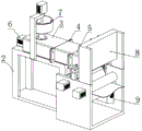
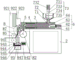
图1为本发明结构示意图。Fig. 1 is a schematic diagram of the structure of the present invention.
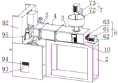
图2为本发明结构示意图。Fig. 2 is a schematic diagram of the structure of the present invention.
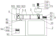
图3为本发明主视图。Fig. 3 is a front view of the present invention.
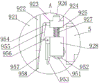
图4为A处放大图。Figure 4 is an enlarged view of A.
图5为本发明主视剖面图。Fig. 5 is a front sectional view of the present invention.
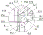
图6为B处放大图。Figure 6 is an enlarged view of B.
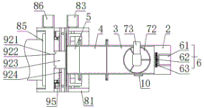
图7为本发明俯视图。Fig. 7 is a top view of the present invention.
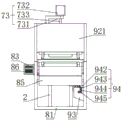
图8为本发明左视图。Fig. 8 is a left view of the present invention.
图9为回收组件左视剖面图。Fig. 9 is a left sectional view of the recovery assembly.
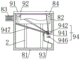
图中:2、基座;3、搅拌箱;4、加热箱;5、模头;6、挤出机构;61、挤压电机;62、第一齿轮;63、第二齿轮;64、共轭螺杆;7、上料机构;71、进料口;72、上料斗;73、送料组件;731、支架;732、搅拌电机;733、转轴;734、搅拌杆;735、螺旋输送杆;8、延流机构;81、安装架;82、冷却辊;83、第一电机;84、剥离辊;85、牵引辊;86、第二电机;87、导向板;88、剥离刮片;9、余料回收机构;91、安装杆;92、升降组件;921、安装座;922、电控滑台;923、升降座;924、安装板;925、滑杆;926、限位块;927、弹簧;928、滑动架;93、回料斗;94、回收组件;941、回收辊;942、第三电机;943、第三齿轮;944、第四齿轮;945、第五齿轮;946、粉碎辊;947、导向槽;95、切边组件;951、从动辊;952、压痕刀;953、切刀;954、限位杆;955、第一连杆;956、第二连杆;957、挡板;958、刀片;10、控制器。In the figure: 2, base; 3, stirring box; 4, heating box; 5, die head; 6, extrusion mechanism; 61, extrusion motor; 62, first gear; 63, second gear; 64, total Yoke screw; 7, feeding mechanism; 71, feeding port; 72, hopper; 73, feeding assembly; 731, bracket; 732, stirring motor; 733, rotating shaft; 734, stirring rod; 735, screw conveying rod; 8 , flow extension mechanism; 81, mounting frame; 82, cooling roller; 83, first motor; 84, peeling roller; 85, traction roller; 86, second motor; 87, guide plate; 88, peeling blade; 9, Surplus material recovery mechanism; 91, installation rod; 92, lifting assembly; 921, mounting seat; 922, electric control slide table; 923, lifting seat; 924, mounting plate; 925, sliding rod; Spring; 928, sliding frame; 93, return hopper; 94, recovery assembly; 941, recovery roller; 942, third motor; 943, third gear; 944, fourth gear; 945, fifth gear; 946, crushing roller ; 947, guide groove; 95, trimming assembly; 951, driven roller; 952, indentation knife; , baffle; 958, blade; 10, controller.
具体实施方式Detailed ways
下面将结合本发明实施例中的附图,对本发明实施例中的技术方案进行清楚、完整地描述,显然,所描述的实施例仅仅是本发明一部分实施例,而不是全部的实施例。基于本发明中的实施例,本领域普通技术人员在没有做出创造性劳动前提下所获得的所有其他实施例,都属于本发明保护的范围。The following will clearly and completely describe the technical solutions in the embodiments of the present invention with reference to the accompanying drawings in the embodiments of the present invention. Obviously, the described embodiments are only some, not all, embodiments of the present invention. Based on the embodiments of the present invention, all other embodiments obtained by persons of ordinary skill in the art without making creative efforts belong to the protection scope of the present invention.
请参阅图1-9,本发明提供一种用于tpx离型膜的流延挤出机技术方案,包括:基座2、搅拌箱3、加热箱4、模头5、挤出机构6、上料机构7、延流机构8、余料回收机构9和控制器10,搅拌箱3设置于基座2的顶部,加热箱4设置于搅拌箱3的左端,模头5设置于加热箱4的左端,控制器10固定安装于搅拌箱3的前侧,且加热箱4与控制器10电性连接,挤出机构6设置于搅拌箱3的右端,挤出机构6通过控制器10操控,上料机构7设置于搅拌箱3的顶部,上料机构7通过控制器10操控,延流机构8设置于基座2的左侧,延流机构8通过控制器10操控,余料回收机构9设置于延流机构8的前侧,余料回收机构9通过控制器10操控;Please refer to Figures 1-9, the present invention provides a technical solution for casting extruder for tpx release film, including:
通过上料机构7将原料稳定的输送进入搅拌箱3的内腔,挤出机构6将原料从右至左地输送,塑料在加热箱4中融化,并通过模头5挤出,延流机构8将挤出的塑料流延成塑料膜,余料回收机构9将多余边料切割并进行收集;The raw material is stably transported into the inner cavity of the
挤出机构6包括:挤压电机61、第一齿轮62、第二齿轮63和共轭螺杆64,挤压电机61固定安装于基座2的顶部右端,且与控制器10电性连接,第一齿轮62固定安装于挤压电机61的输出端,共轭螺杆64数量为两个,分别可旋转的安装于搅拌箱3的内腔右端前后两侧,且两个共轭螺杆64共轭啮合,共轭螺杆64的叶片截面呈梯形,从而原料在自身重量和与搅拌箱3、加热箱4内壁之间的摩擦作用下,使共轭螺杆64的螺旋叶片将废料向左侧推移进行输送,第二齿轮63数量为两个,分别固定安装于两个共轭螺杆64的右端,且两个第二齿轮63均与第一齿轮62啮合。The
作为优选方案,更进一步的,如图2所示,共轭螺杆64的叶片螺距约为旋转轴直径的一半,且两个共轭螺杆64之间的叶片之间相互啮合,即当其中一个共轭螺杆64的螺旋凹槽中的物料会被另一个共轭螺杆64的螺旋叶片挤出,具有自清洁特性,避免物料的挂壁现象。As a preferred solution, further, as shown in Figure 2, the pitch of the blades of the
作为优选方案,更进一步的,如图2-4所示,上料机构7包括:进料口71、上料斗72和送料组件73,进料口71开设于搅拌箱3的顶部,上料斗72固定安装于进料口71的顶部,送料组件73设置于基座2的后侧,且与控制器10电性连接。As a preferred solution, further, as shown in Figure 2-4, the
作为优选方案,更进一步的,如图3所示,送料组件73包括:支架731、搅拌电机732、转轴733、搅拌杆734和螺旋输送杆735,支架731设置于基座2的后侧,搅拌电机732固定安装于支架731的顶部,且与控制器10电性连接,转轴733固定安装于搅拌电机732的输出端,搅拌杆734数量为若干个,分别沿周向地设置于转轴733的侧壁,螺旋输送杆735设置于转轴733的底部,且与进料口71相适配插接,搅拌电机732的输出端带动转轴733旋转,搅拌杆734对上料斗72的内壁进行清理,随着螺旋输送杆735的旋转,螺旋输送杆735的螺旋叶片将粉状原料向搅拌箱3的内腔中推移进行输送。As a preferred solution, further, as shown in Figure 3, the feeding
作为优选方案,更进一步的,如图3-4所示,延流机构8包括:安装架81、冷却辊82、第一电机83、剥离辊84、牵引辊85、第二电机86、导向板87和剥离刮片88,安装架81设置于基座2的左侧,冷却辊82可旋转地安装于安装架81的内腔前后两侧右端,且冷却辊82位于模头5的下方,冷却辊82的作用是对薄膜进行快速冷却,使薄膜获得良好的光学性能。冷却辊筒的直径在600-800毫米之间,要求辊筒转速要与膜的流延速度匹配,在其工作转速范围内可无级升降速度,运转平稳;辊面应该平整光洁,粗糙度Ra应不大于0.02μm;辊内有循环冷却水为辊体降温。冷却辊筒与成型模具出口的距离一般控制在25-70范围内,为了提高冷却效果,在具体实施中,在模头前后还可以设置正、负压风刀,正压风刀把压缩空气吹响膜面,而负压风箱将薄膜与流涎辊之间的空气抽走,使膜紧贴在辊面上,在冷却辊上冷却成型,第一电机83设置于安装架81的后侧,冷却辊82与第一电机83的输出端固定连接,且第一电机83与控制器10电性连接,剥离辊84可旋转地安装于安装架81的内腔前后两侧中间位置,且与冷却辊82紧密接触,牵引辊85数量为两个,均可旋转地安装于安装架81的内腔前后两侧左端,且两个牵引辊85的侧壁紧密接触,第二电机86设置于安装架81的后侧,位于上方的牵引辊85与第二电机86的输出端固定连接,且第一电机83与控制器10电性连接,导向板87设置于安装架81的内腔前后两侧,且导向板87从右至左逐渐向下倾斜,剥离刮片88固定安装于安装座81的顶部,且剥离刮片88与冷却辊82的左上角紧密接触,融化的塑料从模头5滴落在冷却辊82的顶部,控制器10控制第一电机83的输出端带动冷却辊82旋转,随着冷却辊82的旋转,塑料液体在冷却辊82的表面流延形成塑料薄膜,成型的塑料薄膜旋转至剥离辊84位置后,被剥离辊84剥离,控制器10控制第二电机86的输出端带动牵引辊85旋转,在两个牵引辊85同时向内侧旋转,将塑料薄膜从左侧牵引而出。As a preferred solution, further, as shown in Figures 3-4, the
作为优选方案,更进一步的,如图5-6所示,余料回收机构9包括:安装杆91、升降组件92、回料斗93和、收组件94和切边组件95,安装杆91设置于安装架81的顶部,升降组件92,设置于安装架81的顶部左侧,且与控制器10电性连接,回料斗93设置于安装架81内腔前侧,且回料斗93的前侧呈敞开设置,回收组件94设置于回料斗93的后侧,且与控制器10电性连接,切边组件95设置于升降组件92的底部。As a preferred solution, further, as shown in Figures 5-6, the residual
作为优选方案,更进一步的,如图5-6所示,升降组件92包括:安装座921、电控滑台922、升降座923、安装板924、滑杆925、限位块926、弹簧927和滑动架928,安装座921固定安装于安装架81的顶部左侧,电控滑台922设置于安装座921的右侧,且与控制器10电性连接,升降座923固定安装于电控滑台922的输出端,安装板924设置于升降座923的底部,滑杆925数量为两个,分别可滑动地安装于安装板924的前后两端,限位块926数量为两个,分别设置于两个滑杆925的顶部,滑动架928固定安装于两个滑杆925的底部,弹簧927数量为两个,分别套接于两个滑杆925的外壁,且一端分别卡接于安装板924的底部,另一端分别卡接于滑动架928的顶部。As a preferred solution, further, as shown in Figures 5-6, the lifting assembly 92 includes: a mounting base 921, an electric control slide 922, a lifting base 923, a mounting plate 924, a sliding rod 925, a limit block 926, and a spring 927 and the sliding frame 928, the mounting base 921 is fixedly installed on the left side of the top of the mounting frame 81, the electric control sliding table 922 is arranged on the right side of the mounting base 921, and is electrically connected with the controller 10, and the lifting base 923 is fixedly installed on the electric control The output end of the slide table 922, the mounting plate 924 is arranged on the bottom of the lifting seat 923, the number of slide bars 925 is two, and are slidably installed on the front and rear ends of the mounting plate 924 respectively, and the number of the limiting blocks 926 is two, respectively Set on the top of the two sliding rods 925, the sliding frame 928 is fixedly installed on the bottom of the two sliding rods 925, the number of springs 927 is two, respectively sleeved on the outer walls of the two sliding rods 925, and one end is respectively clamped on the mounting The bottom and the other end of the board 924 are snapped to the top of the sliding frame 928 respectively.
作为优选方案,更进一步的,如图5-6所示,回收组件94包括:回收辊941、第三电机942、第三齿轮943、第四齿轮944、第五齿轮945、粉碎辊946和导向槽947,回收辊941数量为两个,均可旋转地安装于回料斗93的内腔左右侧壁顶端,且两个回收辊941的侧壁紧密接触,第三电机942固定安装于回料斗93的右侧,位于前侧的回收辊941与第三电机942的输出端固定连接,且第三电机942与控制器10电性连接,第三齿轮943可旋转地安装于回料斗93的左侧,且第三齿轮943与位于前侧的回收辊941固定连接,第四齿轮944可旋转地安装于回料斗93的左侧,且与第三齿轮943相适配啮合,粉碎辊946数量为两个,分别可旋转地安装于回料斗93的内腔左右侧壁底端,第五齿轮945数量为两个,分别固定安装于两个粉碎辊946的左端,两个第五齿轮945相互啮合,且位于前侧的第五齿轮945与第四齿轮944啮合,导向槽947设置于安装架81的内腔后侧,且导向槽947从后侧至前侧逐渐向下倾斜,控制器10控制第三电机942的输出端带动两个回收辊941同时向内侧旋转,在第三齿轮943、第四齿轮944和第五齿轮945的啮合下,两个粉碎辊946同时向内侧旋转,被切割下的余料在两个回收辊941的牵引下进入回料斗93,随后被向内侧旋转的粉碎辊946粉碎成塑料碎片。As a preferred solution, further, as shown in Figures 5-6, the recycling assembly 94 includes: a recycling roller 941, a third motor 942, a third gear 943, a fourth gear 944, a fifth gear 945, a crushing roller 946 and a guide There are two grooves 947 and two recovery rollers 941, which can be rotatably installed on the top of the left and right side walls of the inner cavity of the return hopper 93, and the side walls of the two recovery rollers 941 are in close contact, and the third motor 942 is fixedly installed on the return hopper 93 On the right side, the recovery roller 941 on the front side is fixedly connected to the output end of the third motor 942, and the third motor 942 is electrically connected to the controller 10, and the third gear 943 is rotatably installed on the left side of the return hopper 93 , and the third gear 943 is fixedly connected to the recovery roller 941 located on the front side, the fourth gear 944 is rotatably installed on the left side of the return hopper 93, and is matched and meshed with the third gear 943, and the number of crushing rollers 946 is two one, respectively rotatably installed at the bottom of the left and right side walls of the inner cavity of the return hopper 93, the number of the fifth gear 945 is two, fixedly installed on the left ends of the two crushing rollers 946 respectively, and the two fifth gears 945 mesh with each other, And the fifth gear 945 on the front side meshes with the fourth gear 944, the guide groove 947 is arranged on the rear side of the inner cavity of the mounting frame 81, and the guide groove 947 gradually slopes downward from the rear side to the front side, the controller 10 controls the first The output end of the three motors 942 drives two recovery rollers 941 to rotate inwardly at the same time, and under the meshing of the third gear 943, the fourth gear 944 and the fifth gear 945, the two crushing rollers 946 rotate inwardly at the same time, and the cut The remaining material enters the return hopper 93 under the traction of the two recycling rollers 941, and is crushed into plastic fragments by the crushing roller 946 rotating inwardly.
作为优选方案,更进一步的,切边组件95包括:从动辊951、压痕刀952、切刀953、限位杆954、第一连杆955、第二连杆956和挡板957,从动辊951可旋转地安装于滑动架928的内腔前后两侧,压痕刀952数量为两个,分别设置于从动辊951的外壁前后两端,切刀953数量为两个,分别设置于滑动架928的左侧前后两端,限位杆954数量为两个,分别社会自愈升降座923的左侧前后两端,第一连杆955数量为两个,分别可旋转地安装于两个限位杆954的左侧,第二连杆956数量为两个,一端分别可旋转地安装于两个第一连杆955的底端,且另一端分别可旋转地安装于两个切刀953的顶部,挡板957数量为两个,分别设置于两个第一连杆955的左侧,刀片958,数量为两个,分别设置于两个挡板957的底端,牵引辊85牵引塑料薄膜过程中,控制器10控制电控滑台922的输出端驱动升降座923向下移动,直至滑动架928与安装架81接触,从动辊951与剥离辊84紧密接触,压痕刀952对塑料薄膜的前后两侧进行压痕,随着牵引辊85牵引塑料薄膜,两个切刀953将塑料薄膜两侧的余料进行切割,控制器10控制电控滑台922的输出端驱动升降座923继续向下移动,在此过程中安装板924和滑动架928之间的弹簧927受力压缩,安装板924与滑动架928之间的距离缩短,在两个第二连杆956的连接作用下,两个第一连杆955带动两个挡板957向下旋转,两个挡板957底部的刀片958对塑料薄膜前后两侧的余料进行切断。As a preferred solution, further, the trimming
作为优选方案,更进一步的,粉碎辊946从前至后等距的设置有若干个齿刀,相邻齿刀的间距与齿刀宽度相等,相邻的两个粉碎辊946安装方向相反且相互插接,从而保证粉碎辊946顶端相对运动的齿刀可以将余料进行粉碎。As a preferred solution, furthermore, the pulverizing
其详细连接手段,为本领域公知技术,下述主要介绍工作原理以及过程,具体工作如下。Its detailed connection means is a well-known technology in the art. The following mainly introduces the working principle and process, and the specific work is as follows.
步骤一,将塑料原料倒入上料斗72的内腔中,控制器10控制搅拌电机732的输出端带动转轴733旋转,搅拌杆734对上料斗72的内腔中的塑料原料进行搅拌,并对上料斗72的内壁进行清理,随着螺旋输送杆735的旋转,螺旋输送杆735的螺旋叶片将粉状原料向搅拌箱3的内腔中推移进行输送;Step 1, pour the plastic raw material into the inner cavity of the
步骤二,控制器10控制挤压电机61的输出端带动第一齿轮62旋转,在第一齿轮62与两个第二齿轮63的啮合作用下带动两个共轭螺杆64同方向转动,原料在自身重量和与搅拌箱3、加热箱4内壁之间的摩擦作用下,使共轭螺杆64的螺旋叶片将原料向左侧推移进行输送,并在搅拌箱3的内腔中进行搅拌,并通过加热箱4进行加热融化,在模头5对塑料原料进行挤压,由于两个共轭螺杆64之间共轭啮合,即当其中一个共轭螺杆64的螺旋凹槽中的废料会被另一个共轭螺杆64的螺旋叶片挤出,具有自清洁特性,避免挂壁现象;
步骤三,融化的塑料原料从模头5滴落在冷却辊82的顶部,控制器10控制第一电机83的输出端带动冷却辊82旋转,随着冷却辊82的旋转,塑料液体在冷却辊82的表面流延形成塑料薄膜,成型的塑料薄膜旋转至剥离刮片88位置后,被剥离刮片88剥离,在塑料薄膜自身重力作用下,被剥离的塑料薄膜绕过剥离辊84,在导向板87的导向作用下进入两个牵引辊85之间,控制器10控制第二电机86的输出端带动牵引辊85旋转,在两个牵引辊85同时向内侧旋转,将塑料薄膜从左侧牵引而出,两个牵引辊85将塑料薄膜绷紧,从而塑料薄膜旋转至剥离辊84位置后,被剥离辊84剥离;
步骤四,牵引辊85牵引塑料薄膜过程中,控制器10控制电控滑台922的输出端驱动升降座923向下移动,直至滑动架928与安装架81接触,从动辊951与剥离辊84紧密接触,压痕刀952对塑料薄膜的前后两侧进行压痕,随着牵引辊85牵引塑料薄膜,两个切刀953将塑料薄膜两侧的余料进行切割;
步骤五,控制器10控制电控滑台922的输出端驱动升降座923继续向下移动,在此过程中安装板924和滑动架928之间的弹簧927受力压缩,安装板924与滑动架928之间的距离缩短,在两个第二连杆956的连接作用下,两个第一连杆955带动两个挡板957向下旋转,两个挡板957底部的刀片958对塑料薄膜前后两侧的余料进行切断;
步骤六,被切断的余料沿着导向槽947滑入回料斗93的内腔,控制器10控制第三电机942的输出端带动两个回收辊941同时向内侧旋转,在第三齿轮943、第四齿轮944和第五齿轮945的啮合下,两个粉碎辊946同时向内侧旋转,被切割下的余料在两个回收辊941的牵引下进入回料斗93,随后被向内侧旋转的粉碎辊946粉碎成塑料碎片;
本发明可以稳定的输送塑料原料,避免上料速度不稳定或发生卡料,保证成品的质量,并且还可以将余料进行收集并粉碎,便于再次利用。The invention can transport plastic raw materials stably, avoids unstable feeding speed or material jam, ensures the quality of finished products, and can also collect and crush the remaining materials for reuse.
上述实施例只为说明本发明的技术构思及特点,其目的在于让熟悉此领域技术的人士能够了解本发明内容并加以实施,并不能以此限制本发明的保护范围。凡根据本发明精神实质所作的等效变化或修饰,都应涵盖在本发明的保护范围内。The above-mentioned embodiments are only to illustrate the technical concept and characteristics of the present invention, and the purpose is to enable those skilled in the art to understand and implement the present invention, and not to limit the protection scope of the present invention. All equivalent changes or modifications made according to the spirit of the present invention shall fall within the protection scope of the present invention.
Claims (10)
Priority Applications (1)
| Application Number | Priority Date | Filing Date | Title |
|---|---|---|---|
| CN202310227866.5A CN116118139A (en) | 2023-03-10 | 2023-03-10 | Tape casting extruder for tpx release film |
Applications Claiming Priority (1)
| Application Number | Priority Date | Filing Date | Title |
|---|---|---|---|
| CN202310227866.5A CN116118139A (en) | 2023-03-10 | 2023-03-10 | Tape casting extruder for tpx release film |
Publications (1)
| Publication Number | Publication Date |
|---|---|
| CN116118139A true CN116118139A (en) | 2023-05-16 |
Family
ID=86297564
Family Applications (1)
| Application Number | Title | Priority Date | Filing Date |
|---|---|---|---|
| CN202310227866.5A Pending CN116118139A (en) | 2023-03-10 | 2023-03-10 | Tape casting extruder for tpx release film |
Country Status (1)
| Country | Link |
|---|---|
| CN (1) | CN116118139A (en) |
Cited By (1)
| Publication number | Priority date | Publication date | Assignee | Title |
|---|---|---|---|---|
| CN118219478A (en) * | 2024-05-22 | 2024-06-21 | 江苏盛维新材有限公司 | Tape casting extruder based on TPX release film production |
-
2023
- 2023-03-10 CN CN202310227866.5A patent/CN116118139A/en active Pending
Cited By (1)
| Publication number | Priority date | Publication date | Assignee | Title |
|---|---|---|---|---|
| CN118219478A (en) * | 2024-05-22 | 2024-06-21 | 江苏盛维新材有限公司 | Tape casting extruder based on TPX release film production |
Similar Documents
| Publication | Publication Date | Title |
|---|---|---|
| CN116277867B (en) | Screw extruder for producing rubber sealing ring adhesive tape and production line | |
| CN213704113U (en) | High-efficient fire-retardant masterbatch extruder | |
| CN210477483U (en) | Film recycling granulator | |
| CN114571696A (en) | Extrusion molding equipment for sound tube production and sound tube molding method | |
| CN210336527U (en) | Mixing roll is used in rubber raw materials processing | |
| CN116749422B (en) | Environment-friendly sole foaming forming device and foaming forming method | |
| CN216373271U (en) | Double-screw plastic extruder | |
| CN216300229U (en) | PVC floor production line | |
| CN215903939U (en) | Plastic extruder convenient to discharge under control pressure | |
| CN214353728U (en) | Melting extrusion molding device for producing high-temperature-resistant polylactic resin | |
| CN223236918U (en) | Anti-clogging twin-screw extruder | |
| CN106113476B (en) | A PVC film blowing machine | |
| CN217729598U (en) | Anti-blocking plastic extruder | |
| CN118617708A (en) | A tape casting machine for producing wafer cutting PO protective film and its preparation method | |
| CN111958995A (en) | PVC calendering film production process | |
| CN210733209U (en) | Rubber auxiliary agent masterbatching equipment capable of smoothly discharging | |
| CN220841015U (en) | Plastic film recycling granulator | |
| CN222768491U (en) | A fast temperature rise hot cutting equipment for plastic production | |
| CN224158834U (en) | A twin-screw granulator for multi-color coatings | |
| CN219486504U (en) | Swing type discharge port of extruder | |
| CN214926981U (en) | Blow molding machine extrusion moulding mechanism | |
| CN222512040U (en) | Double-screw extrusion device for sheet production line | |
| CN121268192B (en) | A twin-screw extruder for hollow board production | |
| CN222803836U (en) | A maturation expander for feed production | |
| CN121200377B (en) | A twin-screw extruder with high-efficiency heat recovery and circulation |
Legal Events
| Date | Code | Title | Description |
|---|---|---|---|
| PB01 | Publication | ||
| PB01 | Publication | ||
| SE01 | Entry into force of request for substantive examination | ||
| SE01 | Entry into force of request for substantive examination | ||
| WD01 | Invention patent application deemed withdrawn after publication | ||
| WD01 | Invention patent application deemed withdrawn after publication |
Application publication date: 20230516 |