CN116102229A - Cattle farm waste integrated treatment device and treatment method thereof - Google Patents
Cattle farm waste integrated treatment device and treatment method thereof Download PDFInfo
- Publication number
- CN116102229A CN116102229A CN202310339148.7A CN202310339148A CN116102229A CN 116102229 A CN116102229 A CN 116102229A CN 202310339148 A CN202310339148 A CN 202310339148A CN 116102229 A CN116102229 A CN 116102229A
- Authority
- CN
- China
- Prior art keywords
- frame
- fixedly connected
- box
- waste
- treatment device
- Prior art date
- Legal status (The legal status is an assumption and is not a legal conclusion. Google has not performed a legal analysis and makes no representation as to the accuracy of the status listed.)
- Granted
Links
Images
Classifications
-
- C—CHEMISTRY; METALLURGY
- C02—TREATMENT OF WATER, WASTE WATER, SEWAGE, OR SLUDGE
- C02F—TREATMENT OF WATER, WASTE WATER, SEWAGE, OR SLUDGE
- C02F11/00—Treatment of sludge; Devices therefor
- C02F11/12—Treatment of sludge; Devices therefor by de-watering, drying or thickening
- C02F11/121—Treatment of sludge; Devices therefor by de-watering, drying or thickening by mechanical de-watering
- C02F11/125—Treatment of sludge; Devices therefor by de-watering, drying or thickening by mechanical de-watering using screw filters
-
- B—PERFORMING OPERATIONS; TRANSPORTING
- B01—PHYSICAL OR CHEMICAL PROCESSES OR APPARATUS IN GENERAL
- B01D—SEPARATION
- B01D33/00—Filters with filtering elements which move during the filtering operation
- B01D33/01—Filters with filtering elements which move during the filtering operation with translationally moving filtering elements, e.g. pistons
- B01D33/03—Filters with filtering elements which move during the filtering operation with translationally moving filtering elements, e.g. pistons with vibrating filter elements
- B01D33/0346—Filters with filtering elements which move during the filtering operation with translationally moving filtering elements, e.g. pistons with vibrating filter elements with flat filtering elements
-
- B—PERFORMING OPERATIONS; TRANSPORTING
- B01—PHYSICAL OR CHEMICAL PROCESSES OR APPARATUS IN GENERAL
- B01D—SEPARATION
- B01D33/00—Filters with filtering elements which move during the filtering operation
- B01D33/44—Regenerating the filter material in the filter
- B01D33/52—Regenerating the filter material in the filter by forces created by movement of the filter element
- B01D33/54—Regenerating the filter material in the filter by forces created by movement of the filter element involving vibrations
-
- C—CHEMISTRY; METALLURGY
- C02—TREATMENT OF WATER, WASTE WATER, SEWAGE, OR SLUDGE
- C02F—TREATMENT OF WATER, WASTE WATER, SEWAGE, OR SLUDGE
- C02F2103/00—Nature of the water, waste water, sewage or sludge to be treated
- C02F2103/20—Nature of the water, waste water, sewage or sludge to be treated from animal husbandry
-
- Y—GENERAL TAGGING OF NEW TECHNOLOGICAL DEVELOPMENTS; GENERAL TAGGING OF CROSS-SECTIONAL TECHNOLOGIES SPANNING OVER SEVERAL SECTIONS OF THE IPC; TECHNICAL SUBJECTS COVERED BY FORMER USPC CROSS-REFERENCE ART COLLECTIONS [XRACs] AND DIGESTS
- Y02—TECHNOLOGIES OR APPLICATIONS FOR MITIGATION OR ADAPTATION AGAINST CLIMATE CHANGE
- Y02A—TECHNOLOGIES FOR ADAPTATION TO CLIMATE CHANGE
- Y02A40/00—Adaptation technologies in agriculture, forestry, livestock or agroalimentary production
- Y02A40/10—Adaptation technologies in agriculture, forestry, livestock or agroalimentary production in agriculture
- Y02A40/20—Fertilizers of biological origin, e.g. guano or fertilizers made from animal corpses
Landscapes
- Chemical & Material Sciences (AREA)
- Engineering & Computer Science (AREA)
- Chemical Kinetics & Catalysis (AREA)
- Mechanical Engineering (AREA)
- Life Sciences & Earth Sciences (AREA)
- Hydrology & Water Resources (AREA)
- Environmental & Geological Engineering (AREA)
- Water Supply & Treatment (AREA)
- Organic Chemistry (AREA)
- Processing Of Solid Wastes (AREA)
- Apparatuses For Bulk Treatment Of Fruits And Vegetables And Apparatuses For Preparing Feeds (AREA)
Abstract
Description
技术领域technical field
本发明涉及废弃物处理技术领域,尤其涉及一种养牛场废弃物集成处理装置及其处理方法。The invention relates to the technical field of waste treatment, in particular to a cattle farm waste integrated treatment device and a treatment method thereof.
背景技术Background technique
养殖业是利用畜禽等已经被人类驯化的动物,或者鹿、麝、狐、貂、水獭、鹌鹑等野生动物的生理机能,通过人工饲养、繁殖,使其将牧草和饲料等植物能转变为动物能,以取得肉、蛋、奶、羊毛、山羊绒、皮张、蚕丝和药材等畜产品的生产部门,而牛则是大多养殖业选择养殖的物种。Breeding is the use of livestock and poultry and other animals that have been domesticated by humans, or the physiological functions of wild animals such as deer, musk deer, fox, mink, otter, quail, etc., through artificial feeding and breeding, so that they can transform plants such as pasture and feed into Animals can be used to obtain the production sector of livestock products such as meat, eggs, milk, wool, cashmere, hides, silk and medicinal materials, while cattle are the species of choice for most farming industries.
牛通常在养牛场中进行养殖,养殖时通常会产生粪便尿液等混合废弃物,而这些混合的废弃物需要每日进行处理,处理不及时容易使养殖场地滋生细菌,对养殖造成影响,因此在养牛场需要使用到一些处理装置,但现有的装置在使用时,还存在以下问题:Cattle are usually raised in cattle farms, which usually produce mixed waste such as feces and urine, and these mixed wastes need to be treated daily. If the treatment is not timely, it is easy to breed bacteria in the breeding site and affect the breeding. Therefore, some processing devices need to be used in cattle farms, but the existing devices also have the following problems when they are used:
固液分离后直接对液体进行收集处理,此时的液体中还存在一些杂质,不方便对后续液体进行收集;After the solid-liquid separation, the liquid is directly collected and processed. At this time, there are still some impurities in the liquid, which is inconvenient to collect the subsequent liquid;
由于混合物的状态不定,在下料时会出现堵塞的情况,影响下料速度。Due to the uncertain state of the mixture, there will be blockage during feeding, which will affect the feeding speed.
针对上述问题,本发明文件提出了一种养牛场废弃物集成处理装置及其处理方法。In view of the above problems, the document of the present invention proposes an integrated treatment device and treatment method for cattle farm waste.
发明内容Contents of the invention
本发明提供了一种养牛场废弃物集成处理装置及其处理方法,解决了现有技术中存在固液分离后直接对液体进行收集处理,此时的液体中还存在一些杂质,不方便对后续液体进行收集;由于混合物的状态不定,在下料时会出现堵塞的情况,影响下料速度的缺点。The invention provides an integrated treatment device and treatment method for cattle farm waste, which solves the problem of directly collecting and treating the liquid after solid-liquid separation in the prior art. At this time, there are still some impurities in the liquid, which is inconvenient The follow-up liquid is collected; due to the unstable state of the mixture, there will be a blockage during feeding, which will affect the feeding speed.
本发明提供了如下技术方案:The invention provides the following technical solutions:
一种养牛场废弃物集成处理装置,包括:An integrated treatment device for cattle farm waste, comprising:
机架,所述机架的顶部固定连接有滤筒,滤筒的一端转动连接有贯穿的驱动轴,驱动轴的圆周固定连接有送料用的螺旋叶片,螺旋叶片位于滤筒内,所述机架的一侧固定连接有电机,电机输出轴的一端与驱动轴相固定,所述机架的一端设有控制下料用的压紧机构;A frame, the top of the frame is fixedly connected with a filter cartridge, one end of the filter cartridge is rotatably connected with a penetrating drive shaft, and the circumference of the drive shaft is fixedly connected with a spiral blade for feeding, and the spiral blade is located in the filter cartridge. One side of the frame is fixedly connected with a motor, one end of the output shaft of the motor is fixed to the drive shaft, and one end of the frame is provided with a pressing mechanism for controlling blanking;
所述机架的底部固定连接有收集盒,收集盒的两侧内壁之间转动连接有筛盒,所述机架的底部开设有排液口,所述筛盒位于排液口的下方,所述收集盒的一侧内壁固定连接有两个安装板,两个安装板的顶部均固定连接有第一弹簧,第一弹簧的另一端均与筛盒的底部相固定,所述驱动轴的圆周固定连接有驱动盘,驱动盘的圆周固定连接有第一楔形块,所述收集盒的一侧内壁滑动连接有第一压杆,第一压杆的顶部与驱动盘接触,所述第一压杆的底部与筛盒接触;The bottom of the frame is fixedly connected with a collection box, and a sieve box is rotatably connected between the inner walls of both sides of the collection box. The inner wall of one side of the collecting box is fixedly connected with two mounting plates, and the tops of the two mounting plates are fixedly connected with a first spring, and the other end of the first spring is fixed with the bottom of the sieve box, and the circumference of the drive shaft A drive disc is fixedly connected, the circumference of the drive disc is fixedly connected with a first wedge block, and the inner wall of one side of the collection box is slidably connected with a first pressing rod, the top of the first pressing rod is in contact with the driving disc, and the first pressing rod is in contact with the driving disc. The bottom of the rod is in contact with the sieve box;
存料机构,所述存料机构设置在机架的顶部用于对废弃物进行暂存。The material storage mechanism is arranged on the top of the rack for temporary storage of waste.
进一步的,所述存料结构包括存料桶,存料桶固定连接在机架的顶部,所述存料桶的底部与滤筒固定连通,所述存料桶的两侧分别设有防止堵料用的送料组件和敲击组件。Further, the material storage structure includes a material storage tank, the material storage tank is fixedly connected to the top of the frame, the bottom of the material storage tank is fixedly communicated with the filter cartridge, and the two sides of the material storage tank are respectively provided with anti-clogging Feeding components and knocking components for materials.
进一步的,所述敲击组件包括多个导向块和第二楔形块,多个导向块分别固定连接有存料桶的两侧外壁,多个导向块之间滑动连接有推动架,推动架与存料桶之间固定连接有拉簧,所述推动架的一侧固定连接有锤头,锤头与存料桶接触,所述第二楔形块固定连接在驱动盘的一侧,所述推动架的底部位于驱动盘的一侧。Further, the knocking assembly includes a plurality of guide blocks and a second wedge block, the plurality of guide blocks are respectively fixedly connected with the outer walls of both sides of the storage barrel, and a push frame is slidably connected between the plurality of guide blocks, and the push frame and A tension spring is fixedly connected between the storage barrels, a hammer head is fixedly connected to one side of the push frame, and the hammer head is in contact with the storage barrel, the second wedge block is fixedly connected to one side of the drive plate, and the pushing The bottom of the shelf is on one side of the drive plate.
进一步的,送料组件包括开设在存料桶一侧的滑道,滑道内滑动连接有滑块,滑块与存料桶之间固定连接有第二弹簧,所述滑块的一侧固定连接有顶架,顶架与驱动盘的圆周接触,所述滑块的一侧固定连接有滑动板,滑动板的一侧固定连接有多个安装座,安装座内均转动连接有下料架,下料架与安装座之间均固定连接有橡胶杆。Further, the feeding assembly includes a slideway set on one side of the storage barrel, a slide block is slidably connected in the slideway, a second spring is fixedly connected between the slide block and the storage barrel, and one side of the slide block is fixedly connected with a Top frame, the top frame is in contact with the circumference of the drive disc, one side of the slider is fixedly connected with a sliding plate, one side of the sliding plate is fixedly connected with a plurality of mounting seats, and the mounting seats are all rotatably connected with a blanking frame, and the lower A rubber rod is fixedly connected between the material rack and the mounting seat.
进一步的,所述压紧机构包括延伸架,延伸架的一侧螺纹连接有两个螺纹杆,两个螺纹杆的另一端转动连接有同一个调节板,调节板的一侧固定连接有第三弹簧,第三弹簧的另一端固定连接有对滤筒出料进行封堵用的顶板。Further, the pressing mechanism includes an extension frame, one side of the extension frame is threaded with two threaded rods, the other ends of the two threaded rods are rotatably connected with the same adjustment plate, and one side of the adjustment plate is fixedly connected with a third spring, and the other end of the third spring is fixedly connected with a top plate used for blocking the discharge of the filter cartridge.
进一步的,所述收集盒的一侧开设有插口,插口内插接有存渣盒,存渣盒位于筛盒的下方。Further, a socket is opened on one side of the collection box, and a slag storage box is inserted into the socket, and the slag storage box is located below the sieve box.
进一步的,所述收集盒的一侧设有视窗。Further, a window is provided on one side of the collection box.
进一步的,所述机架的顶部转动连接有盖板。Further, a cover plate is rotatably connected to the top of the frame.
本发明还提出一种养牛场废弃物集成处理装置的处理方法,包括以下步骤:The present invention also proposes a processing method of an integrated processing device for waste in a cattle farm, which includes the following steps:
S1:将废弃物放入存料桶中,然后启动电机,电机带动驱动轴和螺旋叶片对废弃物进行输送,由于滤筒的一端直径小,同时废弃物在顶板的挤压作用下废弃物在滤筒内受到挤压,从而实现固液分离,液体通过滤筒和排液口向下落,再进筛盒的过滤后,落入到收集盒中方便人们的收集,而去液后的固体将持续的挤压下将顶板顶开,进而排出,排出的原料加入尿素,然后进行堆肥处理;S1: Put the waste into the storage barrel, then start the motor, the motor drives the drive shaft and the screw blade to convey the waste, because the diameter of one end of the filter cartridge is small, and the waste is squeezed by the top plate at the same time. The inside of the filter cartridge is squeezed to achieve solid-liquid separation. The liquid falls down through the filter cartridge and the liquid outlet, and then enters the sieve box for filtration, and then falls into the collection box for people to collect, and the solid after liquid removal will be Under continuous extrusion, the top plate is pushed open, and then discharged, and the discharged raw materials are added with urea, and then composted;
S2:在驱动轴转动的同时带动驱动盘转动,驱动盘带动第一楔形块和第二楔形块转动,第一楔形块与第一压杆接触,将第一压杆向下压制,第一压杆带动筛盒的一端向下移动,随后第一楔形块与第一压杆脱离接触,筛盒在第一弹簧的推动下复位,使筛盒快速抖动,防止杂质堆积在筛盒上,杂质在持续的抖动下落入到存渣盒上,方便人们进行收集进行二次处理;S2: When the drive shaft rotates, it drives the drive plate to rotate. The drive plate drives the first wedge block and the second wedge block to rotate. The rod drives one end of the sieve box to move down, and then the first wedge-shaped block is out of contact with the first pressure rod, and the sieve box is reset under the push of the first spring, so that the sieve box shakes quickly to prevent impurities from accumulating on the sieve box. It falls into the slag storage box under continuous shaking, which is convenient for people to collect and carry out secondary processing;
S3:第一楔形块在转动时还与顶架接触,利用顶架将滑块向上顶起,进而使滑动板向上移动,滑动板带动下料架向上移动,下料架与废弃物接触时,由于下料架被橡胶杆支撑,从而在受到阻力时发生转动,随后在滑动板在向下移动时,下料架在受到废弃物的阻挡,使下料架复位,将废弃物向下推送,防止原料堵塞;S3: The first wedge-shaped block is still in contact with the top frame when rotating, and the top frame is used to lift the slider upwards, thereby moving the sliding plate upwards, and the sliding plate drives the unloading rack to move upwards. When the unloading rack contacts the waste, Because the blanking frame is supported by the rubber rod, it rotates when it is resisted, and then when the sliding plate moves downward, the blanking frame is blocked by the waste, so that the blanking frame is reset and the waste is pushed down. Prevent raw material clogging;
S4:第二楔形块在转动时与推动架接触,推动架带动锤头远离存料桶,随后在拉簧的拉动下方复位,对存料桶进行锤击,进一步防止原料堵塞;S4: The second wedge-shaped block is in contact with the push frame when rotating, and the push frame drives the hammer head away from the storage barrel, and then resets under the pull of the tension spring to hammer the storage barrel to further prevent the blockage of raw materials;
S5:需要调整废弃物的分离情况时,转动螺纹杆,螺纹杆推动调节板移动,从而改变调节板和顶板之间的距离,进而改变第三弹簧的弹力和顶板的压紧力,改变固液的分离情况。S5: When it is necessary to adjust the separation of waste, turn the threaded rod, and the threaded rod will push the adjustment plate to move, thereby changing the distance between the adjustment plate and the top plate, and then changing the elastic force of the third spring and the pressing force of the top plate to change the solid-liquid of separation.
应当理解的是,以上的一般描述和后文的细节描述仅是示例性的,并不能限制本发明。It is to be understood that both the foregoing general description and the following detailed description are exemplary only and are not restrictive of the invention.
本发明中,通过在滤筒的底部安装收集盒和筛盒的设置,使得利用筛盒能够对挤出的液体进行过滤,从而提高液体的纯净程度,方便对其进行传输和后续的加工处理。In the present invention, by installing the collection box and the sieve box at the bottom of the filter cartridge, the extruded liquid can be filtered by the sieve box, thereby improving the purity of the liquid and facilitating its transmission and subsequent processing.
本发明中,通过筛盒能进行抖动的设置,使得在筛盒对液体中的杂质过滤时,能够起到对筛盒进行处理的作用,保持筛盒的洁净程度,同时方便人们对杂质进行集中处理;In the present invention, the sieve box can be shaken so that when the sieve box filters the impurities in the liquid, it can play a role in processing the sieve box, maintain the cleanliness of the sieve box, and facilitate people to concentrate the impurities deal with;
本发明中,通过在存料桶的一侧安装锤头的设置,使得装置在使用的过程中,锤头能够进行往复的运动,并在复位的过程中,对存料桶进行敲击,防止原料的搭桥堵塞,提高下料效果;In the present invention, by installing the hammer head on one side of the material storage barrel, the hammer head can reciprocate during the use of the device, and knock the material storage barrel during the reset process to prevent The bridging of raw materials is blocked to improve the cutting effect;
本发明中,通过下料架的能够进行往复移动的设置,使得在滑动板进行上下移动的过程中,利用下料架的转动,使其对原料进行推送,与锤头的配合,进一步提高下料效果;In the present invention, the setting of the reciprocating movement of the unloading rack enables the rotation of the unloading rack to push the raw materials during the process of the sliding plate moving up and down, and the cooperation with the hammerhead further improves the Material effect;
本发明中,利用筛盒能够对挤出的液体进行过滤,从而提高液体的纯净程度,方便对其进行传输和后续的加工处理,同时保持筛盒的洁净程度,并方便人们对杂质进行集中处理,还能够防止原料的搭桥堵塞,提高下料效果。In the present invention, the sieve box can be used to filter the extruded liquid, thereby improving the purity of the liquid, facilitating its transmission and subsequent processing, while maintaining the cleanliness of the sieve box, and facilitating centralized treatment of impurities , It can also prevent the bridging of raw materials from clogging and improve the cutting effect.
附图说明Description of drawings
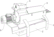
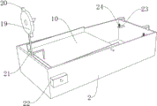
图1为本发明实施例所提供的一种养牛场废弃物集成处理装置的第一种视角三维结构示意图;Fig. 1 is a three-dimensional structure schematic diagram of a first viewing angle of an integrated treatment device for cattle farm waste provided by an embodiment of the present invention;
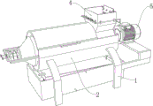
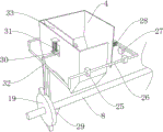
图2为本发明实施例所提供的一种养牛场废弃物集成处理装置的第二种视角三维结构示意图;Fig. 2 is a schematic three-dimensional structural diagram of a second viewing angle of an integrated treatment device for cattle farm waste provided by an embodiment of the present invention;
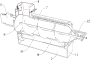
图3为本发明实施例所提供的一种养牛场废弃物集成处理装置的剖视结构示意图;Fig. 3 is a schematic cross-sectional structure diagram of an integrated treatment device for cattle farm waste provided by an embodiment of the present invention;
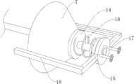
图4为本发明实施例所提供的一种养牛场废弃物集成处理装置的压紧机构结构示意图;Fig. 4 is a structural schematic diagram of a compacting mechanism of a cattle farm waste integrated treatment device provided by an embodiment of the present invention;
图5为本发明实施例所提供的一种养牛场废弃物集成处理装置的筛盒安装结构示意图;Fig. 5 is a schematic diagram of the installation structure of a screen box of a cattle farm waste integrated treatment device provided by an embodiment of the present invention;
图6为本发明实施例所提供的一种养牛场废弃物集成处理装置的敲击组件结构示意图;Fig. 6 is a structural schematic diagram of a knocking component of an integrated treatment device for cattle farm waste provided by an embodiment of the present invention;
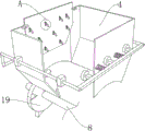
图7为本发明实施例所提供的一种养牛场废弃物集成处理装置的图6的另一种视角结构示意图;Fig. 7 is a structural schematic diagram of another perspective of Fig. 6 of an integrated treatment device for cattle farm waste provided by an embodiment of the present invention;
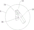
图8为本发明实施例所提供的一种养牛场废弃物集成处理装置的图7中A点放大结构示意图。Fig. 8 is a schematic diagram showing the enlarged structure of point A in Fig. 7 of an integrated treatment device for cattle farm waste provided by an embodiment of the present invention.
附图标记:Reference signs:
1、机架;2、收集盒;3、盖板;4、存料桶;5、电机;7、滤筒;8、驱动轴;9、排液口;10、筛盒;11、螺旋叶片;12、压紧机构;14、顶板;15、调节板;16、第三弹簧;17、螺纹杆;18、延伸架;19、驱动盘;20、第一楔形块;21、第一压杆;22、存渣盒;23、安装板;24、第一弹簧;25、导向块;26、推动架;27、锤头;28、拉簧;29、第二楔形块;30、滑块;31、第二弹簧;32、顶架;33、滑动板;34、安装座;35、下料架;36、橡胶杆。1. Rack; 2. Collection box; 3. Cover plate; 4. Storage barrel; 5. Motor; 7. Filter cartridge; 8. Drive shaft; 9. Drain port; 10. Screen box; 11. Spiral blade ; 12, pressing mechanism; 14, top plate; 15, adjustment plate; 16, the third spring; 17, threaded rod; 18, extension frame; 19, drive plate; ; 31, the second spring; 32, the top frame; 33, the sliding plate; 34, the mounting seat; 35, the blanking frame; 36, the rubber rod.
实施方式Implementation
下面结合本发明实施例中的附图对本发明实施例进行描述。Embodiments of the present invention will be described below with reference to the drawings in the embodiments of the present invention.
实施例Example
参照图1-图8,一种养牛场废弃物集成处理装置,包括:机架1,机架1的顶部固定连接有滤筒7,滤筒7的一端转动连接有贯穿的驱动轴8,驱动轴8的圆周固定连接有送料用的螺旋叶片11,螺旋叶片11位于滤筒7内,滤筒7的出料端为锥形,限制物料的下料速度,使滤筒7内的废弃物产生过一定的压力,进而对固液进行风力,机架1的一侧固定连接有电机5,电机5输出轴的一端与驱动轴8相固定,机架1的一端设有控制下料用的压紧机构12;Referring to Fig. 1-Fig. 8, an integrated waste treatment device for cattle farms comprises: a
机架1的底部固定连接有收集盒2,收集盒2的两侧内壁之间转动连接有筛盒10,机架1的底部开设有排液口9,筛盒10位于排液口9的下方,收集盒2的一侧内壁固定连接有两个安装板23,两个安装板23的顶部均固定连接有第一弹簧24,第一弹簧24的另一端均与筛盒10的底部相固定,驱动轴8的圆周固定连接有驱动盘19,驱动盘19的圆周固定连接有第一楔形块20,收集盒2的一侧内壁滑动连接有第一压杆21,第一压杆21的顶部与驱动盘19接触,第一压杆21的底部与筛盒10接触,筛盒10在移动后,能够在第一弹簧24的推动下复位,使筛盒10快速抖动,防止杂质堆积在筛盒10上,杂质在持续的抖动下落入到存渣盒22上,方便人们进行收集进行二次处理,收集盒2的一侧固定连接有度筛盒10进行限位用的限位架,收集盒2的一侧开设有插口,插口内插接有存渣盒22,存渣盒22位于筛盒10的下方,存渣盒22方便人们对杂质的收集;The bottom of the
存料机构,存料机构设置在机架1的顶部用于对废弃物进行暂存。The material storage mechanism is arranged on the top of the
实施例Example
参照图1-图8,一种养牛场废弃物集成处理装置,包括:Referring to Figure 1-Figure 8, an integrated treatment device for cattle farm waste, including:
机架1,机架1的顶部固定连接有滤筒7,滤筒7的一端转动连接有贯穿的驱动轴8,驱动轴8的圆周固定连接有送料用的螺旋叶片11,螺旋叶片11位于滤筒7内,滤筒7的出料端为锥形,限制物料的下料速度,使滤筒7内的废弃物产生过一定的压力,进而对固液进行风力,机架1的一侧固定连接有电机5,电机5输出轴的一端与驱动轴8相固定,机架1的一端设有控制下料用的压紧机构12,机架1的顶部转动连接有盖板3,盖板3防止液体迸溅;
机架1的底部固定连接有收集盒2,收集盒2的一侧设有视窗,视窗方便人们观看液体的液位,收集盒2的两侧内壁之间转动连接有筛盒10,机架1的底部开设有排液口9,筛盒10位于排液口9的下方,收集盒2的一侧内壁固定连接有两个安装板23,两个安装板23的顶部均固定连接有第一弹簧24,第一弹簧24的另一端均与筛盒10的底部相固定,驱动轴8的圆周固定连接有驱动盘19,驱动盘19的圆周固定连接有第一楔形块20,收集盒2的一侧内壁滑动连接有第一压杆21,第一压杆21的顶部与驱动盘19接触,第一压杆21的底部与筛盒10接触,筛盒10在移动后,能够在第一弹簧24的推动下复位,使筛盒10快速抖动,防止杂质堆积在筛盒10上,杂质在持续的抖动下落入到存渣盒22上,方便人们进行收集进行二次处理,收集盒2的一侧固定连接有度筛盒10进行限位用的限位架,收集盒2的一侧开设有插口,插口内插接有存渣盒22,存渣盒22位于筛盒10的下方,存渣盒22方便人们对杂质的收集;The bottom of the
存料机构,存料机构设置在机架1的顶部用于对废弃物进行暂存。The material storage mechanism is arranged on the top of the
参照图3,存料结构包括存料桶4,存料桶4固定连接在机架1的顶部,存料桶4的底部与滤筒7固定连通,存料桶4用于对原料的暂存,存料桶4的两侧分别设有防止堵料用的送料组件和敲击组件。Referring to Figure 3, the material storage structure includes a
参照图5和图6,敲击组件包括多个导向块25和第二楔形块29,多个导向块25分别固定连接有存料桶4的两侧外壁,多个导向块25之间滑动连接有推动架26,推动架26与存料桶4之间固定连接有拉簧28,推动架26的一侧固定连接有锤头27,锤头27与存料桶4接触,第二楔形块29固定连接在驱动盘19的一侧,推动架26的底部位于驱动盘19的一侧,第二楔形块29在转动时与推动架26接触,推动架26带动锤头27远离存料桶4,随后在拉簧28的拉动下方复位,对存料桶4进行锤击,进一步防止原料堵塞。Referring to Fig. 5 and Fig. 6, the percussion assembly includes a plurality of guide blocks 25 and a
参照图7和图8,送料组件包括开设在存料桶4一侧的滑道,滑道内滑动连接有滑块30,滑块30与存料桶4之间固定连接有第二弹簧31,滑块30的一侧固定连接有顶架32,顶架32与驱动盘19的圆周接触,滑块30的一侧固定连接有滑动板33,滑动板33的一侧固定连接有多个安装座34,安装座34内均转动连接有下料架35,下料架35与安装座34之间均固定连接有橡胶杆36,在滑动板33进行上下移动的过程中,利用下料架35的转动,使其对原料进行推送,与锤头27的配合,进一步提高下料效果。Referring to Fig. 7 and Fig. 8, the feeding assembly includes a slideway provided on one side of the
参照图4,压紧机构12包括延伸架18,延伸架18的一侧螺纹连接有两个螺纹杆17,两个螺纹杆17的另一端转动连接有同一个调节板15,调节板15的一侧固定连接有第三弹簧16,第三弹簧16的另一端固定连接有对滤筒7出料进行封堵用的顶板14,转动螺纹杆17,螺纹杆17推动调节板15移动,从而改变调节板15和顶板14之间的距离,进而改变第三弹簧16的弹力和顶板14的压紧力,改变固液的分离情况。With reference to Fig. 4, pressing
本发明还提出一种养牛场废弃物集成处理装置的处理方法,包括以下步骤:The present invention also proposes a processing method of an integrated processing device for waste in a cattle farm, which includes the following steps:
S1:将废弃物放入存料桶4中,然后启动电机5,电机5带动驱动轴8和螺旋叶片11对废弃物进行输送,由于滤筒7的一端直径小,同时废弃物在顶板14的挤压作用下废弃物在滤筒7内受到挤压,从而实现固液分离,液体通过滤筒7和排液口9向下落,再进筛盒10的过滤后,落入到收集盒2中方便人们的收集,而去液后的固体将持续的挤压下将顶板14顶开,进而排出,排出的原料加入尿素,然后进行堆肥处理;S1: Put the waste into the
S2:在驱动轴8转动的同时带动驱动盘19转动,驱动盘19带动第一楔形块20和第二楔形块29转动,第一楔形块20与第一压杆21接触,将第一压杆21向下压制,第一压杆21带动筛盒10的一端向下移动,随后第一楔形块20与第一压杆21脱离接触,筛盒10在第一弹簧24的推动下复位,使筛盒10快速抖动,防止杂质堆积在筛盒10上,杂质在持续的抖动下落入到存渣盒22上,方便人们进行收集进行二次处理;S2: Drive the
S3:第一楔形块20在转动时还与顶架32接触,利用顶架32将滑块30向上顶起,进而使滑动板33向上移动,滑动板33带动下料架35向上移动,下料架35与废弃物接触时,由于下料架35被橡胶杆36支撑,从而在受到阻力时发生转动,随后在滑动板33在向下移动时,下料架35在受到废弃物的阻挡,使下料架35复位,将废弃物向下推送,防止原料堵塞;S3: The first wedge-shaped
S4:第二楔形块29在转动时与推动架26接触,推动架26带动锤头27远离存料桶4,随后在拉簧28的拉动下方复位,对存料桶4进行锤击,进一步防止原料堵塞;S4: The
S5:需要调整废弃物的分离情况时,转动螺纹杆17,螺纹杆17推动调节板15移动,从而改变调节板15和顶板14之间的距离,进而改变第三弹簧16的弹力和顶板14的压紧力,改变固液的分离情况。S5: When it is necessary to adjust the separation of waste, turn the threaded
Claims (9)
Priority Applications (1)
| Application Number | Priority Date | Filing Date | Title |
|---|---|---|---|
| CN202310339148.7A CN116102229B (en) | 2023-04-01 | 2023-04-01 | Cattle farm waste integrated treatment device and treatment method thereof |
Applications Claiming Priority (1)
| Application Number | Priority Date | Filing Date | Title |
|---|---|---|---|
| CN202310339148.7A CN116102229B (en) | 2023-04-01 | 2023-04-01 | Cattle farm waste integrated treatment device and treatment method thereof |
Publications (2)
| Publication Number | Publication Date |
|---|---|
| CN116102229A true CN116102229A (en) | 2023-05-12 |
| CN116102229B CN116102229B (en) | 2025-09-19 |
Family
ID=86265768
Family Applications (1)
| Application Number | Title | Priority Date | Filing Date |
|---|---|---|---|
| CN202310339148.7A Active CN116102229B (en) | 2023-04-01 | 2023-04-01 | Cattle farm waste integrated treatment device and treatment method thereof |
Country Status (1)
| Country | Link |
|---|---|
| CN (1) | CN116102229B (en) |
Cited By (1)
| Publication number | Priority date | Publication date | Assignee | Title |
|---|---|---|---|---|
| CN118987774A (en) * | 2024-10-18 | 2024-11-22 | 山西农业大学 | Dewatering device and dewatering method for microbial organic fertilizer production |
Citations (2)
| Publication number | Priority date | Publication date | Assignee | Title |
|---|---|---|---|---|
| JP6811366B1 (en) * | 2020-02-14 | 2021-01-13 | ▲し▼博翰帥労保用品有限公司 | Wastewater treatment equipment based on the pressurized flotation method |
| CN112495036A (en) * | 2021-02-03 | 2021-03-16 | 烟台工程职业技术学院(烟台市技师学院) | Chemical test waste treatment device |
-
2023
- 2023-04-01 CN CN202310339148.7A patent/CN116102229B/en active Active
Patent Citations (2)
| Publication number | Priority date | Publication date | Assignee | Title |
|---|---|---|---|---|
| JP6811366B1 (en) * | 2020-02-14 | 2021-01-13 | ▲し▼博翰帥労保用品有限公司 | Wastewater treatment equipment based on the pressurized flotation method |
| CN112495036A (en) * | 2021-02-03 | 2021-03-16 | 烟台工程职业技术学院(烟台市技师学院) | Chemical test waste treatment device |
Cited By (1)
| Publication number | Priority date | Publication date | Assignee | Title |
|---|---|---|---|---|
| CN118987774A (en) * | 2024-10-18 | 2024-11-22 | 山西农业大学 | Dewatering device and dewatering method for microbial organic fertilizer production |
Also Published As
| Publication number | Publication date |
|---|---|
| CN116102229B (en) | 2025-09-19 |
Similar Documents
| Publication | Publication Date | Title |
|---|---|---|
| CN210367402U (en) | Extrusion mechanism and excrement dry-wet separator | |
| CN111377586A (en) | Livestock and poultry excrement dewatering equipment | |
| CN112344666A (en) | Be used for kitchen discarded object extrusion dewatering device | |
| CN116102229B (en) | Cattle farm waste integrated treatment device and treatment method thereof | |
| CN107873526A (en) | Livestock and poultry ecological cultivation system and cultural method | |
| US4592275A (en) | Method and apparatus for recovery of useful feed values from animal waste | |
| CN116621628A (en) | Harmless treatment method and treatment device for livestock and poultry manure | |
| CN113683282B (en) | Excrement recycling device for animal husbandry | |
| CN117923956B (en) | Livestock manure composting device and composting method thereof | |
| CN211074806U (en) | Bidirectional extrusion type solid-liquid separator | |
| CN108848968A (en) | The processing unit (plant) of impurity in raw material can be removed | |
| CN108378401B (en) | Sheep feed processing device | |
| CN218890808U (en) | Traditional chinese medicine screening installation | |
| CN215223843U (en) | A livestock feeding device | |
| DE102011120504A1 (en) | Solid-liquid treatment of liquid starting substrate, preferably e.g. slurry or fermentation residue, comprises pre-compressing starting substrate with filter aid to a pourable material, separating liquid phase and pressing the bulk goods | |
| CN215917650U (en) | Crushing apparatus is broken up to fodder | |
| CN212504527U (en) | Livestock and poultry manure processor | |
| CN214088213U (en) | A excrement and urine sorter for livestock-raising | |
| CN206778008U (en) | A kind of fowl and animal excrement forces solid-liquid separating machine | |
| CN223970372U (en) | Particle screening device for feed processing convenient to use | |
| RU2728467C1 (en) | Conveyor press for bird droppings dehydration | |
| DE875296C (en) | Method and device for the production of animal feed | |
| CN220309744U (en) | Extraction and concentration equipment | |
| CN119216069B (en) | Animal husbandry waste treatment and recycling equipment | |
| CN220590200U (en) | A fodder grinding device for feed processing |
Legal Events
| Date | Code | Title | Description |
|---|---|---|---|
| PB01 | Publication | ||
| PB01 | Publication | ||
| SE01 | Entry into force of request for substantive examination | ||
| SE01 | Entry into force of request for substantive examination | ||
| GR01 | Patent grant | ||
| GR01 | Patent grant |