CN116100726A - Plastic body processing and forming mechanism based on hydraulic transmission - Google Patents
Plastic body processing and forming mechanism based on hydraulic transmission Download PDFInfo
- Publication number
- CN116100726A CN116100726A CN202310388850.2A CN202310388850A CN116100726A CN 116100726 A CN116100726 A CN 116100726A CN 202310388850 A CN202310388850 A CN 202310388850A CN 116100726 A CN116100726 A CN 116100726A
- Authority
- CN
- China
- Prior art keywords
- hydraulic
- module
- plastic
- motor
- fixed
- Prior art date
- Legal status (The legal status is an assumption and is not a legal conclusion. Google has not performed a legal analysis and makes no representation as to the accuracy of the status listed.)
- Granted
Links
- 229920003023 plastic Polymers 0.000 title claims abstract description 77
- 239000004033 plastic Substances 0.000 title claims abstract description 77
- 230000005540 biological transmission Effects 0.000 title claims abstract description 10
- 238000000465 moulding Methods 0.000 claims description 27
- 239000000463 material Substances 0.000 claims description 20
- 238000001816 cooling Methods 0.000 claims description 16
- 238000003756 stirring Methods 0.000 claims description 11
- 238000007710 freezing Methods 0.000 claims description 8
- 230000008014 freezing Effects 0.000 claims description 8
- 238000007711 solidification Methods 0.000 claims description 8
- 230000008023 solidification Effects 0.000 claims description 8
- 230000006835 compression Effects 0.000 claims description 5
- 238000007906 compression Methods 0.000 claims description 5
- 239000000110 cooling liquid Substances 0.000 claims description 5
- 244000309464 bull Species 0.000 claims 3
- 230000003028 elevating effect Effects 0.000 claims 2
- 229920000034 Plastomer Polymers 0.000 claims 1
- 238000007493 shaping process Methods 0.000 description 4
- 238000001125 extrusion Methods 0.000 description 3
- 238000004519 manufacturing process Methods 0.000 description 3
- 230000005611 electricity Effects 0.000 description 2
- 238000005265 energy consumption Methods 0.000 description 2
- 239000007788 liquid Substances 0.000 description 2
- 238000000034 method Methods 0.000 description 2
- 229920003002 synthetic resin Polymers 0.000 description 2
- 230000009286 beneficial effect Effects 0.000 description 1
- 150000001875 compounds Chemical class 0.000 description 1
- 238000010586 diagram Methods 0.000 description 1
- 230000000694 effects Effects 0.000 description 1
- 238000012986 modification Methods 0.000 description 1
- 230000004048 modification Effects 0.000 description 1
- 229920000642 polymer Polymers 0.000 description 1
- 238000003825 pressing Methods 0.000 description 1
- 239000000057 synthetic resin Substances 0.000 description 1
Images
Classifications
-
- B—PERFORMING OPERATIONS; TRANSPORTING
- B29—WORKING OF PLASTICS; WORKING OF SUBSTANCES IN A PLASTIC STATE IN GENERAL
- B29C—SHAPING OR JOINING OF PLASTICS; SHAPING OF MATERIAL IN A PLASTIC STATE, NOT OTHERWISE PROVIDED FOR; AFTER-TREATMENT OF THE SHAPED PRODUCTS, e.g. REPAIRING
- B29C43/00—Compression moulding, i.e. applying external pressure to flow the moulding material; Apparatus therefor
- B29C43/02—Compression moulding, i.e. applying external pressure to flow the moulding material; Apparatus therefor of articles of definite length, i.e. discrete articles
-
- B—PERFORMING OPERATIONS; TRANSPORTING
- B29—WORKING OF PLASTICS; WORKING OF SUBSTANCES IN A PLASTIC STATE IN GENERAL
- B29C—SHAPING OR JOINING OF PLASTICS; SHAPING OF MATERIAL IN A PLASTIC STATE, NOT OTHERWISE PROVIDED FOR; AFTER-TREATMENT OF THE SHAPED PRODUCTS, e.g. REPAIRING
- B29C43/00—Compression moulding, i.e. applying external pressure to flow the moulding material; Apparatus therefor
- B29C43/32—Component parts, details or accessories; Auxiliary operations
- B29C43/52—Heating or cooling
-
- B—PERFORMING OPERATIONS; TRANSPORTING
- B29—WORKING OF PLASTICS; WORKING OF SUBSTANCES IN A PLASTIC STATE IN GENERAL
- B29C—SHAPING OR JOINING OF PLASTICS; SHAPING OF MATERIAL IN A PLASTIC STATE, NOT OTHERWISE PROVIDED FOR; AFTER-TREATMENT OF THE SHAPED PRODUCTS, e.g. REPAIRING
- B29C43/00—Compression moulding, i.e. applying external pressure to flow the moulding material; Apparatus therefor
- B29C43/32—Component parts, details or accessories; Auxiliary operations
- B29C43/58—Measuring, controlling or regulating
-
- Y—GENERAL TAGGING OF NEW TECHNOLOGICAL DEVELOPMENTS; GENERAL TAGGING OF CROSS-SECTIONAL TECHNOLOGIES SPANNING OVER SEVERAL SECTIONS OF THE IPC; TECHNICAL SUBJECTS COVERED BY FORMER USPC CROSS-REFERENCE ART COLLECTIONS [XRACs] AND DIGESTS
- Y02—TECHNOLOGIES OR APPLICATIONS FOR MITIGATION OR ADAPTATION AGAINST CLIMATE CHANGE
- Y02W—CLIMATE CHANGE MITIGATION TECHNOLOGIES RELATED TO WASTEWATER TREATMENT OR WASTE MANAGEMENT
- Y02W30/00—Technologies for solid waste management
- Y02W30/50—Reuse, recycling or recovery technologies
- Y02W30/62—Plastics recycling; Rubber recycling
Landscapes
- Engineering & Computer Science (AREA)
- Mechanical Engineering (AREA)
- Shaping Metal By Deep-Drawing, Or The Like (AREA)
- Moulds For Moulding Plastics Or The Like (AREA)
Abstract
The invention belongs to the technical field of plastic processing based on hydraulic transmission, and particularly relates to a plastic processing and forming mechanism based on hydraulic transmission, which comprises a plastic processing and forming mechanism and an intelligent forming system, wherein the plastic processing and forming mechanism comprises a workbench and a hydraulic press, the hydraulic press is arranged above the workbench, the hydraulic press comprises a base and a fixed plate, the base is fixedly arranged above the workbench, a plurality of guide posts are fixedly arranged between the base and the fixed plate, a hydraulic cylinder is fixedly arranged above the fixed plate, an upper die is fixedly arranged below the hydraulic cylinder, the upper die is in sliding connection with the guide posts, a lower die is fixedly arranged above the base, the intelligent forming system is electrically connected with the hydraulic cylinder, a driving cavity is fixedly arranged above the left side of the workbench, and a hydraulic cavity is fixedly arranged on the inner wall of the driving cavity.
Description
Technical Field
The invention belongs to the technical field of plastic body processing based on hydraulic transmission, and particularly relates to a plastic body processing and forming mechanism based on hydraulic transmission.
Background
The plastics that we generally use are not a single component, and are formulated from a number of materials. Among them, a polymer (or synthetic resin) is a main component of plastics, and various auxiliary materials are added to a polymer compound in order to improve the properties of plastics, and the higher the solidification point, the more difficult the solidification of such plastics is when the plastics are in a liquid state.
The hydraulic transmission plastic body processing and forming mechanism adopted by the technical scheme can ensure the forming quality and improve the forming efficiency through intelligent forming, and meanwhile, the forming modes are automatically selected for plastics with different solidifying points, so that the forming quality is further improved. This phenomenon is a problem to be solved by those skilled in the art.
Disclosure of Invention
The invention aims to provide a plastic body processing and forming mechanism based on hydraulic transmission, so as to solve the problems in the background art.
In order to solve the technical problems, the invention provides the following technical scheme: the utility model provides a plastic body machine-shaping mechanism based on hydraulic drive, includes plastic body machine-shaping mechanism and intelligent molding system, plastic body machine-shaping mechanism includes workstation and hydraulic press, the hydraulic press is installed in the top of workstation, the hydraulic press includes base and fixed plate, base fixed mounting is in the top of workstation, fixed mounting has a plurality of guide posts between base and the fixed plate, the fixed plate top is fixed with the pneumatic cylinder, the below of pneumatic cylinder is fixed with the mould, go up mould and guide pillar sliding connection, the base top is fixed with the lower mould, intelligent molding system and pneumatic cylinder electric connection.
The invention further describes that a driving cavity is fixed above the left side of the workbench, a hydraulic cavity is fixed on the inner wall of the driving cavity, a hydraulic plate is connected on the inner wall of the hydraulic cavity in a sliding mode, a groove is formed above the lower die, the inside of the hydraulic plate is hollow, the hydraulic cavity is connected with an inner pipeline of the lower die, the hydraulic plate is fixedly connected with the upper die, and cooling liquid is filled below the hydraulic plate.
According to the invention, a sliding rod is fixed below the hydraulic plate, a toothed plate is fixed on the outer side of the lower end of the sliding rod, the toothed plate is arranged below the hydraulic cavity, a gear is meshed with the left side of the toothed plate, a rotating rod is sleeved in the gear, the rotating rod is fixedly connected with the inner wall of the driving cavity, a torsion sensor is arranged in the gear, a torsion spring is fixed between the rotating rod and the gear, a cooling intensity lifting mechanism is arranged in the lower die, and the torsion sensor is electrically connected with the cooling intensity lifting mechanism.
The invention further discloses that the torsion sensor is internally provided with a torsion sensing module and a driving module, the torsion sensing module is electrically connected with the driving module, the cooling strength lifting mechanism comprises a motor and a stirring rod, the motor is fixedly arranged on the inner wall of the lower die, the stirring rod is fixedly connected with the motor, the driving module is electrically connected with the motor, the torsion sensing module is used for sensing the stress of the torsion spring, and the driving module is used for controlling the rotating speed of the motor.
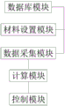
The intelligent forming system comprises a database module, a material setting module, a data acquisition module, a calculation module and a control module, wherein the data acquisition module is electrically connected with the database module and the material setting module respectively, the calculation module is electrically connected with the data acquisition module, the control module is electrically connected with the calculation module, and the control module is electrically connected with the hydraulic cylinder;
the database module is used for storing solidifying points of various plastics, the material setting module is used for setting the types of materials by operators, the data acquisition module is used for calling the solidifying points of the plastics from the database according to the set types of the materials, the calculation module is used for calculating, and the control module is used for controlling the operation power of the hydraulic cylinder according to the calculation result.
The invention further describes that the intelligent molding system comprises the following operation steps:
s1, operating an intelligent molding system, and starting molding;
step S2, the data acquisition module is used for calling the solidifying point of the plastic from the database according to the set material types and calculating, the control module controls the operation power of the hydraulic cylinder according to the calculation result, the plastic solidifying point is high, and the step S3 is carried out, otherwise the step S4 is carried out;
s3, the torsion sensing module senses the stress of the torsion spring, and the rotating speed of the motor is controlled through the driving module, so that the plastic solidification speed is further increased;
and S4, finishing the molding of single plastic, and repeating the steps S1 to S3 when the continuous molding work is finished.
The invention further illustrates that in the step S2, the lower the plastic solidifying point is, the easier the plastic is solidified, and the greater the operating power of the hydraulic cylinder is:
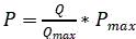
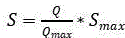


The invention further describes that, in the step S3, when When (I)>
 For the normal operating power of pneumatic cylinder, the effort of torsional spring to torsion inductor is big, and at this moment drive module control motor rotates to according to effort size control motor's rotational speed:
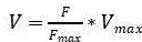


Compared with the prior art, the invention has the following beneficial effects: according to the plastic processing and forming mechanism, the hydraulic plate moves downwards to drive the sliding rod to move downwards, the sliding rod drives the toothed plate to move downwards, the toothed plate drives the gear to rotate through meshing, in the process of gear rotation, the torsion spring is pulled to deform under stress, meanwhile, the torsion force sensing module in the torsion sensor senses the torsion force, when the plastic solidifying point is higher, the hydraulic cylinder drives the upper die to have larger extrusion force on the plastic, so that the distance of the downward movement of the hydraulic plate is larger, the toothed plate drives the gear to rotate to increase in amplitude, after the torsion sensing module senses the torsion force to a certain extent, the motor is driven to rotate through the driving module, the stirring rod is driven to rotate by the motor, and therefore cooling efficiency is increased, cooling speed is further increased, the plastic is fully cooled and formed, and production efficiency is accelerated.
Drawings
The accompanying drawings are included to provide a further understanding of the invention and are incorporated in and constitute a part of this specification, illustrate the invention and together with the embodiments of the invention, serve to explain the invention. In the drawings:
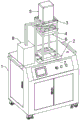
FIG. 1 is a schematic view of the overall structure of the present invention;
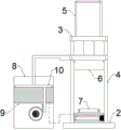
FIG. 2 is a schematic plan view of the hydraulic machine and drive chamber of the present invention;
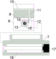
FIG. 3 is a schematic view of the connection between the hydraulic chamber and the lower die pipeline of the present invention;
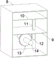
FIG. 4 is a schematic view of the internal structure of the drive chamber of the present invention;
FIG. 5 is a schematic flow diagram of the intelligent molding system of the present invention;
in the figure: 1. a work table; 2. a base; 3. a fixing plate; 4. a guide post; 5. a hydraulic cylinder; 6. an upper die; 7. a lower die; 8. a drive chamber; 9. a hydraulic chamber; 10. a hydraulic plate; 11. a slide bar; 12. a toothed plate; 13. a gear; 14. a rotating rod; 15. a torque sensor; 16. a torsion spring; 17. a motor; 18. stirring rod.
Detailed Description
The technical scheme of the present invention is further described in non-limiting detail below with reference to the preferred embodiments and the accompanying drawings. It will be apparent that the described embodiments are only some, but not all, embodiments of the invention. All other embodiments, which can be made by those skilled in the art based on the embodiments of the invention without making any inventive effort, are intended to be within the scope of the invention.
Referring to fig. 1-5, the present invention provides the following technical solutions: the plastic body processing and forming mechanism based on hydraulic transmission comprises a plastic body processing and forming mechanism and an intelligent forming system, wherein the plastic body processing and forming mechanism comprises a workbench 1 and a hydraulic press, the hydraulic press is arranged above the workbench 1, the hydraulic press comprises a base 2 and a fixed plate 3, the base 2 is fixedly arranged above the workbench 1, a plurality of guide posts 4 are fixedly arranged between the base 2 and the fixed plate 3, a hydraulic cylinder 5 is fixedly arranged above the fixed plate 3, an upper die 6 is fixedly arranged below the hydraulic cylinder 5, the upper die 6 is in sliding connection with the guide posts 4, a lower die 7 is fixedly arranged above the base 2, the intelligent forming system is electrically connected with the hydraulic cylinder 5, an operator injects liquid plastic into the lower die 7, then the intelligent forming system is driven to operate by electricity, the intelligent forming system is driven by electricity to control the hydraulic cylinder 5 to operate, the hydraulic cylinder 5 is driven by the hydraulic pressure to enable the upper die 6 to move downwards along the guide posts 4 until the upper die 6 is in contact with the plastic and extrudes the plastic, the upper die 6 and the lower die 7 extrudes the plastic, so that the intelligent forming system controls the power of the hydraulic cylinder 5, and the solidification point of the plastic is not easy to change when the extrusion strength of the upper die 6 is higher;
the upper part of the left side of the workbench 1 is fixedly provided with a driving cavity 8, the inner wall of the driving cavity 8 is fixedly provided with a hydraulic cavity 9, the inner wall of the hydraulic cavity 9 is slidably connected with a hydraulic plate 10, a groove is formed above the lower die 7, the inside of the hydraulic plate is hollow, the hydraulic cavity 9 is connected with the inner pipeline of the lower die 7, the hydraulic plate 10 is fixedly connected with the upper die 6, and the lower part of the hydraulic plate 10 is filled with cooling liquid;
a slide bar 11 is fixed below the hydraulic plate 10, a toothed plate 12 is fixed outside the lower end of the slide bar 11, the toothed plate 12 is arranged below the hydraulic cavity 9, a gear 13 is meshed with the left side of the toothed plate 12, a rotating rod 14 is sleeved inside the gear 13, the rotating rod 14 is fixedly connected with the inner wall of the driving cavity 8, a torsion sensor 15 is arranged inside the gear 13, a torsion spring 16 is fixed between the rotating rod 14 and the gear 13, a cooling intensity lifting mechanism is arranged inside the lower die 7, and the torsion sensor 15 is electrically connected with the cooling intensity lifting mechanism;
the torque sensor 15 is internally provided with a torque sensing module and a driving module, the torque sensing module is electrically connected with the driving module, the cooling strength lifting mechanism comprises a motor 17 and a stirring rod 18, the motor 17 is fixedly arranged on the inner wall of the lower die 7, the stirring rod 18 is fixedly connected with the motor 17, the driving module is electrically connected with the motor 17, the torque sensing module is used for sensing the stress of the torsion spring 16, and the driving module is used for controlling the rotating speed of the motor 17;
through the steps, the hydraulic plate 10 moves downwards to drive the slide bar 11 to move downwards, the slide bar 11 drives the toothed plate 12 to move downwards, the toothed plate 12 drives the gear 13 to rotate through meshing, in the rotation process of the gear 13, the torsion spring 16 is pulled to deform under force, simultaneously, a torsion sensing module in the torsion sensor 15 senses the torsion, when the plastic solidifying point is higher, the hydraulic cylinder 5 drives the upper die 6 to extrude plastic with larger force, so that the downward moving distance of the hydraulic plate 10 is larger, the toothed plate 12 drives the gear 13 to rotate to an increased extent, after the torsion sensing module senses the torsion to a certain extent, the motor 17 rotates through the driving module, the motor 17 rotates to drive the stirring rod 18 to rotate, and the stirring rod 18 stirs the cooling liquid entering the lower die 7, thereby increasing the cooling efficiency, further accelerating the cooling speed, fully cooling and shaping the plastic, and accelerating the production efficiency;
the intelligent forming system comprises a database module, a material setting module, a data acquisition module, a calculation module and a control module, wherein the data acquisition module is respectively and electrically connected with the database module and the material setting module, the calculation module is electrically connected with the data acquisition module, the control module is electrically connected with the calculation module, and the control module is electrically connected with the hydraulic cylinder 5;
the database module is used for storing solidifying points of various plastics, the material setting module is used for setting the types of materials by an operator, the data acquisition module is used for calling the solidifying points of the plastics from the database according to the set types of the materials, the calculation module is used for calculating, and the control module is used for controlling the operation power of the hydraulic cylinder 5 according to the calculation result;
the intelligent molding system comprises the following operation steps:
s1, operating an intelligent molding system, and starting molding;
step S2, the data acquisition module is used for calling the solidifying point of the plastic from the database according to the set material types and calculating, the control module controls the operation power of the hydraulic cylinder 5 according to the calculation result, the plastic solidifying point is high, and the step S3 is entered, and otherwise the step S4 is entered;
step S3, the torsion sensing module senses the stress of the torsion spring 16, and the rotating speed of the motor 17 is controlled through the driving module, so that the plastic solidification speed is further increased;
step S4, finishing the molding of single plastic, and repeating the steps S1 to S3 when the continuous molding work is finished;
in step S2, the lower the plastic solidification point is, the easier it is to solidify, and the greater the operating power of the hydraulic cylinder 5 is:
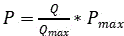
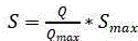


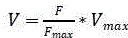
aiming at plastics with low solidifying point, the plastic is easier to solidify, so that the hydraulic cylinder 5 drives the upper die 6 to extrude the plastic with smaller extruding force and less extruding time, on the one hand, the operation energy consumption of the hydraulic cylinder 5 can be reduced, on the other hand, the plastic is prevented from being damaged by excessive extrusion to reduce the molding quality, and aiming at plastics with high solidifying point, the extruding force and the extruding time of the plastic are increased, so that the plastic can be fully shaped;
in step S3, when When (I)>
 For the normal operation power of the
hydraulic cylinder 5, the torsion spring 16 has a large acting force on the torsion sensor 15, and at this time, the driving module controls the motor 17 to rotate, and controls the rotating speed of the motor 17 according to the acting force: />
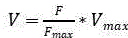


the acting force applied to the torsion spring 16 is smaller for plastics with low freezing point, at this time, the motor 17 is in a stop running state, the plastics solidify fast, and the cooling speed is not required to be increased, so that the energy consumption is further reduced, the production cost is reduced, and for plastics with high freezing point, the higher the freezing point is, the faster the motor 17 rotates and the rotating speed is, so that the cooling liquid shakes in the lower die 7, the cooling effect is improved, and the solidification speed of the plastics is increased.
In the description of the present invention, it should be understood that the directions or positional relationships indicated by the terms "upper", "lower", "front", "rear", "left", "right", etc. are based on the directions or positional relationships shown in the drawings, are merely for convenience of describing the present invention, and do not indicate or imply that the apparatus or elements referred to must have a specific orientation, be constructed and operated in a specific orientation, and thus should not be construed as limiting the present invention.
Finally, it should be pointed out that: the above embodiments are only for illustrating the technical solution of the present invention, and are not limiting. Although the invention has been described in detail with reference to the foregoing embodiments, it will be understood by those of ordinary skill in the art that: the technical solutions described in the foregoing embodiments may be modified or some technical features may be equivalently replaced, and these modifications or replacements do not make the essence of the corresponding technical solutions deviate from the spirit and scope of the technical solutions of the embodiments of the present invention.
Claims (8)
1. Plastic processing and forming mechanism based on hydraulic transmission, including plastic processing and forming mechanism and intelligent molding system, its characterized in that: the utility model provides a plastic body processing forming mechanism includes workstation (1) and hydraulic press, the hydraulic press is installed in the top of workstation (1), the hydraulic press includes base (2) and fixed plate (3), base (2) fixed mounting is in the top of workstation (1), fixed mounting has a plurality of guide pillars (4) between base (2) and fixed plate (3), fixed plate (3) top is fixed with pneumatic cylinder (5), the below of pneumatic cylinder (5) is fixed with mould (6), go up mould (6) and guide pillar (4) sliding connection, base (2) top is fixed with lower mould (7), intelligent molding system and pneumatic cylinder (5) electric connection.
2. The hydraulic-drive-based molding machine of claim 1, wherein: the automatic feeding device is characterized in that a driving cavity (8) is fixed above the left side of the workbench (1), a hydraulic cavity (9) is fixed on the inner wall of the driving cavity (8), a hydraulic plate (10) is slidably connected on the inner wall of the hydraulic cavity (9), a groove is formed in the upper portion of the lower die (7), the inside of the lower die is hollow, the hydraulic cavity (9) is connected with an inner pipeline of the lower die (7), the hydraulic plate (10) is fixedly connected with the upper die (6), and cooling liquid is filled below the hydraulic plate (10).
3. The hydraulic-drive-based molding machine of claim 2, wherein: the hydraulic plate (10) below is fixed with slide bar (11), the lower extreme outside of slide bar (11) is fixed with pinion rack (12), pinion rack (12) set up in the below of hydraulic pressure chamber (9), pinion rack (12) left side meshing has gear (13), inside bull stick (14) of having cup jointed of gear (13), the inner wall fixed connection of bull stick (14) and driving chamber (8), the inside of gear (13) is provided with torsion inductor (15), be fixed with torsional spring (16) between bull stick (14) and gear (13), the inside cooling intensity elevating system that is provided with of lower mould (7), torsion inductor (15) and cooling intensity elevating system electric connection.
4. A hydraulic-drive-based plastomer forming mechanism according to claim 3, wherein: the torque force sensor is characterized in that a torque force sensing module and a driving module are arranged inside the torque force sensor (15), the torque force sensing module is electrically connected with the driving module, the cooling strength lifting mechanism comprises a motor (17) and a stirring rod (18), the motor (17) is fixedly arranged on the inner wall of the lower die (7), the stirring rod (18) is fixedly connected with the motor (17), the driving module is electrically connected with the motor (17), and the torque force sensing module is used for sensing the stress of the torsion spring (16), and the driving module is used for controlling the rotating speed of the motor (17).
5. The hydraulic-drive-based molding machine of claim 4, wherein: the intelligent forming system comprises a database module, a material setting module, a data acquisition module, a calculation module and a control module, wherein the data acquisition module is respectively and electrically connected with the database module and the material setting module, the calculation module is electrically connected with the data acquisition module, the control module is electrically connected with the calculation module, and the control module is electrically connected with the hydraulic cylinder (5);
the data base module is used for storing solidifying points of various plastics, the material setting module is used for setting types of materials by operators, the data acquisition module is used for calling the solidifying points of the plastics from the data base according to the set types of the materials, the calculation module is used for calculating, and the control module is used for controlling the operation power of the hydraulic cylinder (5) according to a calculation result.
6. The hydraulic-drive-based molding machine of claim 5, wherein: the intelligent molding system comprises the following operation steps:
s1, operating an intelligent molding system, and starting molding;
step S2, the data acquisition module is used for calling the solidifying point of the plastic from the database according to the set material types and calculating, the control module controls the operation power of the hydraulic cylinder (5) according to the calculation result, the plastic solidifying point is high, and the step S3 is entered, and otherwise the step S4 is entered;
s3, the torsion sensing module senses the stress of the torsion spring (16) and controls the rotating speed of the motor (17) through the driving module, so that the plastic solidification speed is further increased;
and S4, finishing the molding of single plastic, and repeating the steps S1 to S3 when the continuous molding work is finished.
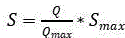
7. The hydraulic-drive-based molding machine of claim 6, wherein: in the step S2, the lower the plastic solidifying point is, the easier the plastic is solidified, and the higher the operating power of the hydraulic cylinder (5) is:



8. The hydraulic-drive-based molding machine of claim 7, wherein: in the step S3, when When (I)>
 For the normal operating power of the hydraulic cylinder (5), the torsion spring (16) has large acting force on the torsion sensor (15), and at the moment, the driving module controls the motor (17) to rotate and controls the rotating speed of the motor (17) according to the acting force:


Priority Applications (1)
| Application Number | Priority Date | Filing Date | Title |
|---|---|---|---|
| CN202310388850.2A CN116100726B (en) | 2023-04-13 | 2023-04-13 | Plastic body processing and forming mechanism based on hydraulic transmission |
Applications Claiming Priority (1)
| Application Number | Priority Date | Filing Date | Title |
|---|---|---|---|
| CN202310388850.2A CN116100726B (en) | 2023-04-13 | 2023-04-13 | Plastic body processing and forming mechanism based on hydraulic transmission |
Publications (2)
| Publication Number | Publication Date |
|---|---|
| CN116100726A true CN116100726A (en) | 2023-05-12 |
| CN116100726B CN116100726B (en) | 2023-08-01 |
Family
ID=86267609
Family Applications (1)
| Application Number | Title | Priority Date | Filing Date |
|---|---|---|---|
| CN202310388850.2A Active CN116100726B (en) | 2023-04-13 | 2023-04-13 | Plastic body processing and forming mechanism based on hydraulic transmission |
Country Status (1)
| Country | Link |
|---|---|
| CN (1) | CN116100726B (en) |
Citations (7)
| Publication number | Priority date | Publication date | Assignee | Title |
|---|---|---|---|---|
| CN211334251U (en) * | 2019-09-18 | 2020-08-25 | 武汉华佰仕科技有限公司 | Silica gel mould production forming device for guide housing |
| CN113021766A (en) * | 2021-04-28 | 2021-06-25 | 深圳市明舟精密制造有限公司 | Bluetooth headset shell rapid cooling forming die and operation method thereof |
| CN215619508U (en) * | 2021-09-02 | 2022-01-25 | 东莞市鹏贝硅材料有限公司 | Efficient forming and extruding mechanism for silicon rubber |
| CN114953510A (en) * | 2022-06-22 | 2022-08-30 | 南通锻压设备如皋有限公司 | Intelligent flexible composite material molding hydraulic machine and control method thereof |
| CN217315667U (en) * | 2022-01-20 | 2022-08-30 | 江西江锻重工有限公司 | Ring blank forging hydraulic press |
| CN115070020A (en) * | 2022-06-21 | 2022-09-20 | 赵全芳 | Gravity casting device based on transient pressure intensity distribution |
| CN115891009A (en) * | 2022-10-13 | 2023-04-04 | 南通景康橡塑有限公司 | A multifunctional rubber diaphragm molding die |
-
2023
- 2023-04-13 CN CN202310388850.2A patent/CN116100726B/en active Active
Patent Citations (7)
| Publication number | Priority date | Publication date | Assignee | Title |
|---|---|---|---|---|
| CN211334251U (en) * | 2019-09-18 | 2020-08-25 | 武汉华佰仕科技有限公司 | Silica gel mould production forming device for guide housing |
| CN113021766A (en) * | 2021-04-28 | 2021-06-25 | 深圳市明舟精密制造有限公司 | Bluetooth headset shell rapid cooling forming die and operation method thereof |
| CN215619508U (en) * | 2021-09-02 | 2022-01-25 | 东莞市鹏贝硅材料有限公司 | Efficient forming and extruding mechanism for silicon rubber |
| CN217315667U (en) * | 2022-01-20 | 2022-08-30 | 江西江锻重工有限公司 | Ring blank forging hydraulic press |
| CN115070020A (en) * | 2022-06-21 | 2022-09-20 | 赵全芳 | Gravity casting device based on transient pressure intensity distribution |
| CN114953510A (en) * | 2022-06-22 | 2022-08-30 | 南通锻压设备如皋有限公司 | Intelligent flexible composite material molding hydraulic machine and control method thereof |
| CN115891009A (en) * | 2022-10-13 | 2023-04-04 | 南通景康橡塑有限公司 | A multifunctional rubber diaphragm molding die |
Also Published As
| Publication number | Publication date |
|---|---|
| CN116100726B (en) | 2023-08-01 |
Similar Documents
| Publication | Publication Date | Title |
|---|---|---|
| CN201720992U (en) | Fully electrical double-screw injection molding machine | |
| CN213618178U (en) | Hybrid injection molding machine | |
| CN219076454U (en) | Injection molding equipment convenient to control material velocity of flow | |
| CN203680650U (en) | Small-size multi-color vertical type precision injection molding machine | |
| CN116100726B (en) | Plastic body processing and forming mechanism based on hydraulic transmission | |
| CN106863720B (en) | A kind of injection mold | |
| CN117644604B (en) | Polypropylene foaming material forming machine | |
| CN210940210U (en) | Injection molding machine for improving molding quality of injection molding part | |
| CN112297371A (en) | Injection molding machine | |
| CN214026968U (en) | An injection mold with automatic cutting mechanism | |
| CN116787719A (en) | Injection mold capable of rapidly cooling injection molding part | |
| CN116922671A (en) | Injection molding machine for mold injection molding | |
| CN213500437U (en) | Injection molding machine injection molding device | |
| CN209755905U (en) | Injection moulding machine for zipper bolt | |
| CN223989724U (en) | Plastic product injection molding device | |
| CN216609930U (en) | Vertical injection molding machine | |
| CN218084007U (en) | Feeding system is used in processing of PVC goods | |
| CN221496973U (en) | New energy automobile battery cover plate die convenient for blanking | |
| CN222431482U (en) | An injection mold capable of automatically discharging materials | |
| CN214353132U (en) | Quick demoulding device suitable for concrete prefabricated product mould | |
| CN220995343U (en) | Quick demoulding mechanism | |
| CN219855654U (en) | Environment-friendly cooling forming device | |
| CN220661574U (en) | Composite material automobile bumper forming equipment | |
| CN2400259Y (en) | Tyre air sac screw rotating injection moulding vulcanizer | |
| CN210011240U (en) | Raw material mixing device for plastic product molding |
Legal Events
| Date | Code | Title | Description |
|---|---|---|---|
| PB01 | Publication | ||
| PB01 | Publication | ||
| SE01 | Entry into force of request for substantive examination | ||
| SE01 | Entry into force of request for substantive examination | ||
| GR01 | Patent grant | ||
| GR01 | Patent grant |