CN116099261A - a water purifier - Google Patents
a water purifier Download PDFInfo
- Publication number
- CN116099261A CN116099261A CN202310398977.2A CN202310398977A CN116099261A CN 116099261 A CN116099261 A CN 116099261A CN 202310398977 A CN202310398977 A CN 202310398977A CN 116099261 A CN116099261 A CN 116099261A
- Authority
- CN
- China
- Prior art keywords
- cleaning
- pipe
- ring
- hole
- water
- Prior art date
- Legal status (The legal status is an assumption and is not a legal conclusion. Google has not performed a legal analysis and makes no representation as to the accuracy of the status listed.)
- Granted
Links
Images
Classifications
-
- B—PERFORMING OPERATIONS; TRANSPORTING
- B01—PHYSICAL OR CHEMICAL PROCESSES OR APPARATUS IN GENERAL
- B01D—SEPARATION
- B01D29/00—Filters with filtering elements stationary during filtration, e.g. pressure or suction filters, not covered by groups B01D24/00 - B01D27/00; Filtering elements therefor
- B01D29/11—Filters with filtering elements stationary during filtration, e.g. pressure or suction filters, not covered by groups B01D24/00 - B01D27/00; Filtering elements therefor with bag, cage, hose, tube, sleeve or like filtering elements
- B01D29/31—Self-supporting filtering elements
- B01D29/35—Self-supporting filtering elements arranged for outward flow filtration
-
- B—PERFORMING OPERATIONS; TRANSPORTING
- B01—PHYSICAL OR CHEMICAL PROCESSES OR APPARATUS IN GENERAL
- B01D—SEPARATION
- B01D29/00—Filters with filtering elements stationary during filtration, e.g. pressure or suction filters, not covered by groups B01D24/00 - B01D27/00; Filtering elements therefor
- B01D29/50—Filters with filtering elements stationary during filtration, e.g. pressure or suction filters, not covered by groups B01D24/00 - B01D27/00; Filtering elements therefor with multiple filtering elements, characterised by their mutual disposition
- B01D29/52—Filters with filtering elements stationary during filtration, e.g. pressure or suction filters, not covered by groups B01D24/00 - B01D27/00; Filtering elements therefor with multiple filtering elements, characterised by their mutual disposition in parallel connection
-
- B—PERFORMING OPERATIONS; TRANSPORTING
- B01—PHYSICAL OR CHEMICAL PROCESSES OR APPARATUS IN GENERAL
- B01D—SEPARATION
- B01D29/00—Filters with filtering elements stationary during filtration, e.g. pressure or suction filters, not covered by groups B01D24/00 - B01D27/00; Filtering elements therefor
- B01D29/62—Regenerating the filter material in the filter
- B01D29/64—Regenerating the filter material in the filter by scrapers, brushes, nozzles, or the like, acting on the cake side of the filtering element
- B01D29/6469—Regenerating the filter material in the filter by scrapers, brushes, nozzles, or the like, acting on the cake side of the filtering element scrapers
- B01D29/6484—Regenerating the filter material in the filter by scrapers, brushes, nozzles, or the like, acting on the cake side of the filtering element scrapers with a translatory movement with respect to the filtering element
-
- B—PERFORMING OPERATIONS; TRANSPORTING
- B01—PHYSICAL OR CHEMICAL PROCESSES OR APPARATUS IN GENERAL
- B01D—SEPARATION
- B01D29/00—Filters with filtering elements stationary during filtration, e.g. pressure or suction filters, not covered by groups B01D24/00 - B01D27/00; Filtering elements therefor
- B01D29/62—Regenerating the filter material in the filter
- B01D29/70—Regenerating the filter material in the filter by forces created by movement of the filter element
- B01D29/74—Regenerating the filter material in the filter by forces created by movement of the filter element involving centrifugal force
-
- B—PERFORMING OPERATIONS; TRANSPORTING
- B01—PHYSICAL OR CHEMICAL PROCESSES OR APPARATUS IN GENERAL
- B01D—SEPARATION
- B01D29/00—Filters with filtering elements stationary during filtration, e.g. pressure or suction filters, not covered by groups B01D24/00 - B01D27/00; Filtering elements therefor
- B01D29/88—Filters with filtering elements stationary during filtration, e.g. pressure or suction filters, not covered by groups B01D24/00 - B01D27/00; Filtering elements therefor having feed or discharge devices
- B01D29/94—Filters with filtering elements stationary during filtration, e.g. pressure or suction filters, not covered by groups B01D24/00 - B01D27/00; Filtering elements therefor having feed or discharge devices for discharging the filter cake, e.g. chutes
Landscapes
- Chemical & Material Sciences (AREA)
- Chemical Kinetics & Catalysis (AREA)
- Centrifugal Separators (AREA)
- Water Treatment By Sorption (AREA)
Abstract
Description
技术领域technical field
本申请涉及净水器滤芯清理的技术领域,特别是涉及一种净水器。The present application relates to the technical field of cleaning filter elements of water purifiers, in particular to a water purifier.
背景技术Background technique
净水器也叫净水机、水质,是按对水的使用要求对水质进行深度过滤、净化处理的。平时所讲的净水器,一般是指用作家庭使用的小型净化器。净水器的功能就是过滤水中的、重金属、细菌、泥沙、铁锈、微生物等都去除掉,它具备精度高的;净水器不仅对比较严重的地区适用,也能过滤到常规自来水中的余氯,同时可以改善用水口感。净水器经过长时间的使用,净水器内部的滤芯会由于水中的杂质堆积而造成滤芯堵塞,从而影响净水和过滤效果,这时便需要对滤芯进行更换或清理。Water purifiers are also called water purifiers and water quality, which perform deep filtration and purification treatment on water quality according to the requirements for water use. The water purifier usually referred to generally refers to a small purifier for household use. The function of the water purifier is to remove the impurities, heavy metals, bacteria, sediment, rust, microorganisms, etc. in the filtered water. Residual chlorine can improve the taste of water at the same time. After the water purifier is used for a long time, the filter element inside the water purifier will be blocked due to the accumulation of impurities in the water, which will affect the water purification and filtration effect. At this time, the filter element needs to be replaced or cleaned.
如在现有的公开号为CN114538537A的中国专利中,其公开了一种箱式净水器,其包括净水箱体、压力泵、过滤体和滤芯,过滤体内部输水管进水口处转动连接有转轴,转轴靠近进水口的一端固定连接有立面扇,另一端固定连接有锥齿轮,过滤体上方内壁转动连接有转环体,转环体的内环设置有与锥齿轮相配合的齿条,转环体下表面固定连接有与过滤体内壁相接触的刮杆,刮杆的侧面固定连接有毛刷。通过上述现有技术,压力泵通过输水管将水抽入净水箱体内,再通过输水管将水输送到过滤体内部,经过过滤体内部滤芯的过滤,使得水中杂质和水分离再通过输水管输送到出水口供使用者使用,水进入过滤体内部时,会对立面扇的扇面进行冲击,这使得立面扇在水的作用下进行转动,从而转轴和锥齿轮在立面扇的带动下开始转动,由于锥齿轮与转环体上的齿条相配合,使得转环体沿过滤体内壁进行转动,在转环体转动过程中,带动刮杆沿过滤体内壁进行转动,从而可对过滤体内壁堆积的杂质进行清理,且刮杆侧面的毛刷亦可对滤芯表面进行清理。For example, in the existing Chinese patent whose publication number is CN114538537A, it discloses a box-type water purifier, which includes a water purification box, a pressure pump, a filter body and a filter element, and the water inlet of the water delivery pipe inside the filter body is rotatably connected. There is a rotating shaft, one end of the rotating shaft close to the water inlet is fixedly connected to the facade fan, the other end is fixedly connected to the bevel gear, and the inner wall above the filter body is rotatably connected to the swivel body, and the inner ring of the swivel body is provided with teeth that match the bevel gear. The lower surface of the swivel body is fixedly connected with a scraper that is in contact with the inner wall of the filter, and the side of the scraper is fixedly connected with a brush. Through the above-mentioned prior art, the pressure pump pumps water into the water purification tank through the water delivery pipe, and then sends the water to the inside of the filter body through the water delivery pipe, and is filtered by the filter element inside the filter body, so that impurities and water in the water are separated and then passed through the water delivery pipe It is sent to the water outlet for users to use. When the water enters the inside of the filter body, it will impact the fan surface of the facade fan, which makes the facade fan rotate under the action of water, so that the shaft and bevel gear start to rotate under the drive of the facade fan , because the bevel gear cooperates with the rack on the swivel body, the swivel body rotates along the inner wall of the filter. During the rotation of the swivel body, the scraper rod is driven to rotate along the inner wall of the filter, so that the inner wall of the filter can be cleaned. The accumulated impurities are cleaned, and the brush on the side of the scraper can also clean the surface of the filter element.
然而上述现有技术存在以下技术缺陷:Yet there is following technical defect in above-mentioned prior art:
上述现有技术工作时,利用水流带动刮杆沿过滤体内壁进行转动,对过滤体内壁和滤芯表面进行清理;清理的方式简单且单一,滤芯表面虽然可以被清理,但其内部仍然有很多杂质堆积,而刮杆侧面的毛刷并不能很好的对滤芯整体进行有效清理。When the above prior art works, the water flow drives the scraper to rotate along the inner wall of the filter to clean the inner wall of the filter and the surface of the filter element; the cleaning method is simple and single, although the surface of the filter element can be cleaned, there are still many impurities inside accumulation, and the brush on the side of the scraper rod cannot effectively clean the filter element as a whole.
因为上述现有技术对滤芯表面进行清理时,是通过水流带动刮杆运作而实现,故而导致虽然刮杆运作在对过滤体内壁和滤芯表面进行清理,但同步的水流流动也会促使滤芯持续进行过滤运作;一边是对滤芯表面进行简单清理,另一边滤芯在对水流过滤时水中的杂质还在不断附着堆积到滤芯上,从而导致清理的效果并不理想;另外刮杆清理过滤体内壁和滤芯表面的杂质会随着水流通过输水管排出,长此以往输水管的内壁极易附着杂质滋生细菌,影响用水安全。Because the above-mentioned existing technology cleans the surface of the filter element, it is realized through the operation of the scraper rod driven by the water flow, so that although the scraper rod operates to clean the inner wall of the filter and the surface of the filter element, the synchronous flow of water will also promote the continuous cleaning of the filter element. Filtration operation; on the one hand, the surface of the filter element is simply cleaned, and on the other hand, the impurities in the water continue to adhere and accumulate on the filter element when the filter element is filtering the water flow, resulting in unsatisfactory cleaning results; in addition, the scraper cleans the inner wall of the filter and the filter element Impurities on the surface will be discharged through the water pipe along with the water flow. In the long run, the inner wall of the water pipe will easily adhere to impurities and breed bacteria, which will affect the safety of water use.
基于此,在现有的一种箱式净水器的基础之上,为了克服上述的技术缺陷,依然还有可提高的空间。Based on this, on the basis of an existing box-type water purifier, in order to overcome the above-mentioned technical defects, there is still room for improvement.
发明内容Contents of the invention
为了可以对净水器中的滤芯进行多方式有效的清理,并且在对滤芯进行清理时,不会对水质造成二次污染影响正常的用水安全,本申请提供一种净水器。In order to effectively clean the filter element in the water purifier in multiple ways, and not cause secondary pollution to water quality and affect normal water safety when cleaning the filter element, the application provides a water purifier.
本申请提供的一种净水器,采用如下的技术方案:A kind of water purifier provided by the application adopts the following technical scheme:
一种净水器,包括机体以及设置在机体内的驱动控制盒,所述驱动控制盒两侧分别安装有送水管和回流管,所述机体内位于送水管和回流管之间设置有过滤清理装置;A water purifier, comprising a body and a drive control box arranged in the body, a water supply pipe and a return pipe are respectively installed on both sides of the drive control box, and a filter cleaning device is arranged between the water supply pipe and the return pipe in the body. device;
所述过滤清理装置包括通过若干间隔块等距固定安装在机体内的若干清洁筒,所述清洁筒内通过若干矩形块固定安装有通孔管罩,所述清洁筒和通孔管罩之间形成间隙环区,所述清洁筒上侧固定盖合有圆盖板。The filter cleaning device includes several cleaning cylinders equidistantly fixedly installed in the body through several spacer blocks, and a through-hole pipe cover is fixedly installed in the cleaning cylinder through several rectangular blocks, and there is a gap between the cleaning cylinder and the through-hole pipe cover. A gap ring area is formed, and the upper side of the cleaning cylinder is fixedly covered with a round cover plate.
优选的,所述过滤清理装置还包括送水阀、回流阀、滤芯、离心清洁机构、内部清理机构以及环区清洁机构,若干所述送水阀和回流阀等距连通设置在送水管和回流管上,若干所述滤芯通过中心管分别转动连通安装在若干送水阀和回流阀之间,并处于清洁筒通孔管罩中,所述送水阀和回流阀上均开设有供中心管密封转动的限位转槽,所述圆盖板上贯穿开设有供中心管与送水阀连通安装的伸出孔,所述离心清洁机构和内部清理机构分别设于清洁筒上侧和下侧,所述环区清洁机构安装在圆盖板上。Preferably, the filter cleaning device also includes a water delivery valve, a return valve, a filter element, a centrifugal cleaning mechanism, an internal cleaning mechanism, and an annulus cleaning mechanism. A number of the filter elements are installed between several water delivery valves and return valves through the center pipe to rotate respectively, and are placed in the through-hole pipe cover of the cleaning cylinder. The center pipe and the water delivery valve are connected and installed through the round cover plate, and the centrifugal cleaning mechanism and the internal cleaning mechanism are respectively arranged on the upper side and the lower side of the cleaning cylinder. The ring area The cleaning mechanism is installed on the round cover plate.
优选的,所述离心清洁机构包括小型电机、蜗杆、蜗轮以及侧壁清洁组件,所述小型电机设置在驱动控制盒上,所述蜗杆固定安装在小型电机转动端,所述蜗轮固定套设在圆盖板上方的中心管上并与蜗杆相啮合,所述侧壁清洁组件设于圆盖板和通孔管罩中。Preferably, the centrifugal cleaning mechanism includes a small motor, a worm, a worm wheel and a side wall cleaning assembly, the small motor is arranged on the drive control box, the worm is fixedly installed on the rotating end of the small motor, and the worm wheel is fixedly sleeved on the The central pipe above the round cover plate is engaged with the worm, and the side wall cleaning component is arranged in the round cover plate and the through-hole pipe cover.
优选的,所述侧壁清洁组件包括方形限位杆、刮除清洁环、双向丝杆、小型齿轮以及中型齿轮,所述方形限位杆固定安装在圆盖板下侧,所述刮除清洁环限位滑动设置在方形限位杆上,并处于通孔管罩和滤芯之间,所述刮除清洁环上贯穿开设有与方形限位杆适配的方形贯穿孔,所述双向丝杆一端通过凸形圆柱限位转动安装在圆盖板上,另一端贯穿刮除清洁环向下延伸,所述圆盖板上贯穿开设有供凸形圆柱安装的贯穿圆孔,所述刮除清洁环上螺纹贯穿开设有与双向丝杆适配并供其穿透的螺纹穿孔,所述小型齿轮固定套设在处于圆盖板上方的凸形圆柱上,所述中型齿轮固定套设在蜗轮和圆盖板之间的中心管上并与小型齿轮相啮合。Preferably, the side wall cleaning assembly includes a square limit rod, a scraper cleaning ring, a two-way screw, a small gear and a medium gear, the square limit rod is fixedly installed on the lower side of the circular cover, and the scraper cleaning The ring limit slide is set on the square limit rod, and is between the through-hole pipe cover and the filter element. A square through hole matching the square limit rod is opened through the scraper cleaning ring. The two-way screw rod One end is installed on the round cover plate through the limited rotation of the convex cylinder, and the other end extends downward through the scraping and cleaning ring. The round cover plate is provided with a through hole for the installation of the convex cylinder. The thread on the ring is penetrated with a threaded hole that is adapted to the two-way screw rod and allows it to penetrate. The small gear is fixedly sleeved on the convex cylinder above the round cover plate, and the medium gear is fixedly sleeved on the worm gear and On the central tube between the round cover plates and meshed with small gears.
优选的,所述内部清理机构包括小型气泵、供气管以及环槽圆柱,所述小型气泵安装在驱动控制盒上,所述供气管连通设置在小型气泵上,所述环槽圆柱转动套设在回流阀和滤芯之间的中心管上,所述环槽圆柱上开设有环形凹槽,所述环槽圆柱和供气管之间通过哨形块连通设置,所述供气管上开设有与哨形块和环形凹槽连通的供气孔。Preferably, the internal cleaning mechanism includes a small air pump, an air supply pipe and a ring groove cylinder, the small air pump is installed on the drive control box, the air supply pipe is connected to the small air pump, and the ring groove cylinder is rotatably sleeved on the On the central pipe between the return valve and the filter element, an annular groove is opened on the ring groove cylinder, and the ring groove cylinder and the air supply pipe are communicated through a whistle block, and the air supply pipe is provided with a whistle-shaped The air supply hole communicated with the block and the annular groove.
优选的,所述环区清洁机构包括出液环、供液管以及排污组件,所述出液环固定安装在圆盖板下侧,并处于间隙环区上方,所述出液环上开设有多个出液环口,所述供液管安装在驱动控制盒上,且处于圆盖板上方,所述出液环和供液管之间通过弧形插管连通设置,所述供液管上开设有与弧形插管和出液环口连通的供液孔,所述圆盖板上贯穿开设有供弧形插管安装的插管孔,所述排污组件设于机体下侧。Preferably, the ring area cleaning mechanism includes a liquid outlet ring, a liquid supply pipe and a sewage discharge assembly, the liquid outlet ring is fixedly installed on the lower side of the circular cover plate and above the gap ring area, and the liquid outlet ring is provided with A plurality of liquid outlet ring ports, the liquid supply pipe is installed on the drive control box and above the round cover plate, the liquid outlet ring and the liquid supply pipe are connected through an arc-shaped intubation, and the liquid supply pipe A liquid supply hole communicating with the arc-shaped intubation and the liquid outlet ring is opened on the top, and an intubation hole for the arc-shaped intubation is opened through the circular cover plate, and the sewage discharge assembly is arranged on the lower side of the body.
优选的,所述排污组件包括倾斜引导板、塑料硬管以及伸缩软管,所述倾斜引导板对称可拆卸安装在机体内底壁上,所述塑料硬管固定安装在机体下侧,所述机体和倾斜引导板上均开设有与塑料硬管连通的排污孔,所述伸缩软管固定安装在塑料硬管下侧。Preferably, the sewage discharge assembly includes an inclined guide plate, a plastic hard pipe and a telescopic hose, the inclined guide plate is symmetrically and detachably installed on the inner bottom wall of the body, the plastic hard pipe is fixedly installed on the lower side of the body, the Both the machine body and the inclined guide plate are provided with drain holes communicating with the plastic hard pipe, and the telescopic hose is fixedly installed on the lower side of the plastic hard pipe.
优选的,所述机体外侧壁上还固定安装有便于观察机体内部的亚克力透明板。Preferably, an acrylic transparent plate is fixedly installed on the outer wall of the body to facilitate observation of the inside of the body.
综上所述,本申请包括以下至少一种有益技术效果:In summary, the present application includes at least one of the following beneficial technical effects:
净水器在长时间使用后,用于过滤水的滤芯上会附着堆积有大量杂质,如不及时对滤芯更换或清理则会影响过滤效果和用水安全;通过本申请中的离心清洁机构对滤芯进行清洁时,可以驱动滤芯旋转通过离心力将一部分附着堆积在滤芯上的杂质清除,同时侧壁清洁组件可以对滤芯表面进行上下刮除清理。After the water purifier is used for a long time, a large amount of impurities will adhere to and accumulate on the filter element used to filter water. If the filter element is not replaced or cleaned in time, the filtering effect and water safety will be affected; the centrifugal cleaning mechanism in this application will clean the filter element When cleaning, the filter element can be driven to rotate to remove a part of the impurities attached and accumulated on the filter element through centrifugal force, and the side wall cleaning component can scrape and clean the surface of the filter element up and down.
在内部清理机构的运作下可以向滤芯与中心管之间的间隙处持续充入气体,通过气体持续从内而外向外扩散,对滤芯进行旋转利用离心力进行清洁的同时,配合气体对滤芯内部进行清洁以进一步加强清理效果。Under the operation of the internal cleaning mechanism, gas can be continuously filled into the gap between the filter element and the central tube, through which the gas continues to diffuse from the inside to the outside, and the filter element is rotated and cleaned by centrifugal force, and the inside of the filter element is cleaned with the gas. Clean to further enhance the cleaning effect.
利用离心力被清理甩掉的杂质一部分会附着在通孔管罩上,侧壁清洁组件对滤芯表面进行清理的同时也可以对通孔管罩的内壁进行清理,而另一部分体积更小不易附着在通孔管罩侧壁上的杂质可以经过通孔管罩上多个通孔进入清洁筒和通孔管罩之间的间隙环区中,以防止这类体积较小的杂质在反弹力的作用下再次回到滤芯上;针对这类杂质可以通过环区清洁机构持续向间隙环区中喷洒清洁液体在间隙环区中形成柱状水帘,利用清洁液体形成的柱状水帘以对这类杂质进行清理最后通过排污组件排出。Part of the impurities that are cleaned and thrown off by centrifugal force will adhere to the through-hole pipe cover. While the side wall cleaning component cleans the surface of the filter element, it can also clean the inner wall of the through-hole pipe cover, while the other part is smaller and difficult to adhere to. The impurities on the side wall of the through-hole pipe cover can enter the gap ring area between the cleaning cylinder and the through-hole pipe cover through multiple through holes on the through-hole pipe cover, so as to prevent such small-sized impurities from being affected by the rebound force. Next, return to the filter element again; for such impurities, the cleaning liquid can be continuously sprayed into the gap ring area through the ring area cleaning mechanism to form a columnar water curtain in the gap ring area, and the columnar water curtain formed by the cleaning liquid can be used to remove this type of impurity. The cleaning is finally discharged through the blowdown assembly.
附图说明Description of drawings
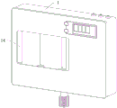
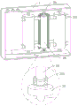
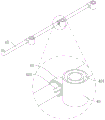
图1是本申请整体示意图。Fig. 1 is the overall schematic diagram of the present application.
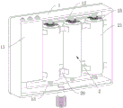
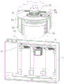
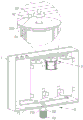
图2是过滤清理装置整体部件分布图(从后向前看)。Fig. 2 is a distribution diagram of the overall components of the filter cleaning device (viewed from the back).
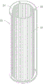
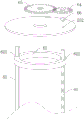
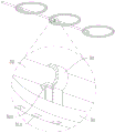
图3是清洁筒和通孔管罩剖视图。Fig. 3 is a sectional view of the cleaning cartridge and the through-hole pipe cover.
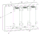
图4是过滤清理装置部分部件示意图。Fig. 4 is a schematic diagram of some components of the filter cleaning device.
图5是过滤清理装置部分部件剖视图。Fig. 5 is a cross-sectional view of some components of the filter cleaning device.
图6是离心清洁机构剖视图。Fig. 6 is a sectional view of the centrifugal cleaning mechanism.
图7是侧壁清洁组件爆炸图。Figure 7 is an exploded view of the sidewall cleaning assembly.
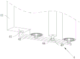
图8是内部清理机构示意图(从下往上看)。Figure 8 is a schematic diagram of the internal cleaning mechanism (viewed from bottom to top).
图9是内部清理机构部分部件剖视图。Fig. 9 is a cross-sectional view of some components of the internal cleaning mechanism.
图10是环区清洁机构剖视图。Fig. 10 is a cross-sectional view of the ring area cleaning mechanism.
图11是环区清洁机构部分部件剖视图(从下往上看)。Fig. 11 is a cross-sectional view of some parts of the ring area cleaning mechanism (viewed from bottom to top).
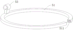
图12是刮除清洁环剖视图(出液环口倾斜示意图)。Fig. 12 is a sectional view of the scraper cleaning ring (a schematic diagram of the inclination of the liquid outlet ring).
附图标记说明:1、机体;11、驱动控制盒;12、送水管;13、回流管;2、过滤清理装置;20、间隔块;21、清洁筒;22、矩形块;23、通孔管罩;24、间隙环区;25、圆盖板;26、送水阀;27、回流阀;28、滤芯;3、离心清洁机构;4、内部清理机构;5、环区清洁机构;29、中心管;271、限位转槽;251、伸出孔;31、小型电机;32、蜗杆;33、蜗轮;6、侧壁清洁组件;61、方形限位杆;62、刮除清洁环;63、双向丝杆;64、小型齿轮;65、中型齿轮;621、方形贯穿孔;66、凸形圆柱;252、贯穿圆孔;622、螺纹穿孔;41、小型气泵;42、供气管;43、环槽圆柱;431、环形凹槽;44、哨形块;421、供气孔;51、出液环;52、供液管;7、排污组件;511、出液环口;53、弧形插管;521、供液孔;253、插管孔;71、倾斜引导板;72、塑料硬管;73、伸缩软管;711、排污孔;14、亚克力透明板。Explanation of reference signs: 1. Body; 11. Drive control box; 12. Water supply pipe; 13. Return pipe; 2. Filtration and cleaning device; 20. Interval block; 21. Cleaning cylinder; Pipe cover; 24. Gap ring area; 25. Round cover plate; 26. Water delivery valve; 27. Return valve; 28. Filter element; 3. Centrifugal cleaning mechanism; 4. Internal cleaning mechanism; 5. Ring area cleaning mechanism; 29. Center tube; 271, limit turn slot; 251, protruding hole; 31, small motor; 32, worm; 33, worm wheel; 6, side wall cleaning component; 61, square limit rod; 62, scrape cleaning ring; 63, two-way screw rod; 64, small gear; 65, medium gear; 621, square through hole; 66, convex cylinder; 252, through round hole; 622, threaded hole; 41, small air pump; 42, air supply pipe; 43 , ring groove cylinder; 431, ring groove; 44, whistle block; 421, air supply hole; 51, liquid outlet ring; 52, liquid supply pipe; 7, sewage assembly; 511, liquid outlet ring mouth; 53, arc Intubation; 521, liquid supply hole; 253, intubation hole; 71, inclined guide plate; 72, plastic hard tube; 73, telescopic hose; 711, sewage hole; 14, acrylic transparent plate.
具体实施方式Detailed ways
以下结合附图1-12对本申请作进一步详细说明。The present application will be described in further detail below in conjunction with accompanying drawings 1-12.
本申请实施例公开一种净水器,可以对净水器中的滤芯进行多方式有效的清理,并且在对滤芯进行清理时,不会对水质造成二次污染影响正常的用水安全;本申请提供一种净水器,包括机体1以及设置在机体1内的驱动控制盒11,驱动控制盒11两侧分别安装有送水管12和回流管13,需要说明的是,驱动控制盒11为现代净水器中的现有技术,驱动控制盒11中集成有电路控制线路板等,可以控制送水管12和回流管13的开启和关闭以及其他驱动部件的运作和停止;因是现有技术,驱动控制盒11内部详细结构未在图中示出;机体1内位于送水管12和回流管13之间设置有过滤清理装置2;将净水器与家中水管连接,送水管12可以向过滤清理装置2中供入自来水,过滤清理装置2将自来水过滤后通过回流管13将过滤后的水送出以供使用;而经过长时间的过滤使用后,用于过滤自来水的过滤部件上会附着堆积有大量杂质,需要及时清理,过滤清理装置2可以自动对过滤部件进行多方式有效清洁,并且在清洁时不会造成二次污染影响正常使用和用水安全。The embodiment of the present application discloses a water purifier, which can effectively clean the filter element in the water purifier in multiple ways, and when cleaning the filter element, it will not cause secondary pollution to the water quality and affect the normal water safety; the present application A water purifier is provided, including a
参照图1至图3所示,本实施例中优选为过滤清理装置2包括通过八个间隔块20等距固定安装在机体1内的三个清洁筒21,每个清洁筒21内通过八个矩形块22固定安装有通孔管罩23,并且在通孔管罩23上开设有多个过滤孔;清洁筒21和通孔管罩23之间形成间隙环区24,清洁筒21上侧固定盖合有圆盖板25;三个清洁筒21均处于送水管12和回流管13之间。Referring to Fig. 1 to Fig. 3, in the present embodiment, it is preferable that the
参照图4和图5所示,为了可以对家中自来水进行过滤,并对过滤部件进行多方式有效清洁,保障正常使用和用水安全,过滤清理装置2还包括送水阀26、回流阀27、滤芯28、离心清洁机构3、内部清理机构4以及环区清洁机构5;本实施例优选为三个送水阀26和三个回流阀27等距连通设置在送水管12和回流管13上,优选为三个滤芯28通过三个中心管29分别转动连通安装在三组送水阀26和回流阀27之间,即上下对称的一个送水阀26和一个回流阀27为一组,并处于清洁筒21通孔管罩23中,中心管29的上下两端分别密封转动安装在送水阀26和回流阀27上,而滤芯28则是处于清洁筒21通孔管罩23中,由于滤芯28和滤芯28中的中心管29为现有公知技术,即不再做过多说明,起到的作用是,自来水通过送水管12和送水阀26进入到各个中心管29和滤芯28中,通过滤芯28可以将自来水进行过滤,过滤之后的水通过回流阀27和回流管13送出,因此为现有技术,故中心管29和滤芯28的内部详细结构未在图中示出。Referring to Fig. 4 and Fig. 5, in order to filter the tap water at home and effectively clean the filter parts in multiple ways to ensure normal use and water safety, the
送水阀26和回流阀27上均开设有供中心管29密封转动的限位转槽271,圆盖板25上贯穿开设有供中心管29与送水阀26连通安装的伸出孔251,离心清洁机构3和内部清理机构4分别设于清洁筒21上侧和下侧,环区清洁机构5安装在圆盖板25上。经过一段时间使用后,滤芯28上会附着堆积有大量水中过滤的杂质,如不及时对滤芯28进行清理则会影响正常过滤使用和用水安全;具体的通过离心清洁机构3可以驱动中心管29和滤芯28旋转利用离心力对滤芯28上的一部分杂质进行清理,而处于滤芯28内部的杂质可以通过内部清理机构4进行清理,最后因利用离心力被清理甩掉的杂质一部分会被通孔管罩23阻挡,而另一部分体积更小不易附着在通孔管罩23侧壁上的杂质可以经过通孔管罩23上多个过滤孔进入清洁筒21和通孔管罩23之间的间隙环区24中,以防止这类体积较小的杂质在反弹力的作用下再次回到滤芯28上;针对这类杂质可以通过环区清洁机构5持续向间隙环区24中喷洒清洁液体在间隙环区24中形成柱状水帘,利用清洁液体形成的柱状水帘以对这类杂质进行清理。以实现对滤芯28进行多方式有效清洁。Both the
参照图6所示,由于需要对一部分附着在滤芯28上的杂质进行清理,离心清洁机构3包括小型电机31、蜗杆32、蜗轮33以及侧壁清洁组件6;小型电机31设置在驱动控制盒11上,蜗杆32固定安装在小型电机31转动端,蜗轮33固定套设在圆盖板25上方的中心管29上并与蜗杆32相啮合,启动小型电机31运作在蜗杆32的作用下可以驱动蜗轮33转动,由于蜗轮33与中心管29之间是固定连接的,即可以驱动中心管29和滤芯28旋转,在旋转离心力的作用下附着在滤芯28上的一部分杂质会被清理;侧壁清洁组件6设于圆盖板25和通孔管罩23中,与此同时会有部分体积较大的已经聚拢成团的杂质被甩出会附着在通孔管罩23侧壁上,而通过侧壁清洁组件6不仅可以对通孔管罩23侧壁上的附着物进行清理还可以对滤芯28表面起到刮除效果,以同时达到清洁滤芯28表面杂质的效果。With reference to shown in Figure 6, owing to need to clean up the impurity that a part is attached on the filter core 28, centrifugal cleaning mechanism 3 comprises small-sized motor 31, worm screw 32, worm wheel 33 and side wall cleaning assembly 6; Small-sized motor 31 is arranged on drive control box 11 Above, the worm 32 is fixedly mounted on the rotating end of the small motor 31, the worm gear 33 is fixedly sleeved on the central tube 29 above the round cover plate 25 and meshed with the worm 32, and the small motor 31 can be started to drive the worm gear under the action of the worm 32 33 rotation, because the worm wheel 33 and the central tube 29 are fixedly connected, that is, the central tube 29 and the filter core 28 can be driven to rotate, and a part of impurities attached to the filter core 28 will be cleaned under the action of the rotating centrifugal force; the side wall cleaning assembly 6 is located in the round cover plate 25 and the through-hole pipe cover 23, at the same time, some of the larger impurities that have gathered into agglomerates will be thrown out and will adhere to the side wall of the through-hole pipe cover 23, and pass through the side wall The cleaning assembly 6 can not only clean up the attachments on the side wall of the through-hole pipe cover 23 but also scrape the surface of the filter core 28 to achieve the effect of cleaning the surface impurities of the filter core 28 at the same time.
参照图6和图7所示,为了可以对通孔管罩23侧壁以及滤芯28表面同时进行清理,侧壁清洁组件6包括方形限位杆61、刮除清洁环62、双向丝杆63、小型齿轮64以及中型齿轮65;方形限位杆61固定安装在圆盖板25下侧,刮除清洁环62限位滑动设置在方形限位杆61上,并处于通孔管罩23和滤芯28之间,刮除清洁环62上贯穿开设有与方形限位杆61适配的方形贯穿孔621,双向丝杆63一端通过凸形圆柱66限位转动安装在圆盖板25上,另一端贯穿刮除清洁环62向下延伸,圆盖板25上贯穿开设有供凸形圆柱66安装的贯穿圆孔252,刮除清洁环62上螺纹贯穿开设有与双向丝杆63适配并供其穿透的螺纹穿孔622。6 and 7, in order to simultaneously clean the side wall of the through-
由于凸形圆柱66和双向丝杆63之间是固定连接设置,当凸形圆柱66受力发生转动时,双向丝杆63同步转动在与刮除清洁环62上的螺纹穿孔622配合下可以驱动刮除清洁环62在通孔管罩23和滤芯28之间上下往复滑动,进而可以对滤芯28表面和通孔管罩23侧壁起到刮除清洁的效果;小型齿轮64固定套设在处于圆盖板25上方的凸形圆柱66上,中型齿轮65固定套设在蜗轮33和圆盖板25之间的中心管29上并与小型齿轮64相啮合,小型电机31通过蜗轮33蜗杆32驱动中心管29旋转时,通过中型齿轮65和小型齿轮64可以同步驱动凸形圆柱66转动,即可以驱动双向丝杆63转动对刮除清洁环62形成驱动力,以实现小型电机31驱动中心管29和滤芯28旋转的同时,刮除清洁环62在滤芯28和通孔管罩23之间上下往复滑动以对滤芯28表面以及通孔管罩23侧壁进行清理。Since the
参照图8和图9所示,由于在滤芯28的内部同样附着堆积有大量水中过滤的杂质,这部分杂质同样需要被清理以确保滤芯28可以正常使用,内部清理机构4包括小型气泵41、供气管42以及环槽圆柱43;小型气泵41安装在驱动控制盒11上,供气管42连通设置在小型气泵41上,并且供气管42处于三个清洁筒21下方;环槽圆柱43转动套设在回流阀27和滤芯28之间的中心管29上,需要说明的是环槽圆柱43的长度刚好适配安装在回流阀27和滤芯28之间,即环槽圆柱43的上侧与滤芯28下侧抵触;环槽圆柱43上开设有环形凹槽431,环形凹槽431开口朝向并抵触在滤芯28下侧;环槽圆柱43和供气管42之间通过哨形块44连通设置,供气管42上开设有与哨形块44和环形凹槽431连通的供气孔421。小型气泵41启动可以通过供气管42和哨形块44向环槽圆柱43环形凹槽431中持续供入气体,气体通过环形凹槽431开口排至滤芯28内部,利用气体的注入将附着在滤芯28内部的杂质排出以达到清洁滤芯28内部杂质的目的,配合滤芯28旋转离心力和刮除清洁环62的刮除清理以进一步加强对滤芯28的清洁效果。With reference to Fig. 8 and shown in Fig. 9, because the impurity that a large amount of water filter is also attached and piled up in the inside of filter element 28, this part impurity also needs to be cleaned to ensure that filter element 28 can be used normally, internal cleaning mechanism 4 includes small air pump 41, supply The air pipe 42 and the ring groove cylinder 43; the small air pump 41 is installed on the drive control box 11, the air supply pipe 42 is communicated with and arranged on the small air pump 41, and the air supply pipe 42 is under the three cleaning cylinders 21; the ring groove cylinder 43 is rotated and sleeved on the On the central pipe 29 between the return valve 27 and the filter element 28, it should be noted that the length of the ring groove cylinder 43 is just suitable for installation between the return valve 27 and the filter element 28, that is, the upper side of the ring groove cylinder 43 and the bottom of the filter element 28 side conflict; the ring groove cylinder 43 is provided with an annular groove 431, and the opening of the ring groove 431 faces and interferes with the lower side of the filter element 28; the ring groove cylinder 43 and the air supply pipe 42 are communicated with each other through a whistle block 44, and the air supply pipe 42 An air supply hole 421 communicating with the whistle block 44 and the annular groove 431 is opened thereon. The
参照图10至图12所示,为了可以针对进入清洁筒21和通孔管罩23之间的间隙环区24中的杂质进行清理,环区清洁机构5包括出液环51、供液管52以及排污组件7;出液环51固定安装在圆盖板25下侧,并处于间隙环区24上方,出液环51上开设有多个出液环口511,出液环口511为倾斜开口朝向清洁筒21内侧壁设置,出液环口511倾斜设置的目的是为了清洁液体可以通过出液环口511倾斜流出出液环51而排至清洁筒21内侧壁上;供液管52安装在驱动控制盒11上,且处于圆盖板25上方,出液环51和供液管52之间通过弧形插管53连通设置,供液管52上开设有与弧形插管53和出液环口511连通的供液孔521,将净水器安装好与家中管道连接后,驱动控制盒11可以控制供液管52的开启和关闭,以在需要的时候将自来水或者清洁液体通过供液管52和弧形插管53注入出液环51中,再通过出液环口511将液体排向清洁筒21内侧壁上以形成柱状水帘持续对清洁筒21内壁进行冲刷。Referring to Figures 10 to 12, in order to clean up the impurities entering the
进而实现对进入清洁筒21和通孔管罩23之间的杂质进行清理,需要说明的是,柱状水帘不会充满整个间隙环区24,由于出液环口511开设的位置关系只会在靠近清洁筒21内侧壁的位置处形成柱状水帘,使得用于清洁的液体不会通过通孔管罩23上的过滤孔进入滤芯28中;圆盖板25上贯穿开设有供弧形插管53安装的插管孔253,排污组件7设于机体1下侧,被清理的杂质以及用于清洁的液体可以通过排污组件7排出机体1。Furthermore, the impurities entering between the cleaning
回看图10所示,由于需要将清理后的杂质和清洁液体排出机体1,排污组件7包括倾斜引导板71、塑料硬管72以及伸缩软管73;倾斜引导板71对称可拆卸安装在机体1内底壁上,滤芯28表面和通孔管罩23内侧壁上被刮除的杂质以及对间隙环区24进行清理的清洁液体可以通过清洁筒21下端排出至倾斜引导板71上;塑料硬管72固定安装在机体1下侧,机体1和倾斜引导板71上均开设有与塑料硬管72连通的排污孔711,在倾斜引导板71倾斜面的作用下可以引导杂质和清洁液体向排污孔711中流动排出;伸缩软管73固定安装在塑料硬管72下侧,伸缩软管73的另一端可以与家中的排污管道连接。Looking back at Figure 10, since the cleaned impurities and cleaning liquid need to be discharged from the
为防止倾斜引导板71在长时间的使用下表面会附着堆积有污渍,影响机体1内部环境,可以在倾斜引导板71使用一段时间后进行更换以确保机体1内部环境的洁净。In order to prevent the inclined guide plate 71 from attaching and accumulating dirt on the lower surface of the long-term use and affecting the internal environment of the
回看图1所示,机体1外侧壁上还固定安装有便于观察机体1内部的亚克力透明板14,在需要观察了解清洁情况时,可以通过亚克力透明板14清楚的观察到机体1内部排污情况。Looking back at Figure 1, the outer wall of the
本实施例的实施原理为:The implementation principle of this embodiment is:
(1)设置安装:首先对净水器进行安装使其与家中供水管道进行连接,其次将机体1下方的伸缩软管73的一端与家中的排污管道连接,之后便可以正常使用对家中的自来水进行过滤,自来水通过送水管12进入中心管29和滤芯28中进行过滤,过滤之后的水再通过回流管13流出以供日常使用。(1) Setting and installation: first, the water purifier is installed so that it is connected to the water supply pipe in the home, and secondly, one end of the
(2)滤芯清洁:机体1中的滤芯28使用了一段时间后容易堆积附着有大量水中过滤的杂质,便需要定期对滤芯28进行清洁以确保正常使用保障用水安全;对滤芯28进行清洁时,首先关闭送水管12停止向中心管29和滤芯28中供水,随后启动离心清洁机构3、内部清理机构4以及环区清洁机构5运作,离心清洁机构3可以通过驱动中心管29和滤芯28旋转利用离心力对一部分的杂质进行清理,而内部清理机构4可以对滤芯28内部附着的杂质进行清洁。(2) Filter element cleaning: After the
(3)内壁清洁:小型电机31启动驱动中心管29和滤芯28旋转的同时,侧壁清洁组件6同步运作使得刮除清洁环62在滤芯28和通孔管罩23之间上下往复滑动,以对滤芯28表面和通孔管罩23内侧壁进行刮除清理,针对清洁筒21和通孔管罩23之间间隙环区24的清理则通过环区清洁机构5完成,环区清洁机构5运作可以对清洁筒21内侧壁持续进行液体冲刷形成柱状水帘,从而达到对清洁筒21内侧壁清洁的目的。(3) Inner wall cleaning: when the
(4)污渍排出:滤芯28表面和通孔管罩23内侧壁上被刮除的杂质以及对间隙环区24进行清理的清洁液体可以通过清洁筒21下端排出至倾斜引导板71上,在倾斜引导板71倾斜面的作用下可以引导杂质和清洁液体向排污孔711中流动排出,最后伸缩软管73排至排污管道。(4) Dirt discharge: the impurities scraped off on the surface of the
本具体实施方式的实施例均为本发明的较佳实施例,并非依此限制本发明的保护范围,故:凡依本发明的结构、形状、原理所做的等效变化,均应涵盖于本发明的保护范围之内。The embodiments of this specific implementation mode are all preferred embodiments of the present invention, and are not intended to limit the protection scope of the present invention, so: all equivalent changes made according to the structure, shape and principle of the present invention should be covered by within the protection scope of the present invention.
Claims (8)
Priority Applications (1)
| Application Number | Priority Date | Filing Date | Title |
|---|---|---|---|
| CN202310398977.2A CN116099261B (en) | 2023-04-14 | 2023-04-14 | Water purifier |
Applications Claiming Priority (1)
| Application Number | Priority Date | Filing Date | Title |
|---|---|---|---|
| CN202310398977.2A CN116099261B (en) | 2023-04-14 | 2023-04-14 | Water purifier |
Publications (2)
| Publication Number | Publication Date |
|---|---|
| CN116099261A true CN116099261A (en) | 2023-05-12 |
| CN116099261B CN116099261B (en) | 2023-06-16 |
Family
ID=86267678
Family Applications (1)
| Application Number | Title | Priority Date | Filing Date |
|---|---|---|---|
| CN202310398977.2A Active CN116099261B (en) | 2023-04-14 | 2023-04-14 | Water purifier |
Country Status (1)
| Country | Link |
|---|---|
| CN (1) | CN116099261B (en) |
Cited By (1)
| Publication number | Priority date | Publication date | Assignee | Title |
|---|---|---|---|---|
| CN116986677A (en) * | 2023-09-26 | 2023-11-03 | 山东宏科水电设备有限公司 | Sewage treatment equipment based on ultralow-pressure nanofiltration membrane |
Citations (9)
| Publication number | Priority date | Publication date | Assignee | Title |
|---|---|---|---|---|
| CN2289784Y (en) * | 1996-08-09 | 1998-09-02 | 郑祥康 | Semi-automatic dirt eliminating purifier |
| WO2008065313A2 (en) * | 2006-12-01 | 2008-06-05 | WINDDROP, Société à responsabilité limitée | Vacuum suction and cleaning apparatus |
| CN201823371U (en) * | 2010-09-01 | 2011-05-11 | 方志杰 | Water purifier |
| DE102016112112A1 (en) * | 2015-07-03 | 2017-01-05 | Seven Juice Co., Ltd. | Centrifugal filter device and method for operating the same |
| CN108261828A (en) * | 2016-12-30 | 2018-07-10 | 福州品行科技发展有限公司 | A kind of rotary-cleaning filter core water purifier |
| JP3226481U (en) * | 2019-03-25 | 2020-07-02 | ▲い▼智 林 | Water filtration equipment |
| CN211635446U (en) * | 2019-11-15 | 2020-10-09 | 杭州智果科技有限公司 | Cleaning device applied to water purifier |
| CN214913842U (en) * | 2021-01-27 | 2021-11-30 | 安徽乐美达生物科技有限公司 | A kind of cosmetic manufacturing water deep activation treatment device |
| CN215388084U (en) * | 2021-08-11 | 2022-01-04 | 合肥珝润生物科技有限公司 | Oil residue separation processing apparatus is used in chemical industry grease production |
-
2023
- 2023-04-14 CN CN202310398977.2A patent/CN116099261B/en active Active
Patent Citations (9)
| Publication number | Priority date | Publication date | Assignee | Title |
|---|---|---|---|---|
| CN2289784Y (en) * | 1996-08-09 | 1998-09-02 | 郑祥康 | Semi-automatic dirt eliminating purifier |
| WO2008065313A2 (en) * | 2006-12-01 | 2008-06-05 | WINDDROP, Société à responsabilité limitée | Vacuum suction and cleaning apparatus |
| CN201823371U (en) * | 2010-09-01 | 2011-05-11 | 方志杰 | Water purifier |
| DE102016112112A1 (en) * | 2015-07-03 | 2017-01-05 | Seven Juice Co., Ltd. | Centrifugal filter device and method for operating the same |
| CN108261828A (en) * | 2016-12-30 | 2018-07-10 | 福州品行科技发展有限公司 | A kind of rotary-cleaning filter core water purifier |
| JP3226481U (en) * | 2019-03-25 | 2020-07-02 | ▲い▼智 林 | Water filtration equipment |
| CN211635446U (en) * | 2019-11-15 | 2020-10-09 | 杭州智果科技有限公司 | Cleaning device applied to water purifier |
| CN214913842U (en) * | 2021-01-27 | 2021-11-30 | 安徽乐美达生物科技有限公司 | A kind of cosmetic manufacturing water deep activation treatment device |
| CN215388084U (en) * | 2021-08-11 | 2022-01-04 | 合肥珝润生物科技有限公司 | Oil residue separation processing apparatus is used in chemical industry grease production |
Cited By (2)
| Publication number | Priority date | Publication date | Assignee | Title |
|---|---|---|---|---|
| CN116986677A (en) * | 2023-09-26 | 2023-11-03 | 山东宏科水电设备有限公司 | Sewage treatment equipment based on ultralow-pressure nanofiltration membrane |
| CN116986677B (en) * | 2023-09-26 | 2023-12-15 | 山东宏科水电设备有限公司 | Sewage treatment equipment based on ultralow-pressure nanofiltration membrane |
Also Published As
| Publication number | Publication date |
|---|---|
| CN116099261B (en) | 2023-06-16 |
Similar Documents
| Publication | Publication Date | Title |
|---|---|---|
| CN201337844Y (en) | Automatic brush type cleaning self-absorption filter | |
| CN108126396A (en) | Suction type self-cleaning filter | |
| CN109107249A (en) | It is a kind of can automatic cleaning filter core filter and its working method | |
| CN116099261B (en) | Water purifier | |
| CN208049509U (en) | Suction type self-cleaning filter | |
| CN101822918B (en) | Multipath sewage filtering apparatus | |
| CN104857760A (en) | Full-automatic self-cleaning filter | |
| CN116651042A (en) | Self-cleaning filter | |
| CN205516741U (en) | Backwash filter | |
| CN209475743U (en) | A kind of purified water preparation multilayer fine filtering device | |
| CN219897244U (en) | Self-cleaning filter device | |
| CN206103469U (en) | Backwashing filter | |
| CN116726558A (en) | A filter cartridge device with an anti-clogging structure | |
| CN202398158U (en) | Filter provided with self-cleaning and back-cleaning material leakage prevention device | |
| CN211523370U (en) | Multi-cavity intelligent non-negative pressure water supply equipment | |
| CN2765654Y (en) | Differential pressure backwashing filter | |
| CN211411178U (en) | Self-cleaning filter | |
| CN208266990U (en) | A kind of backwash water tank | |
| CN114162484A (en) | Drainage device for spring type floating roof storage tank | |
| CN120054077B (en) | But deep purification's commercial water purifier | |
| CN112076520A (en) | Combined self-cleaning seawater filter | |
| CN207886794U (en) | A kind of Microfilter | |
| CN217092362U (en) | Full-automatic self-cleaning filter with anti-blocking structure | |
| CN218076665U (en) | A kind of vacuum filter for waterproof nano-coating processing | |
| CN206444288U (en) | A self-cleaning duplex filter |
Legal Events
| Date | Code | Title | Description |
|---|---|---|---|
| PB01 | Publication | ||
| PB01 | Publication | ||
| SE01 | Entry into force of request for substantive examination | ||
| SE01 | Entry into force of request for substantive examination | ||
| GR01 | Patent grant | ||
| GR01 | Patent grant | ||
| TR01 | Transfer of patent right |
Effective date of registration: 20250929 Address after: 410000 Hunan Province, Changsha City, Furong District, No. 725 Yuanda Second Road, Huiyicheng Community, Building 10, Room 204 Patentee after: Zhou Shuangbiao Country or region after: China Address before: 410000 Hunan Province, Changsha City, Furong District, Xianghu Street, Nanhu Community, Sanxiang Nanhu Large Market Auto Parts City Supplies Area, Building 6, Room 6207 Patentee before: HUNAN LEMISITE ENVIRONMENTAL PROTECTION TECHNOLOGY Co.,Ltd. Country or region before: China |
|
| TR01 | Transfer of patent right | ||
| TR01 | Transfer of patent right |
Effective date of registration: 20251209 Address after: 410001 Hunan Province, Changsha City, Furong District, Xianghu Street, Nanhu Community, Sanxiang Nanhu Large Market, Auto Parts City Supplies Area, Building 6, Room 6207 Patentee after: HUNAN LEMISITE ENVIRONMENTAL PROTECTION TECHNOLOGY Co.,Ltd. Country or region after: China Address before: 410000 Hunan Province, Changsha City, Furong District, No. 725 Yuanda Second Road, Huiyicheng Community, Building 10, Room 204 Patentee before: Zhou Shuangbiao Country or region before: China |
|
| TR01 | Transfer of patent right |