CN116081790A - Sewage treatment device - Google Patents
Sewage treatment device Download PDFInfo
- Publication number
- CN116081790A CN116081790A CN202310192930.0A CN202310192930A CN116081790A CN 116081790 A CN116081790 A CN 116081790A CN 202310192930 A CN202310192930 A CN 202310192930A CN 116081790 A CN116081790 A CN 116081790A
- Authority
- CN
- China
- Prior art keywords
- water
- reaction barrel
- reaction
- barrel body
- sewage treatment
- Prior art date
- Legal status (The legal status is an assumption and is not a legal conclusion. Google has not performed a legal analysis and makes no representation as to the accuracy of the status listed.)
- Pending
Links
Images
Classifications
-
- C—CHEMISTRY; METALLURGY
- C02—TREATMENT OF WATER, WASTE WATER, SEWAGE, OR SLUDGE
- C02F—TREATMENT OF WATER, WASTE WATER, SEWAGE, OR SLUDGE
- C02F9/00—Multistage treatment of water, waste water or sewage
-
- B—PERFORMING OPERATIONS; TRANSPORTING
- B01—PHYSICAL OR CHEMICAL PROCESSES OR APPARATUS IN GENERAL
- B01F—MIXING, e.g. DISSOLVING, EMULSIFYING OR DISPERSING
- B01F31/00—Mixers with shaking, oscillating, or vibrating mechanisms
- B01F31/40—Mixers with shaking, oscillating, or vibrating mechanisms with an axially oscillating rotary stirrer
-
- B—PERFORMING OPERATIONS; TRANSPORTING
- B01—PHYSICAL OR CHEMICAL PROCESSES OR APPARATUS IN GENERAL
- B01F—MIXING, e.g. DISSOLVING, EMULSIFYING OR DISPERSING
- B01F35/00—Accessories for mixers; Auxiliary operations or auxiliary devices; Parts or details of general application
- B01F35/10—Maintenance of mixers
- B01F35/12—Maintenance of mixers using mechanical means
- B01F35/123—Maintenance of mixers using mechanical means using scrapers for cleaning mixers
-
- C—CHEMISTRY; METALLURGY
- C02—TREATMENT OF WATER, WASTE WATER, SEWAGE, OR SLUDGE
- C02F—TREATMENT OF WATER, WASTE WATER, SEWAGE, OR SLUDGE
- C02F1/00—Treatment of water, waste water, or sewage
- C02F1/001—Processes for the treatment of water whereby the filtration technique is of importance
-
- C—CHEMISTRY; METALLURGY
- C02—TREATMENT OF WATER, WASTE WATER, SEWAGE, OR SLUDGE
- C02F—TREATMENT OF WATER, WASTE WATER, SEWAGE, OR SLUDGE
- C02F1/00—Treatment of water, waste water, or sewage
- C02F1/28—Treatment of water, waste water, or sewage by sorption
-
- C—CHEMISTRY; METALLURGY
- C02—TREATMENT OF WATER, WASTE WATER, SEWAGE, OR SLUDGE
- C02F—TREATMENT OF WATER, WASTE WATER, SEWAGE, OR SLUDGE
- C02F1/00—Treatment of water, waste water, or sewage
- C02F1/52—Treatment of water, waste water, or sewage by flocculation or precipitation of suspended impurities
- C02F1/5281—Installations for water purification using chemical agents
-
- B—PERFORMING OPERATIONS; TRANSPORTING
- B01—PHYSICAL OR CHEMICAL PROCESSES OR APPARATUS IN GENERAL
- B01F—MIXING, e.g. DISSOLVING, EMULSIFYING OR DISPERSING
- B01F2101/00—Mixing characterised by the nature of the mixed materials or by the application field
- B01F2101/305—Treatment of water, waste water or sewage
-
- C—CHEMISTRY; METALLURGY
- C02—TREATMENT OF WATER, WASTE WATER, SEWAGE, OR SLUDGE
- C02F—TREATMENT OF WATER, WASTE WATER, SEWAGE, OR SLUDGE
- C02F2303/00—Specific treatment goals
- C02F2303/14—Maintenance of water treatment installations
-
- Y—GENERAL TAGGING OF NEW TECHNOLOGICAL DEVELOPMENTS; GENERAL TAGGING OF CROSS-SECTIONAL TECHNOLOGIES SPANNING OVER SEVERAL SECTIONS OF THE IPC; TECHNICAL SUBJECTS COVERED BY FORMER USPC CROSS-REFERENCE ART COLLECTIONS [XRACs] AND DIGESTS
- Y02—TECHNOLOGIES OR APPLICATIONS FOR MITIGATION OR ADAPTATION AGAINST CLIMATE CHANGE
- Y02W—CLIMATE CHANGE MITIGATION TECHNOLOGIES RELATED TO WASTEWATER TREATMENT OR WASTE MANAGEMENT
- Y02W10/00—Technologies for wastewater treatment
- Y02W10/10—Biological treatment of water, waste water, or sewage
Landscapes
- Chemical & Material Sciences (AREA)
- Engineering & Computer Science (AREA)
- Life Sciences & Earth Sciences (AREA)
- Hydrology & Water Resources (AREA)
- Environmental & Geological Engineering (AREA)
- Water Supply & Treatment (AREA)
- Organic Chemistry (AREA)
- Chemical Kinetics & Catalysis (AREA)
- Mechanical Engineering (AREA)
- General Chemical & Material Sciences (AREA)
- Separation Of Suspended Particles By Flocculating Agents (AREA)
Abstract
Description
技术领域technical field
本发明涉及污水处理技术领域,特别涉及一种污水处理装置。The invention relates to the technical field of sewage treatment, in particular to a sewage treatment device.
背景技术Background technique
污水处理是为使污水达到排入某一水体或再次使用的水质要求对其进行净化的过程,被广泛应用于建筑、农业、交通、能源、石化、环保、城市景观、医疗、餐饮等各个领域,污水的正确处理能确保城市居民的用水安全问题,也避免了污水对城市形象及外观环境影响和危害,在一定程度上遏制了对城市的污染问题,起到保护环境的作用,有利于促进城市的发展。Sewage treatment is the process of purifying sewage to meet the water quality requirements of being discharged into a certain water body or reused. It is widely used in various fields such as construction, agriculture, transportation, energy, petrochemical, environmental protection, urban landscape, medical treatment, and catering. , the correct treatment of sewage can ensure the safety of water for urban residents, and also avoid the impact and harm of sewage on the city's image and appearance environment. city development.
在污水处理的过程中需要使用污水处理装置对污水进行处理,通过向反应桶内添加沉淀剂将污水中的可沉淀杂质沉淀分解出来,分解出来的沉淀杂质具有一定的粘附性容易附着在反应桶内壁,日积月累在反应桶内形成厚厚污垢层,而反应桶在组装后是不方便拆卸的,对其内部的污垢没办法人工干预清理。In the process of sewage treatment, it is necessary to use a sewage treatment device to treat the sewage. By adding a precipitant to the reaction tank, the precipitated impurities in the sewage can be precipitated and decomposed. The decomposed precipitated impurities have certain adhesion and are easy to attach to the reaction tank. The inner wall of the barrel has accumulated a thick layer of dirt in the reaction barrel over time, and the reaction barrel is inconvenient to disassemble after assembly, and there is no way to manually clean up the dirt inside.
为了解决上述问题,便于反应桶内壁的自动清理,本案由此产生。In order to solve the above problems and facilitate the automatic cleaning of the inner wall of the reaction barrel, this case arose.
发明内容Contents of the invention
因此,针对上述的问题,本发明提出一种结构设计合理、操作简易、能实现自动清理反应桶内壁的一种污水处理装置。Therefore, in view of the above problems, the present invention proposes a sewage treatment device with reasonable structural design, simple operation, and automatic cleaning of the inner wall of the reaction tank.
为解决上述技术问题,本发明采取的解决方案为:一种污水处理装置,包括水平放置的反应桶本体、用于支撑反应桶本体的支座,所述反应桶本体一侧上开设有供水体进入的进水口、上端开设有用于投放沉淀药剂的投放口、下端开设有供水体流出的出水口,所述出水口上设置有用于控制水体排放的控制阀,所述反应桶本体前端开设有端口,所述端口内设置有用于密封端口的端盖,所述反应桶本体内部设置有至少一个的用于刮除反应桶内壁附着的水垢的刮板,所述端盖上设置有用于驱动所述刮板沿所述反应桶内壁转动将附着在内壁上的水垢刮除的第一驱动机构,所述反应桶本体内设置有用于搅拌沉淀药剂使其与水体充分混合加快沉淀反应速度、用于使水体保持流动状态避免沉淀物附着便于将沉淀物沿出水口排出的搅拌机构,所述进水口上设置有用于在水体进入反应桶本体内部前先去除水体中杂质的预处理机构,所述出水口上设置有用于对沉淀后的沉淀物进行过滤的过滤机构,所述反应桶本体内壁上设置有用于反馈反应桶本体内壁的水垢附着情况判断是否需要人工清洗的反馈机构。In order to solve the above-mentioned technical problems, the solution adopted by the present invention is: a sewage treatment device, comprising a horizontally placed reaction barrel body, a support for supporting the reaction barrel body, and a water supply body is provided on one side of the reaction barrel body The upper end of the water inlet is provided with a drop-in port for injecting precipitation agents, and the lower end is provided with a water outlet for the water body to flow out. The water outlet is provided with a control valve for controlling the discharge of the water body, and the front end of the reaction barrel body is provided with a port. , the port is provided with an end cover for sealing the port, and at least one scraper for scraping the scale attached to the inner wall of the reaction tank is provided inside the reaction barrel body, and the end cover is provided with a device for driving the The scraper rotates along the inner wall of the reaction tank to scrape off the scale attached to the inner wall. The reaction tank body is provided with a stirring precipitation agent to fully mix with the water body to speed up the precipitation reaction speed. The water body maintains a flowing state to avoid sediment adhesion and facilitates the sediment to be discharged along the water outlet. The water inlet is provided with a pretreatment mechanism for removing impurities in the water body before the water body enters the reaction tank body. The water outlet A filter mechanism for filtering the precipitated sediment is provided on the top, and a feedback mechanism for feedback of scale adhesion on the inner wall of the reaction barrel body is provided on the inner wall of the reaction barrel body to judge whether manual cleaning is required.
进一步改进的是:所述第一驱动机构包括转动盘,所述端盖上开设有转动开口,所述转动盘密封转动设置于所述转动开口内,所述刮板一端设置于所述转动盘上,所述反应桶上设置有用于驱动所述转动盘带动刮板转动刮除水垢的驱动装置。A further improvement is that: the first drive mechanism includes a rotating disk, a rotating opening is opened on the end cover, the rotating disk is arranged in the rotating opening in a sealed manner, and one end of the scraper is arranged on the rotating disk Above, the reaction barrel is provided with a driving device for driving the rotating disk to drive the scraper to rotate and scrape off scale.
进一步改进的是:所述驱动装置包括第一电机、传动齿轮、外齿环,所述外齿环可转动套设于所述反应桶本体外壁上,所述外齿环与所述转动盘之间设置有至少一根用于外齿环带动转动盘同步转动的同步杆,所述第一电机的壳体固定设置于所述反应桶本体上,所述传动齿轮固定套设于所述第一电机的旋转轴上,所述传动齿轮与所述外齿环啮合传动。A further improvement is that: the driving device includes a first motor, a transmission gear, and an external gear ring, the external gear ring is rotatably sleeved on the outer wall of the reaction barrel body, and the connection between the external gear ring and the rotating disk There is at least one synchronous rod used for the outer gear ring to drive the rotating disk to rotate synchronously. The housing of the first motor is fixed on the body of the reaction barrel, and the transmission gear is fixedly sleeved on the first On the rotating shaft of the motor, the transmission gear is engaged with the external gear ring for transmission.
进一步改进的是:所述搅拌机构包括沿反应桶本体轴向设置于反应桶内部的搅拌架,所述搅拌架一端密封可滑移转动设置于所述反应桶本体上远离所述端盖的一端上,所述反应桶本体上设置有驱动所述搅拌架转动搅拌沉淀药剂的转动驱动装置以及用于驱动搅拌架沿轴向滑移运动使搅拌架处于活动状态减少水垢附着在搅拌架上的滑移驱动装置。It is further improved that: the stirring mechanism includes a stirring frame arranged inside the reaction barrel along the axial direction of the reaction barrel body, and one end of the stirring frame is sealed and slidable and rotatably arranged on the end of the reaction barrel body away from the end cover Above, the reaction barrel body is provided with a rotating drive device that drives the stirring frame to rotate and stir the precipitation agent, and a rotating drive device for driving the stirring frame to slide along the axial direction so that the stirring frame is in an active state to reduce scale adhesion on the stirring frame. Move the drive unit.
进一步改进的是:所述转动驱动装置包括第二电机,所述搅拌架的一端密封可滑移转动穿出所述反应桶本体固定设置于所述第二电机的旋转轴上。A further improvement is that: the rotation driving device includes a second motor, and one end of the stirring frame is sealed and slidable and rotates through the reaction barrel body and is fixedly arranged on the rotating shaft of the second motor.
进一步改进的是:所述滑移驱动装置包括底座、滑移座,所述滑移座沿所述搅拌架轴向可往复滑移设置于底座上,所述第二电机的壳体固定设置于所述滑移座上,所述底座与滑移座之间设置有用于驱动所述滑移座往复滑移的滑移组件。A further improvement is: the sliding drive device includes a base and a sliding seat, the sliding seat is reciprocally slidable and arranged on the base along the axial direction of the stirring frame, and the housing of the second motor is fixed on the On the sliding seat, a sliding assembly for driving the sliding seat to reciprocate is arranged between the base and the sliding seat.
进一步改进的是:所述滑移组件包括L型摆动杆、连接杆,所述L型摆动杆下端部可转动设置于所述底座上,所述连接杆一端设置于所述滑移座上,另一端设置于所述L型摆动杆上端部,所述L型摆动杆下端部沿竖直轴向上开设有驱动槽,所述驱动槽内活动设置有L型驱动杆,所述底座上设置有用于驱动所述L型驱动杆偏心转动带动L型摆动杆往复摆动以带动搅拌架滑移的第三电机,所述第三电机的壳体固定设置于所述底座上个,所述L型驱动杆一端固定设置于所述第三电机的旋转轴上,另一端活动穿设于所述驱动槽内。A further improvement is: the sliding assembly includes an L-shaped swing rod and a connecting rod, the lower end of the L-shaped swing rod is rotatably arranged on the base, and one end of the connecting rod is arranged on the sliding seat, The other end is arranged on the upper end of the L-shaped swing rod, and the lower end of the L-shaped swing rod is provided with a drive slot along the vertical axis, and an L-shaped drive rod is movably arranged in the drive slot. There is a third motor for driving the L-shaped driving rod to rotate eccentrically to drive the L-shaped swing rod to swing back and forth to drive the stirring frame to slide. The housing of the third motor is fixed on the base, and the L-shaped One end of the driving rod is fixedly arranged on the rotating shaft of the third motor, and the other end is movably installed in the driving slot.
进一步改进的是:所述预处理机构包括预处理池,所述预处理池的进水端上开设有预处理进水口、出水端上开设有预处理出水口,所述出水口处设置有用于将水体泵入反应桶本体内部的第一水泵,所述第一水泵的进水端与所述预处理出水口相连接,所述第一水泵的出水端与所述进水口相连通,所述预处理池内分别可拆装设置有用于过滤污水的隔膜、位于所述隔膜的进水端设置的用于对絮状物进行阻隔的栅格、位于隔膜与栅格之间设置的用于吸附污水中的微粒杂质避免污水中的杂质堵塞隔膜影响过水的吸附支架,所述吸附支架上均匀分布有通过材料特性来主动吸附微粒杂质的吸附孔。It is further improved that: the pretreatment mechanism includes a pretreatment pool, the water inlet of the pretreatment pool is provided with a pretreatment water inlet, and the water outlet is provided with a pretreatment water outlet, and the water outlet is provided with a The water body is pumped into the first water pump inside the reaction barrel body, the water inlet end of the first water pump is connected with the water outlet of the pretreatment, the water outlet end of the first water pump is connected with the water inlet, the In the pretreatment tank, there are detachable membranes for filtering sewage, grids for blocking flocs at the water inlet of the membranes, and grids for absorbing sewage between the membranes and grids. The particulate impurity in the sewage prevents the impurity in the sewage from clogging the diaphragm and affecting the adsorption bracket of the water. The adsorption bracket is evenly distributed with adsorption holes that actively adsorb the particulate impurities through material characteristics.
进一步改进的是:所述过滤机构包括过滤池,所述过滤池与所述出水口之间设置有排水管,所述排水管一端固定连接于所述出水口,另一端可拆装卡合设置于所述过滤池上,所述过滤池内上端可拆装设置有用于对排水管排出的沉淀后的水体进行过滤的过滤网,所述过滤池下端部上开设有排水口,所述排水口上连接有用于将过滤池内的水体排出的第二水泵。A further improvement is: the filter mechanism includes a filter tank, a drain pipe is arranged between the filter tank and the water outlet, one end of the drain pipe is fixedly connected to the water outlet, and the other end is detachable and engaged On the filter tank, the upper end of the filter tank is detachably provided with a filter screen for filtering the settled water discharged from the drain pipe, and a drain port is opened on the lower end of the filter tank, and the drain port is connected with a useful The second water pump used to discharge the water body in the filter tank.
进一步改进的是:所述反馈机构包括T型滑槽、反馈片,所述T型滑槽位于所述投放口位置处沿周向开设于所述反应桶本体内壁上,所述T型滑槽上端口与所述投放口相连通,所述反馈片的形状与所述T型滑槽的形状相适应可滑移设置于所述T型滑槽内,所述反馈片的内表面与所述反应通本体内壁平齐,所述反馈片上端部开设有供工具勾住将反馈片拖拽出投放口外观察的拖拽孔。It is further improved that: the feedback mechanism includes a T-shaped chute and a feedback piece, the T-shaped chute is located at the position of the insertion port and is circumferentially opened on the inner wall of the reaction barrel body, and the T-shaped chute The upper port is connected with the insertion port, the shape of the feedback piece is adapted to the shape of the T-shaped chute and can be slidably arranged in the T-shaped chute, and the inner surface of the feedback piece is in contact with the shape of the T-shaped chute. The inner wall of the reaction channel body is flush, and the upper end of the feedback sheet is provided with a drag hole for tools to hook and drag the feedback sheet out of the feeding port for observation.
通过采用前述技术方案,本发明的有益效果是:By adopting the aforementioned technical scheme, the beneficial effects of the present invention are:
1、本案通过在反应桶本体内设置刮板来自动对反应桶内部刮除清洁,免除人工劳动力,刮板可随反应桶本体工作实时进行,有效保持反应桶本体内部的清洁,提高污水的处理质量。1. In this case, a scraper is installed in the reaction barrel to automatically scrape and clean the inside of the reaction barrel, eliminating the need for manual labor. The scraper can work in real time with the reaction barrel, effectively keeping the inside of the reaction barrel clean and improving the treatment of sewage quality.
2、污水先通过栅格和吸附支架,避免污水的絮状物和杂质附着在隔膜表面造成装置堵塞,从而提高了预处理机构的工作稳定性。2. The sewage first passes through the grid and the adsorption bracket to avoid the clogging of the device caused by the flocs and impurities of the sewage adhering to the surface of the diaphragm, thereby improving the working stability of the pretreatment mechanism.
3、转动滑移设置的搅拌架具有径向和轴向两个搅拌方向,扩大了搅拌架的有效作用范围,提高了沉淀药剂在污水中混合的均匀性,从而提高了污水的处理质量,同时轴向的滑移带动搅拌架的支干在往复运动过程中始终与水体相互作用,将支干上的污垢震荡下来。3. The stirring frame set by rotating and sliding has two stirring directions, radial and axial, which expands the effective range of the stirring frame and improves the mixing uniformity of the sedimentation agent in the sewage, thereby improving the quality of sewage treatment. The axial sliding drives the stem of the stirring frame to interact with the water body all the time during the reciprocating motion, shaking off the dirt on the stem.
4、相比将反应桶本体内的昏暗环境,将反馈片拖拽出反应桶本体10外部借助自然光线可以清楚的看见水垢的附着情况,且反馈为透明的可更直观的判断出是否需要清洁反应桶本体。4. Compared with the dark environment inside the reaction barrel body, drag the feedback sheet out of the
附图说明Description of drawings
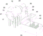
图1是本发明实施例一种污水处理装置的立体结构示意图。Fig. 1 is a schematic diagram of a three-dimensional structure of a sewage treatment device according to an embodiment of the present invention.
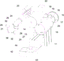
图2是本发明实施例一种污水处理装置的结构爆炸图。Fig. 2 is an exploded view of the structure of a sewage treatment device according to an embodiment of the present invention.
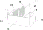
图3是本发明实施例一种污水处理装置中的预处理机构的结构示意图。Fig. 3 is a schematic structural diagram of a pretreatment mechanism in a sewage treatment device according to an embodiment of the present invention.
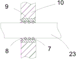
图4是本发明实施例一种污水处理装置中搅拌架与反应桶本体的安装结构示意图。Fig. 4 is a schematic diagram of the installation structure of a stirring frame and a reaction tank body in a sewage treatment device according to an embodiment of the present invention.
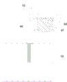
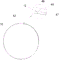
图5是本发明实施例一种污水处理装置中反馈机构的结构示意图。Fig. 5 is a structural schematic diagram of a feedback mechanism in a sewage treatment device according to an embodiment of the present invention.
图6是本发明实施例一种污水处理装置中反馈机构的剖视结构示意图。Fig. 6 is a schematic cross-sectional structure diagram of a feedback mechanism in a sewage treatment device according to an embodiment of the present invention.
实施方式Implementation
现结合附图和具体实施例对本发明进一步说明。The present invention will be further described in conjunction with the accompanying drawings and specific embodiments.
参考图1至图6,本发明实施例所揭示的是一种污水处理装置,包括水平放置的反应桶本体10、用于支撑反应桶本体10的支座11,所述反应桶本体10一侧上开设有供水体进入的进水口14、上端开设有用于投放沉淀药剂的投放口12、下端开设有供水体流出的出水口13,所述出水口13上设置有用于控制反应桶本体10内的水体排放的控制阀,所述反应桶本体10前端开设有端口,所述端口内螺纹连接或焊接设置有用于密封端口的端盖15,所述反应桶本体10内部设置有四个的用于刮除反应桶内壁附着的水垢的刮板16,所述端盖15上设置有用于驱动所述刮板16沿所述反应桶内壁转动将附着在内壁上的水垢刮除的第一驱动机构,所述反应桶本体10内设置有用于搅拌沉淀药剂使其与水体充分混合加快沉淀反应速度、用于使水体保持流动状态避免沉淀物附着便于将沉淀物沿出水口13排出的搅拌机构,所述进水口14上设置有用于在水体进入反应桶本体10内部前先去除水体中杂质的预处理机构,所述出水口13上设置有用于对沉淀后的沉淀物进行过滤的过滤机构,所述反应桶本体内壁上设置有用于反馈反应桶本体内壁的水垢附着情况判断是否需要人工清洗的反馈机构。Referring to Figures 1 to 6, the embodiment of the present invention discloses a sewage treatment device, including a horizontally placed
所述第一驱动机构包括转动盘17,所述端盖15上开设有转动开口,所述转动盘17密封转动设置于所述转动开口内,所述转动盘侧壁上沿径向开设有至少一个密封槽,所述密封槽内设置有橡胶密封圈,所述刮板16一端焊接设置于所述转动盘17的边沿上,所述刮板16一侧与所述反应桶本体10内壁贴合,所述反应桶上设置有用于驱动所述转动盘17带动刮板16转动刮除水垢的驱动装置。所述驱动装置包括第一电机18、传动齿轮19、外齿环20,所述第一电机18的壳体固定设置于所述反应桶本体10外壁上端部,所述第一电机18为低速转动电机,避免高速转动将沉淀物破碎影响后续的过滤,具体可以是齿轮减速电动机、电磁减速电动机、力矩电动机和同步电动机等,所述外齿环20可转动套设于所述反应桶本体10外壁上,所述外齿环20与所述转动盘17之间对称设置有两根用于外齿环20带动转动盘17同步转动的同步杆21,所述同步杆21一端焊接固定设置于所述转动盘17端面上,另一端设置于所述外齿环20侧壁上,所述第一电机18的壳体固定设置于所述反应桶本体10上,所述传动齿轮19固定套设于所述第一电机18的旋转轴上,所述传动齿轮19与所述外齿环20啮合传动,所述第一电机18与传动齿轮19外部罩设有防护罩22。第一电机18驱动传动齿轮19带动外齿环20转动,外齿环20通过同步杆21带动转动盘17转动,转动盘17带动刮板16对反应桶本体10内壁进行剐蹭将附着在水垢和沉淀物刮除。The first driving mechanism includes a rotating
所述搅拌机构包括沿反应桶本体10轴向设置于反应桶内部的搅拌架23,所述搅拌架23包括主干,垂直设置于主干上的支干,所述搅拌架23一端即主干的一端密封可滑移转动设置于所述反应桶本体10上远离所述端盖15的一端上,所述反应桶本体10上设置有驱动所述搅拌架23转动搅拌沉淀药剂的转动驱动装置以及用于驱动搅拌架23沿轴向滑移运动使搅拌架23处于活动状态减少水垢附着在搅拌架23上的滑移驱动装置。Described agitating mechanism comprises the stirring
所述转动驱动装置包括第二电机24,所述第二电机24为低速转动电机,避免高速转动将沉淀物破碎影响后续的过滤,具体可以是齿轮减速电动机、电磁减速电动机、力矩电动机和同步电动机等,所述搅拌架23的一端密封、可滑移、可转动穿出所述反应桶本体10固定设置于所述第二电机24的旋转轴上,所述反应桶上开设有供搅拌架一端穿过的滑移转动开口,所述滑移转动开口上通过焊接固定设置有滑套9,所述滑套位于所述反应桶本体内部一端面上开设有密封槽,所述密封槽内设置有Y型密封圈8,所述Y型密封圈8一侧紧贴所述搅拌架上,所述滑套内壁上开设有至少一个密封槽,所述密封槽内设置有橡胶密封圈7,所述橡胶密封圈压紧贴合搅拌架表面。所述滑移驱动装置包括底座25、滑移座26,所述滑移座26沿所述搅拌架23轴向可往复滑移设置于底座25上,所述底座25上开设有滑槽27,所述滑移座26上设置有与所述滑槽27相配合的滑块28,所述第二电机24的壳体固定设置于所述滑移座26上,所述底座25与滑移座26之间设置有用于驱动所述滑移座26往复滑移的滑移组件。The rotating drive device includes a
所述滑移组件包括L型摆动杆29、连接杆30,所述L型摆动杆29下端部可转动设置于所述底座25上,所述连接杆30一端固定设置于所述滑移座26上,另一端固定设置于所述L型摆动杆29上端部,所述L型摆动杆29下端部沿竖直轴向上开设有驱动槽31,所述驱动槽31内活动设置有L型驱动杆36,所述底座25上设置有用于驱动所述L型驱动杆36偏心转动带动L型摆动杆29往复摆动以带动搅拌架23滑移的第三电机32,所述第三电机32可以是齿轮减速电动机、电磁减速电动机、力矩电动机、同步电动机、中空旋转平台、马达等,所述第三电机32的壳体固定设置于所述底座25上个,所述L型驱动杆36一端固定设置于所述第三电机32的旋转轴上,另一端活动穿设于所述驱动槽31内。第三电机32转动带动L型驱动杆36转动,L型驱动杆36转动带动L型驱动杆36往复摆动,L型驱动杆36往复摆动驱动滑移座26带动搅拌架23往复滑移。The sliding assembly includes an L-shaped
所述预处理机构包括预处理池33,所述预处理池33的进水端上开设有预处理进水口34、出水端上开设有预处理出水口35,所述预处理出水口35处设置有用于将水体泵入反应桶本体10内部的第一水泵,所述第一水泵的进水端与所述预处理出水口35相连接,所述第一水泵的出水端与所述进水口14相连通,所述预处理池33内分别可拆装设置有用于过滤污水的隔膜37、位于所述隔膜37的进水端设置的用于对絮状物进行阻隔的栅格38、位于隔膜37与栅格38之间设置的用于吸附污水中的微粒杂质避免污水中的杂质堵塞隔膜37影响过水的吸附支架39,所述吸附支架39包括外框体、若干竖直设置于外框体内的主干、垂直设置于主干上的若干支杆,所述吸附支架39的材料为陶瓷活、性炭等多孔吸附材料,所述吸附支架39上均匀分布有通过材料特性来主动吸附微粒杂质的吸附孔。所述预处理池33平行水流方向的两内壁上竖直开设有安装槽40,所述栅格38、隔膜37、外框体侧沿上分别设置有与所述安装槽40相插合的安装条41。Described pretreatment mechanism comprises
所述过滤机构包括过滤池42,所述过滤池42与所述出水口13之间设置有排水管43,所述排水管43一端固定连接于所述出水口13上的控制阀的出水端上,另一端可拆装卡合设置于所述过滤池42上,所述过滤池42上开设有供所述排水管43卡入固定的卡口,通过调整排水管43与卡口的配合位置可以调整排水管43内喷流出的水体的喷射位置,所述过滤池42内上端可拆装设置有用于对排水管43排出的沉淀后的水体进行过滤的过滤网44,所述过滤池42内壁向内凸起设置有安装凸台,所述过滤网44放置于所述安装凸台上,所述过滤池42下端部上开设有排水口,所述排水口上连接有用于将过滤池42内的水体排出的第二水泵45。反应桶本体10内的水体通过控制阀排放至过滤池42,水体经过过滤网44将沉淀物过滤出,随后通过第二水泵45输送至下一水处理装置。The filter mechanism includes a
所述反馈机构包括T型滑槽46、反馈片47,所述反馈片47为可弯曲形变的透明塑料片,所述T型滑槽46位于所述投放口12位置处沿周向开设于所述反应桶本体10内壁上,所述T型滑槽46上端口与所述投放口12相连通,所述反馈片47的形状与所述T型滑槽46的形状相适应可滑移设置于所述T型滑槽46内,所述反馈47片的内表面与所述反应通本体10内壁平齐,所述反馈片47上端部开设有供工具勾住将反馈片47拖拽出投放口12外观察的拖拽孔48。刮板16 只能做到减少内壁的污垢附着量以延长人工清理的周期,长期使用后必须对反应桶本体10进行清洁。反馈片47安装在反应桶本体10内壁与反应桶内壁形成一个整体,刮板16也会作用在反馈片47上,反馈片47上的水垢附着情况与反应桶本体10内壁基本一致,后期通过拖拽出反馈片47来判断反应桶本体10内部是否需要清理,观察完反馈片47后可推动将反馈片沿着T型滑槽46滑移回T型滑槽46内。相比将反应桶本体10内的昏暗环境,将反馈片47拖拽出反应桶本体10外部借助自然光线可以清楚的看见水垢的附着情况,且反馈47为透明的可更直观的判断出是否需要清洁反应桶本体10。The feedback mechanism includes a T-shaped
一种污水处理装置的使用方法:污水先进入到预处理池33,利用设置的格栅对污水中的絮状物进行阻隔,同时通过吸附支架39上的吸附孔来吸附污水中的颗粒物,对流入预处理池33中的污水进行预处理。预处理后的污水流入到反应桶本体10内部,通过投放口12向内投放沉淀药剂,并利用搅拌架23对污水进行搅拌使沉淀药剂快速的、充分的混合在反应桶中的污水里,提高污水处理效率。第一电机18驱动刮板16对反应桶内壁上附着的沉淀物和水垢进行刮除,维持反应桶内部的洁净。第三电机32驱动搅拌架23在反应桶本体10内部往复滑移运动,增加搅拌架23的搅拌方向提高搅拌效率,还可以避免水垢和沉淀物过多的附着在搅拌架23上。沉淀反应后的污水通过控制阀排放到过滤池42,通过过滤网44对沉淀物进行过滤,过滤后的水体通过第二水泵45输送至下一水处理装置。A method for using a sewage treatment device: the sewage first enters the
以上显示和描述了本发明的基本原理和主要特征及其优点,本行业的技术人员应该了解,本发明不受上述实施例的限制,上述实施例和说明中描述的只是说明本发明的原理,在不脱离本发明精神和范围的前提下,本发明还会有各种变化和改进,这些变化和改进都落入要求保护的本发明范围内,本发明要求保护范围由所附的权利要求书及其等效物界定。The basic principles and main features and advantages of the present invention have been shown and described above. Those skilled in the art should understand that the present invention is not limited by the above-mentioned embodiments. What described in the above-mentioned embodiments and explanations is to illustrate the principles of the present invention. Under the premise of not departing from the spirit and scope of the present invention, the present invention also has various changes and improvements, and these changes and improvements all fall within the scope of the claimed invention, and the claimed protection scope of the present invention is defined by the appended claims and its equivalents.
Claims (10)
Priority Applications (1)
| Application Number | Priority Date | Filing Date | Title |
|---|---|---|---|
| CN202310192930.0A CN116081790A (en) | 2023-03-03 | 2023-03-03 | Sewage treatment device |
Applications Claiming Priority (1)
| Application Number | Priority Date | Filing Date | Title |
|---|---|---|---|
| CN202310192930.0A CN116081790A (en) | 2023-03-03 | 2023-03-03 | Sewage treatment device |
Publications (1)
| Publication Number | Publication Date |
|---|---|
| CN116081790A true CN116081790A (en) | 2023-05-09 |
Family
ID=86212128
Family Applications (1)
| Application Number | Title | Priority Date | Filing Date |
|---|---|---|---|
| CN202310192930.0A Pending CN116081790A (en) | 2023-03-03 | 2023-03-03 | Sewage treatment device |
Country Status (1)
| Country | Link |
|---|---|
| CN (1) | CN116081790A (en) |
Cited By (1)
| Publication number | Priority date | Publication date | Assignee | Title |
|---|---|---|---|---|
| CN118754282A (en) * | 2024-08-21 | 2024-10-11 | 深圳市绿雅生态发展有限公司 | A park water management system for garden ecological restoration |
Citations (9)
| Publication number | Priority date | Publication date | Assignee | Title |
|---|---|---|---|---|
| JPH0730099Y2 (en) * | 1989-09-20 | 1995-07-12 | 正 滋野 | Y-shaped strainer |
| JPH07253293A (en) * | 1994-03-17 | 1995-10-03 | Hisaka Works Ltd | Scale adhesion detector installed in steam generator and other devices |
| US20170008816A1 (en) * | 2015-07-08 | 2017-01-12 | Environmental Protection Science And Technology Co. Ltd., Xifu, Guangdong | Kitchen waste treatment device |
| AU2020100845A4 (en) * | 2020-05-26 | 2020-07-02 | Xuzhou University Of Technology | A Soil Disinfection And Remediation Combined Treatment Device |
| CN212655597U (en) * | 2020-06-20 | 2021-03-05 | 揭阳市嵘途环保设备工程有限公司 | Sewage treatment sedimentation tank of quick reaction |
| CN216336990U (en) * | 2021-10-30 | 2022-04-19 | 王美容 | Efficient sewage treatment device for animal husbandry |
| CN114409148A (en) * | 2022-02-17 | 2022-04-29 | 甘肃能源化工职业学院 | Descaling device for electrochemical water treatment |
| CN115054971A (en) * | 2022-06-23 | 2022-09-16 | 岳阳振兴中顺新材料科技股份有限公司 | Circulating water system convenient to scale deposit degree in detection pipeline |
| CN218106829U (en) * | 2022-09-30 | 2022-12-23 | 贵州盛世大成生态环境技术有限公司 | Industrial sewage integration sewage treatment device |
-
2023
- 2023-03-03 CN CN202310192930.0A patent/CN116081790A/en active Pending
Patent Citations (9)
| Publication number | Priority date | Publication date | Assignee | Title |
|---|---|---|---|---|
| JPH0730099Y2 (en) * | 1989-09-20 | 1995-07-12 | 正 滋野 | Y-shaped strainer |
| JPH07253293A (en) * | 1994-03-17 | 1995-10-03 | Hisaka Works Ltd | Scale adhesion detector installed in steam generator and other devices |
| US20170008816A1 (en) * | 2015-07-08 | 2017-01-12 | Environmental Protection Science And Technology Co. Ltd., Xifu, Guangdong | Kitchen waste treatment device |
| AU2020100845A4 (en) * | 2020-05-26 | 2020-07-02 | Xuzhou University Of Technology | A Soil Disinfection And Remediation Combined Treatment Device |
| CN212655597U (en) * | 2020-06-20 | 2021-03-05 | 揭阳市嵘途环保设备工程有限公司 | Sewage treatment sedimentation tank of quick reaction |
| CN216336990U (en) * | 2021-10-30 | 2022-04-19 | 王美容 | Efficient sewage treatment device for animal husbandry |
| CN114409148A (en) * | 2022-02-17 | 2022-04-29 | 甘肃能源化工职业学院 | Descaling device for electrochemical water treatment |
| CN115054971A (en) * | 2022-06-23 | 2022-09-16 | 岳阳振兴中顺新材料科技股份有限公司 | Circulating water system convenient to scale deposit degree in detection pipeline |
| CN218106829U (en) * | 2022-09-30 | 2022-12-23 | 贵州盛世大成生态环境技术有限公司 | Industrial sewage integration sewage treatment device |
Cited By (1)
| Publication number | Priority date | Publication date | Assignee | Title |
|---|---|---|---|---|
| CN118754282A (en) * | 2024-08-21 | 2024-10-11 | 深圳市绿雅生态发展有限公司 | A park water management system for garden ecological restoration |
Similar Documents
| Publication | Publication Date | Title |
|---|---|---|
| CN212595081U (en) | A sewage automatic dosing device with stirring function | |
| CN222918196U (en) | Mobile sewage treatment equipment | |
| CN118637731B (en) | A treatment facility for mining waste water | |
| CN222631092U (en) | A sewage treatment device | |
| CN222181837U (en) | A sewage treatment pool for water pollution control | |
| CN220317434U (en) | Dosing device for cultivation sewage treatment | |
| CN119503925A (en) | Garbage leachate pretreatment device | |
| CN216785852U (en) | Farmland irrigation drainage purification treatment circulating device | |
| CN217709019U (en) | Carbon source adding device for denitrification filter | |
| CN215559525U (en) | Biodegradable purifying tank | |
| CN220056489U (en) | Sewage purification cyclic utilization device of power plant | |
| CN220780115U (en) | Sewage treatment agent adding and mixing device for sewage treatment | |
| CN221420711U (en) | Sewage purifying and decomposing equipment | |
| CN217909233U (en) | Power plant domestic sewage treatment device | |
| CN222665432U (en) | A sewage treatment agent delivery device | |
| CN218810449U (en) | Effluent treatment plant for waste water treatment engineering | |
| CN112174390A (en) | Fully automatic jewelry processing wastewater recycling equipment | |
| CN223316483U (en) | Plastic grain production is with effluent treatment plant | |
| CN221797168U (en) | Sewage treatment device | |
| CN218421213U (en) | Pretreatment filtration control integrated device with high applicability | |
| CN223969833U (en) | Sewage treatment mixer of pig mutton processing | |
| CN112340879A (en) | Circulating sewage settling tank | |
| CN218909916U (en) | Landfill leachate concentrate processing apparatus | |
| CN218688454U (en) | Dust suppressant pre-dissolving machine | |
| CN218115188U (en) | Sewage treatment tank for sewage treatment equipment |
Legal Events
| Date | Code | Title | Description |
|---|---|---|---|
| PB01 | Publication | ||
| PB01 | Publication | ||
| SE01 | Entry into force of request for substantive examination | ||
| SE01 | Entry into force of request for substantive examination | ||
| RJ01 | Rejection of invention patent application after publication | ||
| RJ01 | Rejection of invention patent application after publication |
Application publication date: 20230509 |