CN116078976A - Multidirectional die forging forming die for bearing saddle - Google Patents
Multidirectional die forging forming die for bearing saddle Download PDFInfo
- Publication number
- CN116078976A CN116078976A CN202210838388.7A CN202210838388A CN116078976A CN 116078976 A CN116078976 A CN 116078976A CN 202210838388 A CN202210838388 A CN 202210838388A CN 116078976 A CN116078976 A CN 116078976A
- Authority
- CN
- China
- Prior art keywords
- die
- upper punch
- punch
- lower die
- plate
- Prior art date
- Legal status (The legal status is an assumption and is not a legal conclusion. Google has not performed a legal analysis and makes no representation as to the accuracy of the status listed.)
- Pending
Links
Images




Classifications
-
- B—PERFORMING OPERATIONS; TRANSPORTING
- B21—MECHANICAL METAL-WORKING WITHOUT ESSENTIALLY REMOVING MATERIAL; PUNCHING METAL
- B21J—FORGING; HAMMERING; PRESSING METAL; RIVETING; FORGE FURNACES
- B21J13/00—Details of machines for forging, pressing, or hammering
- B21J13/02—Dies or mountings therefor
Landscapes
- Engineering & Computer Science (AREA)
- Mechanical Engineering (AREA)
- Forging (AREA)
Abstract
本发明公开了一种承载鞍多向模锻成形模具,涉及承载鞍锻造模具技术领域。承载鞍多向模锻成形模具,包括上模、下模和水平冲头,上模、下模和水平冲头尖部合模形成承载鞍形状的型腔。本发明提供的模具保证右槽、侧面及地面等不同尺寸精度满足使用需求,无需后续机械加工,产品力学性能、耐磨性能明显提高,延长设备使用寿命,节约设备维修费用。
The invention discloses a bearing saddle multi-directional die forging forming die, which relates to the technical field of bearing saddle forging dies. The bearing saddle multi-directional die forging forming die includes an upper mold, a lower mold and a horizontal punch, and the upper mold, the lower mold and the tips of the horizontal punch are molded together to form a cavity in the shape of a bearing saddle. The mold provided by the invention ensures that the accuracy of different dimensions of the right groove, the side surface and the ground meet the requirements of use, without the need for subsequent mechanical processing, the mechanical properties and wear resistance of the product are significantly improved, the service life of the equipment is extended, and the maintenance cost of the equipment is saved.
Description
技术领域technical field
本发明涉及承载鞍锻造模具技术领域,尤其涉及一种承载鞍多向模锻成形模具。The invention relates to the technical field of forging dies for bearing saddles, in particular to a multi-directional forging die for bearing saddles.
背景技术Background technique
承载鞍应用于货运火车车厢上,是货运火车走行部的重要配件。承载鞍安装在货运火车转向架侧架和滚动轴承之间,在货车行驶过程中,其承受并传递与转向架侧架及轴承接触产生的磨损,若承载鞍磨损过度,将严重影响列车正常运行。目前国内承载鞍主要采用铸造成型工艺,产品机械性能偏低,在使用中容易发生磨损,一旦磨损后期修补困难,往往需要整体更换,造成原材料浪费且设备维修成本较高。Bearing saddles are used on freight train carriages and are important accessories for the running part of freight trains. The bearing saddle is installed between the bogie side frame and the rolling bearing of the freight train. During the running of the freight train, it bears and transmits the wear caused by contact with the bogie side frame and the bearing. If the bearing saddle wears excessively, it will seriously affect the normal operation of the train. At present, domestic bearing saddles mainly adopt the casting molding process. The mechanical properties of the products are relatively low, and they are prone to wear during use. Once the wear is difficult to repair later, it often needs to be replaced as a whole, resulting in waste of raw materials and high equipment maintenance costs.
发明内容Contents of the invention
为了解决上述技术问题,本发明提供了一种承载鞍多向模锻成形模具,可提高产品力学性能,提高承载鞍锻件的耐磨性和使用寿命,节约设备维修费用。In order to solve the above technical problems, the present invention provides a bearing saddle multi-directional forging forming die, which can improve the mechanical properties of the product, improve the wear resistance and service life of the bearing saddle forgings, and save equipment maintenance costs.
为实现此技术目的,本发明采用如下方案:承载鞍多向模锻成形模具,包括上模、下模及水平冲头三个部分,上模包括上冲头连接板、上模套、上模芯垫板、上冲头顶板、上冲头侧板及上冲头半圆台;下模包括下顶杆、下模套、下模芯垫板、下模块、下模芯;水平冲头包括水平冲头根部、水平冲头连接杆、水平冲头尖部。In order to achieve this technical purpose, the present invention adopts the following scheme: the bearing saddle multi-directional die forging forming die includes three parts of upper die, lower die and horizontal punch, and the upper die includes upper punch connecting plate, upper die sleeve, upper die Core backing plate, upper punch top plate, upper punch side plate and upper punch semi-circular platform; lower die includes lower ejector pin, lower die sleeve, lower die core backing plate, lower module, lower die core; horizontal punch includes horizontal The root of the punch, the connecting rod of the horizontal punch, and the tip of the horizontal punch.
与现有技术相比,本发明的有益效果在于:本发明提供的模具保证油槽、侧面及底面等不同尺寸精度满足使用需求,无需后续机械加工,产品力学性能、耐磨性能明显提高,延长设备使用寿命,节约设备维修费用。Compared with the prior art, the beneficial effect of the present invention is that: the mold provided by the present invention ensures that the different dimensional accuracy of the oil groove, the side surface and the bottom surface meet the requirements of use, without the need for subsequent mechanical processing, the mechanical properties and wear resistance of the product are significantly improved, and the equipment is extended. Long service life, saving equipment maintenance costs.
进一步地,下模套上放置下模芯垫板,下模芯垫板上放置下模芯,下模芯下部开设有圆柱腔体,圆柱腔体中装有滑动连接的下模块,下模芯上部开设有模具型腔,模具型腔两侧的下模芯侧壁开设有对称设置的矩形缺口,矩形缺口中装有水平冲头尖部,水平冲头尖部上端面与上模贴合;水平冲头尖部上放置有上冲头顶板,上冲头顶板左、右两侧分别与上冲头侧板内侧壁贴合,上冲头侧板上部及上冲头顶板嵌在上冲头连接板内;上冲头侧板的下部内侧壁与上冲头半圆台端面键链接,上冲头半圆台放置在下模芯的模具型腔内,上冲头半圆台的上端面与上冲头顶板下表面键链接,上冲头半圆台的弧形面开设有与承载鞍匹配的凹槽结构;下模芯、下模块、水平冲头尖部、上冲头半圆台、上冲头侧板、上冲头顶板和上冲头连接板合模形成承载鞍形状的型腔。Further, the lower mold core backing plate is placed on the lower mold sleeve, the lower mold core is placed on the lower mold core backing plate, the lower part of the lower mold core is provided with a cylindrical cavity, and a slidingly connected lower module is housed in the cylindrical cavity, and the lower mold core The upper part is provided with a mold cavity, and the side walls of the lower mold core on both sides of the mold cavity are provided with symmetrically arranged rectangular notches, the rectangular notch is equipped with a horizontal punch tip, and the upper end surface of the horizontal punch tip is attached to the upper mold; The top plate of the upper punch is placed on the tip of the horizontal punch. The left and right sides of the top plate of the upper punch are respectively attached to the inner wall of the side plate of the upper punch. The upper part of the side plate of the upper punch and the top plate of the upper punch are embedded in the upper punch. In the connection plate; the inner side wall of the lower part of the side plate of the upper punch is linked with the end face of the upper punch semi-circular table, the upper punch semi-circular table is placed in the mold cavity of the lower die core, the upper end surface of the upper punch semi-circular table is connected to the top of the upper punch The lower surface of the plate is keyed, and the arc surface of the upper punch semi-circular table is provided with a groove structure that matches the bearing saddle; the lower die core, the lower module, the tip of the horizontal punch, the upper punch semi-circular table, and the upper punch side plate , The top plate of the upper punch and the connecting plate of the upper punch are molded together to form a saddle-shaped cavity.
进一步地,下模块的上表面分别开设有坯料定位弧形槽,定位弧形槽延伸至下模芯模具型腔的底面。Further, the upper surface of the lower module is respectively provided with blank positioning arc grooves, and the positioning arc grooves extend to the bottom surface of the mold cavity of the lower mold core.
进一步地,下模芯垫板中部开设有竖直的通孔,通孔中穿装有下顶杆,下顶杆上端与下模块连接。Further, a vertical through hole is opened in the middle of the backing plate of the lower mold core, and a lower ejector rod is installed in the through hole, and the upper end of the lower ejector rod is connected with the lower module.
进一步地,上冲头半圆台上表面和侧壁分别开设有定位槽,上冲头顶板下表面和上冲头侧板分别设置有定位凸块,定位凸块卡在定位槽中。Further, the upper surface and the side wall of the semicircular table of the upper punch are respectively provided with positioning grooves, and the lower surface of the top plate of the upper punch and the side plates of the upper punch are respectively provided with positioning projections, and the positioning projections are clamped in the positioning grooves.
进一步地,上冲头连接板下端面开设有十字卡槽,十字卡槽中嵌装上冲头顶板和上冲头侧板。Further, the lower end surface of the upper punch connecting plate is provided with a cross card slot, and the upper punch top plate and the upper punch side plate are embedded in the cross card slot.
进一步地,上模组件还包括上模芯垫板,上模芯垫板放置在上冲头连接板上。Further, the upper mold assembly also includes an upper core backing plate, which is placed on the upper punch connecting plate.
附图说明Description of drawings
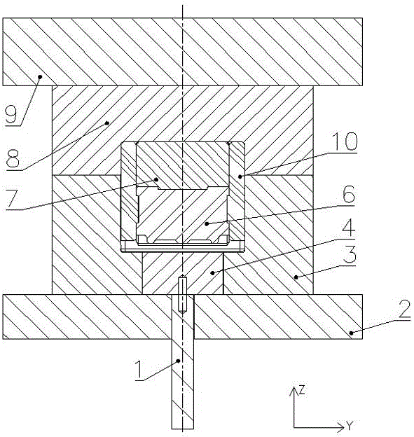
图1为本发明实施例提供的承载鞍多向模锻成形模具的剖面图;Fig. 1 is a cross-sectional view of a bearing saddle multi-directional forging forming die provided by an embodiment of the present invention;
图2为图1中A-A剖面图;Fig. 2 is A-A sectional view among Fig. 1;
图3为本发明实施例提供的上凸模部分组装图;Figure 3 is a partial assembly view of the upper punch provided by the embodiment of the present invention;
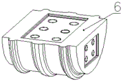
图4为本发明实施例提供的上冲头半圆台的立体图;Figure 4 is a perspective view of the upper punch semi-circular table provided by the embodiment of the present invention;
图5为本发明实施例提供的下模芯的立体图;Figure 5 is a perspective view of the lower mold core provided by the embodiment of the present invention;
图6为本发明实施例提供的下模块的立体图;Fig. 6 is a perspective view of a lower module provided by an embodiment of the present invention;
图7为本发明实施例提供的下凹模的剖面图;Fig. 7 is the sectional view of the lower die provided by the embodiment of the present invention;
图8为本发明实施例提供的圆棒料初始放置位置图;Figure 8 is a diagram of the initial placement position of the round bar provided by the embodiment of the present invention;
图9为本发明实施例提供的下模块复位、水平冲头尖部预定义后的下模组件的剖面图;Fig. 9 is a cross-sectional view of the lower mold assembly after the lower module is reset and the tip of the horizontal punch is predefined according to the embodiment of the present invention;
图10 为本发明实施例提供的锻造完成图;Fig. 10 is the forging completion figure provided by the embodiment of the present invention;
图中标记为:1、下顶杆;2、下模芯垫板;3、下模芯;4、下模块;5、水平冲头尖部;6、上冲头半圆台;7、上冲头顶板;8、上冲头连接板;9、上模芯垫板;10、上冲头侧板;11、定位弧形槽;12、圆棒料;13、承载鞍锻件。The marks in the figure are: 1. Lower ejector pin; 2. Lower mold core backing plate; 3. Lower mold core; 4. Lower module; 5. Tip of horizontal punch; 6. Upper punch semicircle platform; 7. Upper punch Head top plate; 8. Upper punch connecting plate; 9. Upper die core backing plate; 10. Upper punch side plate; 11. Positioning arc groove; 12. Round bar material; 13. Bearing saddle forging.
具体实施方式Detailed ways
为充分了解本发明之目的、特征及功效,借由下述具体的实施方式,对本发明做详细说明,但本发明并不仅仅限于此。In order to fully understand the purpose, features and effects of the present invention, the present invention will be described in detail through the following specific embodiments, but the present invention is not limited thereto.
一种承载鞍多向模锻成形模具,由上模、下模和水平冲头等组成,水平冲头由水平冲头根部、水平冲头连接杆、水平冲头尖部5等组成,上模、下模和水平冲头尖部5合模得到承载鞍形状的型腔结构,如图1和图2所示。A bearing saddle multi-directional die forging forming die is composed of an upper die, a lower die and a horizontal punch. The horizontal punch is composed of a horizontal punch root, a horizontal punch connecting rod, and a
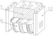
上模由上模芯垫板9、上冲头连接板8、上冲头侧板10、上冲头顶板7和上冲头半圆台6组成,上模芯垫板9下表面与上冲头连接板8上表面贴合,上冲头连接板8下表面中部开设有十字卡槽,十字卡槽中卡装有上冲头顶板7和上冲头侧板10。上冲头顶板7的X、Y轴长度尺寸均小于卡槽对应尺寸,单侧间隙为0.2mm。平行于Y轴的上冲头顶板7端面两侧分别贴合有上冲头侧板10,形成十字型结构,上冲头侧板10的外侧壁与上冲头连接板8十字卡槽的槽壁贴合。The upper die is composed of an upper die
如图3和图4所示,上冲头半圆台6与上冲头顶板7、上冲头半圆台6与上冲头侧板10采用方键定位、螺钉连接,具体结构为:上冲头半圆台6水平放置,弧形面朝下,水平面朝上,水平面中心开设有第一定位槽,上冲头顶板7的下表面中心设置有定位块,定位块嵌在定位槽中。上冲头半圆台6的弧形面设置有与承载鞍的鞍面环带、油槽相匹配的结构。上冲头半圆台6的两半圆形端面上分别开设有第二定位槽,上冲头侧板10侧壁下部设置有第二定位块,第二定位块嵌在第二定位槽中。As shown in Figure 3 and Figure 4, the upper punch semi-circular table 6 and the upper
上冲头顶板7下表面外缘与水平冲头尖部5上表面贴合,水平冲头尖部5插装在下模内。The outer edge of the lower surface of the upper
下模由下模芯3、下模块4、下模芯垫板2和下模套等组成,下模芯3轴向中心上部开设有与承载鞍中部主体结构相同的模具型腔,关于平行于Y轴的中心线对称的下模芯3的模具型腔侧壁分别开设有矩形缺口,缺口用于放置水平冲头尖部5,水平冲头尖部5为两块长方体块,每个缺口中放置一个长方体块。The lower mold is composed of the
下模芯3轴向中心下部开设有圆柱腔体,模具型腔与圆柱腔体连通,形成台阶状结构,圆柱腔体内装有滑动连接的下模块4,如图5所示。下模块4的上表面中心开设有定位弧形槽11,如图6所示,定位弧形槽11延伸至模具型腔的台阶上表面,利用定位弧形槽11限位圆棒料12,如图7所示。下模芯3的下表面与下模芯垫板2上表面贴合,下模芯垫板2放置在下模套上,下模芯垫板2的中心开设有通孔,通孔中装有滑动连接的下顶杆1,下顶杆1上端与下模块4下端通过圆柱销连接。A cylindrical cavity is provided at the lower part of the axial center of the
模具组装时,所有部件Z轴方向的对称中心线共线。上模与液压机活动横梁相连接,由液压机垂直缸提供垂直成形力,下模与液压机工作台连接,水平冲头尖部5与液压机水平缸连接,由水平缸提供水平成形力。When the mold is assembled, the symmetrical centerlines of all parts in the Z-axis direction are collinear. The upper mold is connected with the movable beam of the hydraulic press, and the vertical forming force is provided by the vertical cylinder of the hydraulic press, the lower mold is connected with the working table of the hydraulic press, and the
成形方法如下:The forming method is as follows:
S1、坯料下料:坯料采用Φ140mm圆棒料12,长度约260mm,该直径坯料可满足坯料长度与承载鞍锻件13长度尺寸相差不大,保证锻件的成形质量。S1. Blank blanking: The blank is made of
S2、模具安装:按模具结构安装模具,并保证模具安装时的定位精度及上模与下模的对中精度,对中精度不超过±0.3mm。S2. Mold installation: Install the mold according to the mold structure, and ensure the positioning accuracy of the mold installation and the alignment accuracy of the upper mold and the lower mold. The alignment accuracy does not exceed ±0.3mm.
S3、加热:坯料加热至始锻温度1220±20℃,保温时间不少于0.5h,总加热时间不少于1.2h,保证加热均匀;模具采用电加热带预热至200±20℃,总预热时间不少于4h。S3. Heating: The billet is heated to the initial forging temperature of 1220±20°C, the holding time is not less than 0.5h, and the total heating time is not less than 1.2h to ensure uniform heating; the mold is preheated to 200±20°C with an electric heating belt, and the total The warm-up time is not less than 4h.
S4、锻造:S4. Forging:
S4-1、坯料及模具达到设定温度,坯料满足保温时间要求后,出炉准备锻造。S4-1. After the billet and mold reach the set temperature, and the billet meets the holding time requirement, it is ready for forging.
S4-2、放置坯料:上模距下模上表面400mm(即下模芯上表面距离上冲头半圆台下表面的距离),下模块4沿Z轴上行约200mm,圆棒料12放置在下模块4的定位弧形槽11中,如图8所示,然后下模块4退回至初始位置,圆棒料12定位至下模芯3模具型腔底面。S4-2. Place the blank: the distance between the upper mold and the upper surface of the lower mold is 400mm (that is, the distance between the upper surface of the lower mold core and the lower surface of the semi-circular table of the upper punch), the
S4-3、水平冲头尖部5预定位:水平冲头尖部5提前预定义至下模芯3型腔内约10mm,如图9所示,以改善金属的流动情况,防止纵向飞边的产生。S4-3. Pre-positioning of the horizontal punch tip 5: the
S4-4、上模整体下行:上模采用位移控制方式,以满足高度尺寸要求,上模整体锻造至位移达到设定数值400mm时,停止下行。S4-4. The overall downward movement of the upper mold: the upper mold adopts a displacement control method to meet the height and dimension requirements. When the overall forging of the upper mold reaches the set value of 400mm, the downward movement is stopped.
S4-5、水平冲头尖部5对向挤压:水平冲头尖部5采用压力控制方式,以保证锻件充填质量;水平冲头尖部5沿X轴对向挤压至压力达到设定数值300bar时,水平冲头尖部5停止挤压,完成锻造过程,如图10所示。S4-5. Counter-extrusion at the tip of the horizontal punch 5: the tip of the
S4-6、转移锻件:上模整体沿Z轴上行并距下模整体上表面400mm(即下模芯上表面距离上冲头半圆台6下表面的距离),然后由下顶杆1、下模块4组成的下顶出机构顶出承载鞍锻件13,顶出高度200mm,由机械手转移至输送链。S4-6. Transferring forgings: The upper mold as a whole moves upward along the Z axis and is 400mm away from the overall upper surface of the lower mold (that is, the distance between the upper surface of the lower mold core and the lower surface of the semi-circular table 6 of the upper punch), and then the lower ejector rod 1, the lower The lower ejection mechanism composed of
承载鞍锻件热处理后,进行力学性能检测,分别从锻件顶面长度、宽度方向及侧面长度方向制备力学及冲击试样,试样加工至标准尺寸后,进行拉伸和冲击性能检测,力学性能检测结果见表1所示。After the heat treatment of the bearing saddle forgings, the mechanical properties are tested, and the mechanical and impact samples are prepared from the length of the top surface of the forging, the width direction and the side length direction. After the samples are processed to the standard size, the tensile and impact properties are tested, and the mechanical properties are tested. The results are shown in Table 1.
表1 承载鞍锻件力学性能Table 1 Mechanical properties of saddle forgings
由表1可知,锻件各方向力学性能实测平均值均高于最低标准值,且三个方向力学性能实测数据相差不大。采用多向模锻成形工艺生产的承载鞍锻件,材料在三个方向均受压,组织更加致密,产品性能更加均匀、优良。It can be seen from Table 1 that the measured average value of the mechanical properties of the forging in each direction is higher than the minimum standard value, and the measured data of the mechanical properties of the three directions are not much different. The bearing saddle forging produced by the multi-directional die forging forming process, the material is compressed in three directions, the structure is more compact, and the product performance is more uniform and excellent.
最后,需要注意的是:以上列举的仅是本发明的优选实施例,当然本领域的技术人员可以对本发明进行改动和变型,倘若这些修改和变型属于本发明权利要求及其等同技术的范围之内,均应认为是本发明的保护范围。Finally, it should be noted that: the above enumerations are only preferred embodiments of the present invention, and of course those skilled in the art can modify and modify the present invention, provided that these modifications and modifications belong to the scope of the claims of the present invention and their equivalent technologies All should be considered as the protection scope of the present invention.
Claims (7)
Applications Claiming Priority (2)
| Application Number | Priority Date | Filing Date | Title |
|---|---|---|---|
| CN2021109971966 | 2021-08-27 | ||
| CN202110997196.6A CN113751648A (en) | 2021-08-27 | 2021-08-27 | A bearing saddle forging forming die |
Publications (1)
| Publication Number | Publication Date |
|---|---|
| CN116078976A true CN116078976A (en) | 2023-05-09 |
Family
ID=78791692
Family Applications (2)
| Application Number | Title | Priority Date | Filing Date |
|---|---|---|---|
| CN202110997196.6A Pending CN113751648A (en) | 2021-08-27 | 2021-08-27 | A bearing saddle forging forming die |
| CN202210838388.7A Pending CN116078976A (en) | 2021-08-27 | 2022-07-18 | Multidirectional die forging forming die for bearing saddle |
Family Applications Before (1)
| Application Number | Title | Priority Date | Filing Date |
|---|---|---|---|
| CN202110997196.6A Pending CN113751648A (en) | 2021-08-27 | 2021-08-27 | A bearing saddle forging forming die |
Country Status (2)
| Country | Link |
|---|---|
| CN (2) | CN113751648A (en) |
| ZA (1) | ZA202109085B (en) |
Families Citing this family (2)
| Publication number | Priority date | Publication date | Assignee | Title |
|---|---|---|---|---|
| CN113751648A (en) * | 2021-08-27 | 2021-12-07 | 华北理工大学 | A bearing saddle forging forming die |
| CN113996740A (en) * | 2021-11-04 | 2022-02-01 | 华北理工大学 | Train bearing saddle forging forming method |
Citations (5)
| Publication number | Priority date | Publication date | Assignee | Title |
|---|---|---|---|---|
| CN105057528A (en) * | 2015-08-19 | 2015-11-18 | 郑州机械研究所 | Single-station multidirectional extrusion precision forming process of automobile steering piston |
| CN106734841A (en) * | 2016-12-20 | 2017-05-31 | 郑州机械研究所 | A kind of pair of flange multidirectional precision forming device of I-shaped stainless steel body |
| CN206912034U (en) * | 2017-05-19 | 2018-01-23 | 国网山东省电力公司平邑县供电公司 | One kind control cable anchor ear mould |
| KR20200082336A (en) * | 2018-12-28 | 2020-07-08 | 이유형 | Mold For Die Forging |
| CN113751648A (en) * | 2021-08-27 | 2021-12-07 | 华北理工大学 | A bearing saddle forging forming die |
-
2021
- 2021-08-27 CN CN202110997196.6A patent/CN113751648A/en active Pending
- 2021-11-16 ZA ZA2021/09085A patent/ZA202109085B/en unknown
-
2022
- 2022-07-18 CN CN202210838388.7A patent/CN116078976A/en active Pending
Patent Citations (5)
| Publication number | Priority date | Publication date | Assignee | Title |
|---|---|---|---|---|
| CN105057528A (en) * | 2015-08-19 | 2015-11-18 | 郑州机械研究所 | Single-station multidirectional extrusion precision forming process of automobile steering piston |
| CN106734841A (en) * | 2016-12-20 | 2017-05-31 | 郑州机械研究所 | A kind of pair of flange multidirectional precision forming device of I-shaped stainless steel body |
| CN206912034U (en) * | 2017-05-19 | 2018-01-23 | 国网山东省电力公司平邑县供电公司 | One kind control cable anchor ear mould |
| KR20200082336A (en) * | 2018-12-28 | 2020-07-08 | 이유형 | Mold For Die Forging |
| CN113751648A (en) * | 2021-08-27 | 2021-12-07 | 华北理工大学 | A bearing saddle forging forming die |
Also Published As
| Publication number | Publication date |
|---|---|
| CN113751648A (en) | 2021-12-07 |
| ZA202109085B (en) | 2022-03-30 |
Similar Documents
| Publication | Publication Date | Title |
|---|---|---|
| CN106734841B (en) | A kind of multidirectional precision forming device of I-shaped stainless steel body of double flanges | |
| CN201529706U (en) | Heavy truck bending beam plastic mold | |
| CN102029348A (en) | Multi-way die forging process method and mould for 40Cr steel case type parts | |
| CN202655596U (en) | Zinc alloy subbase die-casting mould | |
| CN116078966A (en) | Multidirectional die forging forming method for bearing saddle forging piece | |
| CN120023243B (en) | Hot stamping die with lateral air pressure loading device | |
| CN107774808A (en) | Adjustable molding blade mold of a kind of large-scale combined and preparation method thereof | |
| CN207770626U (en) | A kind of water heater bottom plate mold | |
| CN202224528U (en) | Universal bending die | |
| CN201862725U (en) | Multi-die-forging mold for part of 40 Cr steel machine case | |
| CN202239437U (en) | Die holder for hot die forging press | |
| CN204396805U (en) | A kind of cast ball line multistation penetrates sand machine | |
| CN101716669B (en) | Liquid forging device of multisection mold surface for universal oil hydraulic press | |
| CN207076936U (en) | Bushing pipe is injected in a kind of Press Tools for Automobiles manufacture | |
| CN102626764A (en) | Forming forging die for anchor chain crosspiece | |
| CN205289622U (en) | Spline shaft plain forging inlays mould | |
| CN205289623U (en) | Spline shaft plain forging mould | |
| CN215144003U (en) | Double-layer stamping die | |
| CN216884928U (en) | Precision mold with accurate positioning function | |
| CN217889261U (en) | Continuous punch forming device of chaplet for casting engine cylinder block | |
| CN103157737A (en) | U-type bolt preforming device | |
| CN209664110U (en) | Reflectal automotive wheels flaring die | |
| CN209664109U (en) | Reflectal wheel hub spinning mold with preheating device | |
| CN207709598U (en) | Sheet material bending mould | |
| CN223476164U (en) | Heat pipe forming device |
Legal Events
| Date | Code | Title | Description |
|---|---|---|---|
| PB01 | Publication | ||
| PB01 | Publication | ||
| SE01 | Entry into force of request for substantive examination | ||
| SE01 | Entry into force of request for substantive examination |