CN116073204A - A power distribution line switching device - Google Patents
A power distribution line switching device Download PDFInfo
- Publication number
- CN116073204A CN116073204A CN202310189243.3A CN202310189243A CN116073204A CN 116073204 A CN116073204 A CN 116073204A CN 202310189243 A CN202310189243 A CN 202310189243A CN 116073204 A CN116073204 A CN 116073204A
- Authority
- CN
- China
- Prior art keywords
- fixedly installed
- rod
- power distribution
- distribution line
- adapter
- Prior art date
- Legal status (The legal status is an assumption and is not a legal conclusion. Google has not performed a legal analysis and makes no representation as to the accuracy of the status listed.)
- Granted
Links
Images
Classifications
-
- H—ELECTRICITY
- H01—ELECTRIC ELEMENTS
- H01R—ELECTRICALLY-CONDUCTIVE CONNECTIONS; STRUCTURAL ASSOCIATIONS OF A PLURALITY OF MUTUALLY-INSULATED ELECTRICAL CONNECTING ELEMENTS; COUPLING DEVICES; CURRENT COLLECTORS
- H01R31/00—Coupling parts supported only by co-operation with counterpart
- H01R31/06—Intermediate parts for linking two coupling parts, e.g. adapter
-
- H—ELECTRICITY
- H01—ELECTRIC ELEMENTS
- H01R—ELECTRICALLY-CONDUCTIVE CONNECTIONS; STRUCTURAL ASSOCIATIONS OF A PLURALITY OF MUTUALLY-INSULATED ELECTRICAL CONNECTING ELEMENTS; COUPLING DEVICES; CURRENT COLLECTORS
- H01R13/00—Details of coupling devices of the kinds covered by groups H01R12/70 or H01R24/00 - H01R33/00
- H01R13/58—Means for relieving strain on wire connection, e.g. cord grip, for avoiding loosening of connections between wires and terminals within a coupling device terminating a cable
- H01R13/5804—Means for relieving strain on wire connection, e.g. cord grip, for avoiding loosening of connections between wires and terminals within a coupling device terminating a cable comprising a separate cable clamping part
-
- H—ELECTRICITY
- H01—ELECTRIC ELEMENTS
- H01R—ELECTRICALLY-CONDUCTIVE CONNECTIONS; STRUCTURAL ASSOCIATIONS OF A PLURALITY OF MUTUALLY-INSULATED ELECTRICAL CONNECTING ELEMENTS; COUPLING DEVICES; CURRENT COLLECTORS
- H01R13/00—Details of coupling devices of the kinds covered by groups H01R12/70 or H01R24/00 - H01R33/00
- H01R13/62—Means for facilitating engagement or disengagement of coupling parts or for holding them in engagement
- H01R13/629—Additional means for facilitating engagement or disengagement of coupling parts, e.g. aligning or guiding means, levers, gas pressure electrical locking indicators, manufacturing tolerances
- H01R13/631—Additional means for facilitating engagement or disengagement of coupling parts, e.g. aligning or guiding means, levers, gas pressure electrical locking indicators, manufacturing tolerances for engagement only
-
- H—ELECTRICITY
- H01—ELECTRIC ELEMENTS
- H01R—ELECTRICALLY-CONDUCTIVE CONNECTIONS; STRUCTURAL ASSOCIATIONS OF A PLURALITY OF MUTUALLY-INSULATED ELECTRICAL CONNECTING ELEMENTS; COUPLING DEVICES; CURRENT COLLECTORS
- H01R35/00—Flexible or turnable line connectors, i.e. the rotation angle being limited
Landscapes
- Patch Boards (AREA)
Abstract
Description
技术领域technical field
本发明涉及电力配电设备技术领域,具体为一种电力配电线路转接装置。The invention relates to the technical field of power distribution equipment, in particular to a power distribution line switching device.
背景技术Background technique
配电是在电力系统中直接与用户相连并向用户分配电能的环节。配电系统由配电变电所、高压配电线路、配电变压器、低压配电线路以及相应的控制保护设备组成,并且在配电的过程中,需要线路转接装置对电线进行转接,但是现有的转接装置对电线的固定效果较差,从而导致了电线在转接的过程中不够稳定,并且在转接的过程中,电线容易脱落,从而无法保证转接头的正常使用,给实际使用带来了一定的不利影响,因此需要进行改进。申请号为公开了一种线路转接装置,由两个配电线本体、铜丝和连接板,两个配电线本体的内壁均固定安装有铜丝、配电线本体的表面活动连接有连接板,连接板的两侧均固定连接有U形架,U形架的内部滑动插设有两个限位块,两个限位块的侧壁固定连接有凹槽板,U形架的内部螺纹插设有螺杆,螺杆用作驱动凹槽板向靠近配电线本体的一侧移动,凹槽板的内壁设有固定件,固定件为锥刺,解决了直接将两根配电线上的铜丝缠绕在一起的话两根配电线容易在拉直受力的状况下出现脱落的问题。但是,该方案凹槽板中设置刺锥易将电缆皮刺穿,造成损伤。Power distribution is a link in the power system that is directly connected to users and distributes electric energy to users. The power distribution system consists of power distribution substations, high-voltage distribution lines, distribution transformers, low-voltage distribution lines and corresponding control and protection equipment, and in the process of power distribution, a line switching device is required to switch the wires. However, the existing switching devices have a poor fixing effect on the wires, which leads to the instability of the wires during the switching process, and the wires are easy to fall off during the switching process, so that the normal use of the switching joints cannot be guaranteed. The actual use has brought some adverse effects, so it needs to be improved. The application number is to disclose a line transfer device, which consists of two distribution line bodies, copper wires and connecting plates. The connecting plate is fixedly connected with a U-shaped frame on both sides of the connecting plate. Two limit blocks are slidingly inserted inside the U-shaped frame. The side walls of the two limit blocks are fixedly connected with groove plates. The U-shaped frame A screw is inserted into the internal thread, and the screw is used to drive the grooved plate to move to the side close to the body of the distribution line. The inner wall of the grooved plate is provided with a fixing piece, which is a cone thorn, which solves the problem of directly connecting two distribution lines. If the copper wires on the wire are entangled together, the two power distribution wires are prone to fall off under the condition of straightening and stress. However, the thorn awl provided in the grooved plate of this scheme is easy to pierce the cable skin and cause damage.
对此,研发一种新的电力配电线路转接装置以替代现有的转接装置,解决在转接的过程中电线容易脱落的问题。In this regard, a new power distribution line switching device is developed to replace the existing switching device, and to solve the problem that the wires are easy to fall off during the switching process.
发明内容Contents of the invention
本发明的目的在于提供一种电力配电线路转接装置,具备的固定装置实现了对电线的夹持固定,从而能够提高电线转接的稳固性,并且能够进一步防止电线脱落,保证转接头的正常使用,具备的转动装置能够对转接头进行转动,从而能够对转接头的转接角度进行调整,进而便于工作人员对电线进行转接安装,给实际使用带来了一定的有利影响,解决了以上背景技术中提出的问题。The purpose of the present invention is to provide a power distribution line transfer device. The fixing device provided can clamp and fix the wires, thereby improving the stability of the wire transfer, and can further prevent the wires from falling off, ensuring the safety of the transfer joint. In normal use, the rotating device can rotate the adapter, so that the angle of the adapter can be adjusted, and it is convenient for the staff to install the wires, which has a certain beneficial effect on actual use and solves the problem of The problems raised in the background art above.
为实现上述目的,本发明提供如下技术方案:一种电力配电线路转接装置,包括转接头,转接头的底部固定安装有转轴,转轴的底端通过轴承转动连接有调节筒,调节筒的内部设有调节杆,调节杆的底端穿出调节筒固定连接有安装板,转接头的上下两侧固定安装有滑杆,滑杆的另一端固定安装有限位块,滑杆的外部滑动连接有滑套,滑套的底部固定安装有连接杆,连接杆的另一端固定安装有螺母,螺母的另一侧固定安装有拉环,螺母的内部螺纹连接有螺杆,螺杆的一端固定连接有转杆,螺杆的另一端固定安装有弧形固定板。In order to achieve the above object, the present invention provides the following technical solutions: a power distribution line transfer device, including a transfer joint, the bottom of the transfer joint is fixedly installed with a rotating shaft, and the bottom end of the rotating shaft is rotatably connected with an adjustment cylinder through a bearing, and the adjustment cylinder There is an adjustment rod inside, the bottom end of the adjustment rod passes through the adjustment cylinder and is fixedly connected to the installation plate, the upper and lower sides of the adapter are fixedly installed with a sliding rod, the other end of the sliding rod is fixedly installed with a limit block, and the external sliding connection of the sliding rod There is a sliding sleeve, the bottom of the sliding sleeve is fixedly installed with a connecting rod, the other end of the connecting rod is fixedly installed with a nut, the other side of the nut is fixedly installed with a pull ring, the inner thread of the nut is connected with a screw rod, and one end of the screw rod is fixedly connected with a rotating rod. rod, and the other end of the screw rod is fixedly installed with an arc-shaped fixing plate.
优选的,调节筒的右侧且靠近其底部设有固定螺栓,调节杆的右侧开设有若干个固定槽,固定螺栓的左端穿进固定筒的内部与固定槽相互卡接且适配。Preferably, a fixing bolt is provided on the right side of the adjusting cylinder and close to its bottom, and several fixing grooves are opened on the right side of the adjusting rod, and the left end of the fixing bolt penetrates into the inside of the fixing cylinder and engages and fits with the fixing groove.
优选的,安装板的底部固定安装有绝缘板,绝缘板为PVC材料。Preferably, an insulating board is fixedly installed on the bottom of the installation board, and the insulating board is made of PVC material.
优选的,转接头的两侧固定安装有密封环,密封环的直径与转接口的内径相同。Preferably, sealing rings are fixedly installed on both sides of the adapter, and the diameter of the seal ring is the same as the inner diameter of the adapter.
优选的,转轴的外部固定安装有齿环,齿环的右侧活动连接有齿轮,齿轮的底端底部固定安装有转动杆,转动杆的底端固定安装有旋钮,转动杆的外部转动连接有转动套,转动套的左侧与调节筒固定连接。Preferably, a gear ring is fixedly installed on the outside of the rotating shaft, and a gear is movably connected to the right side of the gear ring. Rotating sleeve, the left side of the rotating sleeve is fixedly connected with the adjusting cylinder.
优选的,滑杆的外侧固定安装有弹簧,弹簧的另一端与连接杆固定连接。Preferably, a spring is fixedly installed on the outer side of the slide bar, and the other end of the spring is fixedly connected to the connecting rod.
优选的,弧形固定板的内侧固定安装有防滑垫,防滑垫的内部固定连接有防滑颗粒。Preferably, an anti-slip pad is fixedly installed on the inner side of the arc-shaped fixing plate, and anti-slip particles are fixedly connected to the inside of the anti-slip pad.
与现有技术相比,本发明的有益效果是:转杆转动能够带动螺杆进行转动,螺杆能够在转动的同时带动弧形固定板进行移动,弧形固定板能够对电线进行夹持固定,从而能够提高电线转接的稳固性,并且滑杆的外侧固定安装有弹簧,弹簧的另一端与连接杆固定连接,在弹簧的弹性作用下,使得电线能够与转接头连接的更加紧固,从而能够进一步防止电线脱落,保证转接头的正常使用,并且旋钮转动能够带动转动杆进行转动,转动杆能够带动齿轮进行转动,齿轮能够带动齿环进行转动,齿环能够带动转轴进行转动,转轴能够带动转接头进行转动,从而能够对转接头的转接角度进行调整,进而便于工作人员对电线进行转接安装。Compared with the prior art, the beneficial effect of the present invention is that the rotation of the rotating rod can drive the screw to rotate, and the screw can drive the arc-shaped fixing plate to move while rotating, and the arc-shaped fixing plate can clamp and fix the electric wire, thereby The stability of the wire transfer can be improved, and a spring is fixedly installed on the outside of the slide bar, and the other end of the spring is fixedly connected to the connecting rod. Further prevent the wire from falling off and ensure the normal use of the adapter, and the rotation of the knob can drive the rotation rod to rotate, the rotation rod can drive the gear to rotate, the gear can drive the gear ring to rotate, the gear ring can drive the shaft to rotate, and the shaft can drive the rotation The joint is rotated so that the transition angle of the transition joint can be adjusted, thereby facilitating staff to perform transition installation on the electric wires.
附图说明Description of drawings
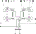
图1为本发明的结构示意图;Fig. 1 is a structural representation of the present invention;
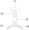
图2为本发明的夹持装置结构示意图;Fig. 2 is the structural representation of clamping device of the present invention;
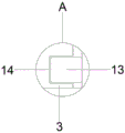
图3为本发明的A处放大图;Fig. 3 is the enlarged view of A place of the present invention;
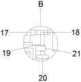
图4为本发明的B处放大图。Fig. 4 is an enlarged view of B of the present invention.
图中:1、转接头;2、调节筒;3、调节杆;4、安装板;5、滑杆;6、滑套;7、连接杆;8、螺母;9、拉环;10、螺杆;11、转杆;12、弧形固定板;13、固定螺栓;14、固定槽;15、绝缘板;16、密封环;17、齿环;18、齿轮;19、转动杆;20、旋钮;21、转动套;22、弹簧;23、防滑垫。In the figure: 1. Adapter; 2. Adjusting cylinder; 3. Adjusting rod; 4. Mounting plate; 5. Slider; 6. Sliding sleeve; 7. Connecting rod; 8. Nut; 9. Pull ring; 10. Screw ;11, rotating rod; 12, arc-shaped fixed plate; 13, fixed bolt; 14, fixed slot; 15, insulating plate; 16, sealing ring; 17, gear ring; 18, gear; 19, rotating rod; 20, knob ; 21, rotating sleeve; 22, spring; 23, anti-skid pad.
具体实施方式Detailed ways
下面将结合本发明实施例中的附图,对本发明实施例中的技术方案进行清楚、完整地描述,显然,所描述的实施例仅仅是本发明一部分实施例,而不是全部的实施例。基于本发明中的实施例,本领域普通技术人员在没有做出创造性劳动前提下所获得的所有其他实施例,都属于本发明保护的范围。The following will clearly and completely describe the technical solutions in the embodiments of the present invention with reference to the accompanying drawings in the embodiments of the present invention. Obviously, the described embodiments are only some, not all, embodiments of the present invention. Based on the embodiments of the present invention, all other embodiments obtained by persons of ordinary skill in the art without making creative efforts belong to the protection scope of the present invention.
实施例1,请参阅图1至图4,本发明提供一种技术方案:一种电力配电线路转接装置,包括转接头1,转接头1的底部固定安装有转轴,转轴的底端通过轴承转动连接有调节筒2,调节筒2的内部设有调节杆3,调节杆3的底端穿出调节筒2固定连接有安装板4,转接头1的上下两侧固定安装有滑杆5,滑杆5的另一端固定安装有限位块,滑杆5的外部滑动连接有滑套6,滑套6的底部固定安装有连接杆7,连接杆7的另一端固定安装有螺母8,螺母8的另一侧固定安装有拉环9,螺母8的内部螺纹连接有螺杆10,螺杆10的一端固定连接有转杆11,螺杆10的另一端固定安装有弧形固定板12。
进一步的,调节筒2的右侧且靠近其底部设有固定螺栓13,调节杆3的右侧开设有若干个固定槽14,固定螺栓13的左端穿进固定筒的内部与固定槽14相互卡接且适配,通过固定槽14和固定螺栓13的设置,实现了对转接头1与安装位置之间距离的调节,从而提高了转接装置的适用性,并且方便工作人员进行转接操作。Further, the right side of the adjusting
进一步的,安装板4的底部固定安装有绝缘板15,绝缘板15为PVC材料,绝缘板15能够在安装位置和转接头1之间起到绝缘的作用,从而能够防止电线短路,保证转接头1使用的安全性。Further, an
进一步的,转接头1的两侧固定安装有密封环16,密封环16的直径与转接口的内径相同,密封环16能够提高转接头1接口与电线之间的密封性,进而能够防止外部灰尘和雨水进入到转接头1的内部。Further,
实施例2,请参阅图1至图4,本实施例与实施例1的区别在于:转轴的外部固定安装有齿环17,齿环17的右侧活动连接有齿轮18,齿轮18的底端底部固定安装有转动杆19,转动杆19的底端固定安装有旋钮20,转动杆19的外部转动连接有转动套21,转动套21的左侧与调节筒2固定连接,在转动杆19和转动套21的转动作用下,能够稳定的对转接头1的转接角度进行调整,滑杆5的外侧固定安装有弹簧22,弹簧22的另一端与连接杆7固定连接,在弹簧22的弹性作用下,使得电线能够与转接头1连接的更加紧固,从而能够进一步防止电线脱落,弧形固定板12的内侧固定安装有防滑垫23,防滑垫23的内部固定连接有防滑颗粒,防滑垫23能够增大弧形固定板12与电线之间的摩擦,从而能够防止电线在转接的过程中出现滑动的情况。
工作原理:该一种电力配电线路转接装置在用时,工作人员能够通过安装板4对转接装置进行安装,并且调节筒2的右侧且靠近其底部设有固定螺栓13,调节杆3的右侧开设有若干个固定槽14,固定螺栓13的左端穿进固定筒的内部与固定槽14相互卡接且适配,通过固定槽14和固定螺栓13的设置,实现了对转接头1与安装位置之间距离的调节,从而提高了转接装置的适用性,并且方便工作人员进行转接操作,同时工作人员能够转动旋钮20,旋钮20转动能够带动转动杆19进行转动,转动杆19能够带动齿轮18进行转动,齿轮18能够带动齿环17进行转动,齿环17能够带动转轴进行转动,转轴能够带动转接头1进行转动,从而能够对转接头1的转接角度进行调整,进而便于工作人员对电线进行转接安装,角度调节完成后,工作人员能够将电线插入转接头1两端的接口中,并且工作人员能够箱外侧拉动拉环9,同时工作人员能够转动转杆11,转杆11转动能够带动螺杆10进行转动,螺杆10能够在转动的同时带动弧形固定板12进行移动,弧形固定板12能够对电线进行夹持固定,从而能够提高电线转接的稳固性,并且滑杆5的外侧固定安装有弹簧22,弹簧22的另一端与连接杆7固定连接,在弹簧22的弹性作用下,使得电线能够与转接头1连接的更加紧固,从而能够进一步防止电线脱落,保证转接头1的正常使用。Working principle: When this kind of power distribution line transfer device is in use, the staff can install the transfer device through the
尽管已经示出和描述了本发明的实施例,对于本领域的普通技术人员而言,可以理解在不脱离本发明的原理和精神的情况下可以对这些实施例进行多种变化、修改、替换和变型,本发明的范围由所附权利要求及其等同物限定。Although the embodiments of the present invention have been shown and described, those skilled in the art can understand that various changes, modifications and substitutions can be made to these embodiments without departing from the principle and spirit of the present invention. and modifications, the scope of the invention is defined by the appended claims and their equivalents.
Claims (8)
Priority Applications (1)
| Application Number | Priority Date | Filing Date | Title |
|---|---|---|---|
| CN202310189243.3A CN116073204B (en) | 2023-03-02 | 2023-03-02 | Switching device for power distribution line |
Applications Claiming Priority (1)
| Application Number | Priority Date | Filing Date | Title |
|---|---|---|---|
| CN202310189243.3A CN116073204B (en) | 2023-03-02 | 2023-03-02 | Switching device for power distribution line |
Publications (2)
| Publication Number | Publication Date |
|---|---|
| CN116073204A true CN116073204A (en) | 2023-05-05 |
| CN116073204B CN116073204B (en) | 2023-07-25 |
Family
ID=86171497
Family Applications (1)
| Application Number | Title | Priority Date | Filing Date |
|---|---|---|---|
| CN202310189243.3A Active CN116073204B (en) | 2023-03-02 | 2023-03-02 | Switching device for power distribution line |
Country Status (1)
| Country | Link |
|---|---|
| CN (1) | CN116073204B (en) |
Citations (7)
| Publication number | Priority date | Publication date | Assignee | Title |
|---|---|---|---|---|
| DE4322443A1 (en) * | 1993-07-06 | 1995-01-12 | Eaton Controls Gmbh | Electrical connecting device |
| JP2021129489A (en) * | 2020-02-11 | 2021-09-02 | 楽 康Le, Kang | New energy car charging device |
| CN214543583U (en) * | 2021-04-15 | 2021-10-29 | 国网湖北省电力有限公司巴东县供电公司 | Distribution lines switching device |
| CN214626314U (en) * | 2021-05-17 | 2021-11-05 | 吴教明 | Power distribution line switching device |
| CN113629638A (en) * | 2021-09-09 | 2021-11-09 | 国网山东省电力公司龙口市供电公司 | A high-voltage power fitting for power lines |
| CN218183448U (en) * | 2022-08-29 | 2022-12-30 | 山东纳方电子工程有限公司 | Anti-drop structure is connected to switch |
| CN218182967U (en) * | 2022-07-19 | 2022-12-30 | 云南润楠建设工程有限公司 | Electric power fitting for overhead line |
-
2023
- 2023-03-02 CN CN202310189243.3A patent/CN116073204B/en active Active
Patent Citations (7)
| Publication number | Priority date | Publication date | Assignee | Title |
|---|---|---|---|---|
| DE4322443A1 (en) * | 1993-07-06 | 1995-01-12 | Eaton Controls Gmbh | Electrical connecting device |
| JP2021129489A (en) * | 2020-02-11 | 2021-09-02 | 楽 康Le, Kang | New energy car charging device |
| CN214543583U (en) * | 2021-04-15 | 2021-10-29 | 国网湖北省电力有限公司巴东县供电公司 | Distribution lines switching device |
| CN214626314U (en) * | 2021-05-17 | 2021-11-05 | 吴教明 | Power distribution line switching device |
| CN113629638A (en) * | 2021-09-09 | 2021-11-09 | 国网山东省电力公司龙口市供电公司 | A high-voltage power fitting for power lines |
| CN218182967U (en) * | 2022-07-19 | 2022-12-30 | 云南润楠建设工程有限公司 | Electric power fitting for overhead line |
| CN218183448U (en) * | 2022-08-29 | 2022-12-30 | 山东纳方电子工程有限公司 | Anti-drop structure is connected to switch |
Also Published As
| Publication number | Publication date |
|---|---|
| CN116073204B (en) | 2023-07-25 |
Similar Documents
| Publication | Publication Date | Title |
|---|---|---|
| CN209104703U (en) | A kind of distribution line termination | |
| CN211377431U (en) | Novel power transmission and transformation line wire is fixed device | |
| CN110224239A (en) | A kind of parallel groove clamp | |
| CN208723132U (en) | Self-adapting electric rotatable flexible grounding wire device | |
| CN109066130A (en) | Self-adapting electric rotatable flexible grounding wire device | |
| CN206758672U (en) | One kind ground wire fixture | |
| CN208256937U (en) | Duck tongue type spiral compression formula earthing clamp | |
| CN218678402U (en) | Sealed cable distribution box | |
| CN210074198U (en) | Variable angle earth clamp | |
| CN116073204B (en) | Switching device for power distribution line | |
| CN211957955U (en) | Grounding wire clamp for bus bridge | |
| CN112408074B (en) | Paying-off equipment for cable processing | |
| CN210380181U (en) | Six-split spacing rod | |
| CN204558688U (en) | Earthing clamp | |
| CN107528276A (en) | A kind of fixing device of electrical lead | |
| CN203774690U (en) | Pay-off device for power line erecting | |
| CN208131861U (en) | The dedicated bend wire apparatus of electric power secondary circuit | |
| CN208127772U (en) | A kind of communications equipment room weak-current cable deployment device | |
| CN219067391U (en) | A wiring device for electrical engineering | |
| CN217239953U (en) | Cable crimping pincers that electric power engineering used | |
| CN113690795B (en) | 220 kilovolt transmission line wire repairing device | |
| CN204205402U (en) | UHVDC Transmission Lines changes tangent tower wire clamp tool | |
| CN104201611B (en) | UHVDC Transmission Lines change tangent tower wire clamp tool | |
| CN205376813U (en) | Electrified lapping wire connector for power distribution electric network | |
| CN202455015U (en) | Adjustable linear four-hook fastener |
Legal Events
| Date | Code | Title | Description |
|---|---|---|---|
| PB01 | Publication | ||
| PB01 | Publication | ||
| SE01 | Entry into force of request for substantive examination | ||
| SE01 | Entry into force of request for substantive examination | ||
| GR01 | Patent grant | ||
| GR01 | Patent grant |