CN115977372A - Hanging basket operation system - Google Patents
Hanging basket operation system Download PDFInfo
- Publication number
- CN115977372A CN115977372A CN202211222685.5A CN202211222685A CN115977372A CN 115977372 A CN115977372 A CN 115977372A CN 202211222685 A CN202211222685 A CN 202211222685A CN 115977372 A CN115977372 A CN 115977372A
- Authority
- CN
- China
- Prior art keywords
- display device
- wire rope
- operation system
- hanging basket
- platform
- Prior art date
- Legal status (The legal status is an assumption and is not a legal conclusion. Google has not performed a legal analysis and makes no representation as to the accuracy of the status listed.)
- Pending
Links
Images
Landscapes
- Control And Safety Of Cranes (AREA)
Abstract
Description
技术领域technical field
本申请涉及工程施工作业技术领域,具体而言,涉及一种吊篮作业系统。The present application relates to the technical field of engineering construction operations, in particular to a hanging basket operation system.
背景技术Background technique
吊篮是建筑工程外墙立面保温、涂饰、幕墙等高空作业的施工设施,一般由悬挂机构、行程限位开关、安全锁、提升机、重锤、电器箱、悬吊平台、工作钢丝绳、安全钢丝绳和屋顶悬挂点组成。吊篮是利用提升机驱动悬吊平台,通过钢丝绳沿建筑外立面上下运行的施工作业设施,也是为外墙作业人员设置的作业平台,在高层或多层建筑的外墙施工、幕墙设置、保温施工和维修清洗外墙等工作中得到广泛使用。使用吊篮,可避免搭设外脚手架,施工作业过程中可随时观察外墙立面施工效果,发现问题可及时调整;与外墙脚手架造价对比可大幅降低施工成本,提高工作效率。目前吊篮施工存在以下问题:悬吊平台容易由于风力和钢丝绳的无限制摆动导致摇摆过渡。The hanging basket is a construction facility for high-altitude operations such as exterior wall facade insulation, coating, and curtain walls in construction projects. Composed of safety wire ropes and roof suspension points. The hanging basket is a construction operation facility that uses a hoist to drive a suspension platform, and runs up and down along the building's facade through a steel wire rope. It is also a working platform for exterior wall workers. It is widely used in thermal insulation construction and maintenance and cleaning of exterior walls. Using the hanging basket can avoid setting up external scaffolding. During the construction process, the construction effect of the external wall facade can be observed at any time, and problems can be adjusted in time. Compared with the cost of external wall scaffolding, the construction cost can be greatly reduced and work efficiency can be improved. At present, the following problems exist in the construction of hanging baskets: the suspension platform is prone to swing transition due to the wind force and the unlimited swing of the wire rope.
发明内容Contents of the invention
本申请实施例的目的在于提供一种吊篮作业系统,能够避免吊篮作业系统超负荷使用,使悬吊平台同步提升、下降时不易倾斜,稳定降落。The purpose of the embodiments of the present application is to provide a hanging basket operation system, which can avoid overloading of the hanging basket operation system, and make the suspension platform synchronously lifted and lowered so that it is not easy to tilt and falls stably.
本申请实施例提供的吊篮作业系统包括:悬挂机构;悬吊平台、工作钢丝绳、安全钢丝绳、U型锁套、安全锁、重锤、万向轮、底座;The hanging basket operation system provided in the embodiment of the present application includes: a suspension mechanism; a suspension platform, a working wire rope, a safety wire rope, a U-shaped lock sleeve, a safety lock, a weight, a universal wheel, and a base;
所述工作钢丝绳的第一端和所述悬挂机构连接;The first end of the working wire rope is connected to the suspension mechanism;
所述工作钢丝绳的第二端和所述悬吊平台连接;The second end of the working wire rope is connected to the suspension platform;
所述安全钢丝绳第一端和所述悬挂机构连接;The first end of the safety wire rope is connected to the suspension mechanism;
所述U型锁套设置在所述悬吊平台上;The U-shaped lock sleeve is arranged on the suspension platform;
所述安全钢丝绳第二端穿过所述安全锁、所述U型锁套和所述重锤连接;The second end of the safety wire rope is connected through the safety lock, the U-shaped lock sleeve and the weight;
所述底座开设有上口和下口;The base is provided with an upper opening and a lower opening;
所述底座呈空腔状,所述空腔用于容纳所述万向轮;The base is in the shape of a cavity, and the cavity is used to accommodate the universal wheel;
所述万向轮的尺寸小于所述下口、大于所述上口;The size of the universal wheel is smaller than the lower port and larger than the upper port;
所述万向轮自所述下口进入所述空腔,顶部延伸出所述上口,和所述重锤连接。The universal wheel enters the cavity from the lower opening, and the top extends out of the upper opening to connect with the weight.
在上述实现过程中,本申请实施例提供了一种重锤的设置方式,相比于现有技术,本申请首先设置了U型锁套,对安全钢丝绳的上半部分的活动范围进行限制,从而使得重锤稳固,在另一方面,需要安装规范保持重锤在施工过程中的灵活度。因此,设置万向轮,所述重锤和所述万向轮连接;所述万向轮固定在所述底座中;所述底座开设有上口;所述上口的直径小于所述万向轮的直径;所述上口的直径大于所述重锤的直径;所述万向轮顶部穿过所述上口与重锤连接。通过万向轮,使得重锤的在施工的过程中灵活移动。万向轮下方设置底座,底座上开设上口,上口的尺寸大于重锤的尺寸,万向轮顶部穿过上口与重锤连接。使得重锤在施工过程中能灵活运动。基于上述实施方式,最大限度的满足规范要求的钢丝绳摆动功能,同时避免无约束的摆动造成突然的大风等外力推动下造成吊篮摆动失控的功能。In the above implementation process, the embodiment of the present application provides a setting method of a heavy hammer. Compared with the prior art, the present application firstly sets a U-shaped lock sleeve to limit the movable range of the upper part of the safety wire rope. Thereby making the heavy hammer stable, on the other hand, installation specifications are required to maintain the flexibility of the heavy hammer during the construction process. Therefore, a universal wheel is provided, and the weight is connected to the universal wheel; the universal wheel is fixed in the base; the base is provided with an upper opening; the diameter of the upper opening is smaller than that of the universal The diameter of the wheel; the diameter of the upper port is greater than the diameter of the weight; the top of the universal wheel passes through the upper port and is connected with the weight. Through the universal wheel, the heavy hammer can move flexibly during the construction process. A base is arranged below the universal wheel, and an upper opening is provided on the base, the size of the upper opening is greater than the size of the weight, and the top of the universal wheel passes through the upper opening and is connected with the weight. It enables the heavy hammer to move flexibly during the construction process. Based on the above-mentioned implementation mode, the swing function of the steel wire rope required by the specification can be satisfied to the greatest extent, and at the same time, the function of uncontrolled swing of the hanging basket caused by external forces such as sudden strong winds can be avoided.
进一步地,所述U型锁套水平设置于所述吊篮底部的第一侧面;Further, the U-shaped lock sleeve is horizontally arranged on the first side of the bottom of the hanging basket;
所述第一侧面和所述安全锁的设置方向垂直。The first side is perpendicular to the installation direction of the safety lock.
进一步地,所述吊篮作业系统还包括:拉力传感器、工作钢丝绳、显示装置;Further, the hanging basket operation system also includes: a tension sensor, a working wire rope, and a display device;
所述工作钢丝绳的第一端和所述悬挂机构连接;The first end of the working wire rope is connected to the suspension mechanism;
所述工作钢丝绳的第二端和所述悬吊平台连接;The second end of the working wire rope is connected to the suspension platform;
所述拉力传感器设置在所述安全钢丝绳和所述工作钢丝绳上;The tension sensor is arranged on the safety wire rope and the working wire rope;
所述拉力传感器和所述显示装置连接;The tension sensor is connected to the display device;
所述显示装置用于根据所述拉力传感器的数值获取并显示所述悬吊平台的荷载值。The display device is used to obtain and display the load value of the suspension platform according to the value of the tension sensor.
在上述实现过程中,安全钢丝绳和工作钢丝绳上设置有拉力传感器,拉力传感器和显示装置连接,显示装置能够根据拉力传感器获取并显示悬吊平台对荷载值,基于上述实施方式,能够保证悬吊平台保持稳定,保证施工人员的安全。In the above implementation process, the safety wire rope and the working wire rope are provided with a tension sensor, and the tension sensor is connected to the display device. The display device can obtain and display the load value of the suspension platform according to the tension sensor. Based on the above implementation, it can ensure that the suspension platform Keep stable to ensure the safety of construction workers.
进一步地,所述吊篮作业系统还包括:Further, the hanging basket operation system also includes:
控制箱、提升机;Control box, hoist;
所述提升机和所述工作钢丝绳连接;The hoist is connected to the working wire rope;
所述控制箱和所述显示装置连接;The control box is connected to the display device;
所述控制箱设置在所述悬吊平台上;The control box is arranged on the suspension platform;
所述控制箱内设置有十轴惯性姿态传感器;A ten-axis inertial attitude sensor is arranged in the control box;
所述显示装置和所述提升机连接;The display device is connected to the hoist;
所述显示装置用于根据所述十轴惯性姿态传感器的数据控制所述提升机对所述工作钢丝绳进行调节。The display device is used to control the hoist to adjust the working wire rope according to the data of the ten-axis inertial attitude sensor.
在上述实现过程中,驱动提升机用于驱动工作钢丝绳工作,悬吊平台上设置有控制箱,控制箱内设置有十轴惯性姿态传感器,显示装置可以根据十轴惯性姿态传感器的数据控制所述提升机对所述工作钢丝绳进行调节,从而可以在悬吊平台倾斜的时候对悬挑平台的角度进行调整,使悬吊平台保持水平。In the above implementation process, the driving hoist is used to drive the working wire rope to work, the suspension platform is provided with a control box, and a ten-axis inertial attitude sensor is arranged in the control box, and the display device can control the said machine according to the data of the ten-axis inertial attitude sensor. The hoist adjusts the working wire rope, so that the angle of the suspended platform can be adjusted when the suspended platform is tilted, so that the suspended platform remains horizontal.
进一步地,所述吊篮作业系统包括:微型风机;Further, the hanging basket operation system includes: a micro fan;
所述微型风机设置在所述悬吊平台的两侧;The micro fan is arranged on both sides of the suspension platform;
所述微型风机和所述显示装置连接;The micro fan is connected to the display device;
所述显示装置用于根据所述十轴惯性姿态传感器的数据控制所述微型风机的工作状态。The display device is used to control the working state of the micro fan according to the data of the ten-axis inertial attitude sensor.
在上述实现过程中,利用微型风机正转、倒转产生的空气动力协助吊篮调整前后摆动姿态,显示装置可根据十轴惯性姿态传感器的测量数据在调整吊篮倾斜的同时通过指令使微型风机施加作用力,控制调整吊篮动态摆动。悬吊平台受外力摆动时,显示装置发送指令至微型风机,根据吊悬吊平台动姿态及趋势,驱动微型风机产生相反的作用力,带动悬吊平台停止摆动回归平衡。In the above implementation process, the aerodynamic force generated by the forward rotation and reverse rotation of the micro fan is used to assist the hanging platform to adjust the forward and backward swing posture. The force is used to control and adjust the dynamic swing of the gondola. When the suspension platform is swayed by external force, the display device sends instructions to the micro-fan, and according to the dynamic posture and trend of the suspension platform, the micro-fan is driven to generate the opposite force, driving the suspension platform to stop swinging and return to balance.
进一步地,所述吊篮作业系统包括:激光测距传感器、激光投射板;Further, the hanging basket operation system includes: a laser ranging sensor, a laser projection board;
所述激光测距传感器设置在所述悬吊平台的两侧;The laser ranging sensor is arranged on both sides of the suspension platform;
所述激光投射板设置在所述悬吊平台的大臂的端面;The laser projection board is arranged on the end face of the boom of the suspension platform;
所述激光测距传感器的激光向上投射;The laser light of the laser ranging sensor is projected upward;
所述激光测距传感器与所述显示装置连接;The laser ranging sensor is connected to the display device;
所述显示装置用于根据激光传感器的数据发出告警信息。The display device is used for sending out warning information according to the data of the laser sensor.
在上述实现过程中,悬吊平台的两侧设置有激光测距传感器,激光测距传感器的激光向上投射,激光测距传感器将测量到的数据发送到显示装置,显示装置根据激光测距传感器的数据可以获取当前悬吊平带的高度数据并进行显示。In the above implementation process, laser ranging sensors are installed on both sides of the suspension platform, and the laser light of the laser ranging sensor is projected upwards. The data can obtain the height data of the current suspension flat belt and display it.
进一步地,所述吊篮作业系统包括:弹簧减震器;Further, the hanging basket operation system includes: a spring shock absorber;
所述弹簧减震器设置在所述悬吊平台的底部。The spring shock absorber is arranged at the bottom of the suspension platform.
在上述实现过程中,悬吊平台的底部安装弹簧减震器,辅助减震,避免震动造成作业人员身体不适。In the above implementation process, a spring shock absorber is installed at the bottom of the suspension platform to assist in shock absorption and avoid physical discomfort caused by vibration.
进一步地,所述吊篮作业系统还包括:客户端;Further, the hanging basket operation system also includes: a client;
所述显示装置和客户端连接;The display device is connected to the client;
所述显示装置还用于将所述显示装置接收的数据发送到所述客户端。The display device is further configured to send the data received by the display device to the client.
在上述实现过程中,显示装置将获取到的数据发送到客户端,可以使得工作人员通过终端及时获取吊篮作业系统的工作状态,实时监控。In the above implementation process, the display device sends the obtained data to the client, which enables the staff to obtain the working status of the hanging basket operation system in time through the terminal and monitor it in real time.
进一步地,所述吊篮作业系统还包括:云端;Further, the hanging basket operation system also includes: the cloud;
所述显示装置和云端连接;The display device is connected to the cloud;
所述显示装置还用于将所述显示装置接收的数据发送到所述云端进行存储。The display device is further configured to send the data received by the display device to the cloud for storage.
在上述实现过程中,显示装置将接收的信息发送到云端进行存储,可以便于后续对数据进行管理、分析。In the above implementation process, the display device sends the received information to the cloud for storage, which can facilitate subsequent data management and analysis.
进一步地,所述吊篮作业系统包括:声光报警器;Further, the hanging basket operation system includes: an audible and visual alarm;
所述声光报警器和所述显示装置连接;The sound and light alarm is connected to the display device;
所述声光报警器用于根据所述显示装置发送的信号发出警报。The sound and light alarm is used to issue an alarm according to the signal sent by the display device.
在上述实现过程中,声光报警器可以及时发出警报,使工作人员提高警惕。In the above implementation process, the sound and light alarm can issue an alarm in time to make the staff more vigilant.
本申请公开的其他特征和优点将在随后的说明书中阐述,或者,部分特征和优点可以从说明书推知或毫无疑义地确定,或者通过实施本申请公开的上述技术即可得知。Other features and advantages disclosed in the present application will be described in the subsequent description, or some of the features and advantages can be deduced or unambiguously determined from the description, or can be known by implementing the above-mentioned technology disclosed in the present application.
为使本申请的上述目的、特征和优点能更明显易懂,下文特举较佳实施例,并配合所附附图,作详细说明如下。In order to make the above-mentioned purpose, features and advantages of the present application more comprehensible, preferred embodiments will be described in detail below together with the accompanying drawings.
附图说明Description of drawings
为了更清楚地说明本申请实施例的技术方案,下面将对本申请实施例中所需要使用的附图作简单地介绍,应当理解,以下附图仅示出了本申请的某些实施例,因此不应被看作是对范围的限定,对于本领域普通技术人员来讲,在不付出创造性劳动的前提下,还可以根据这些附图获得其他相关的附图。In order to more clearly illustrate the technical solutions of the embodiments of the present application, the accompanying drawings that need to be used in the embodiments of the present application will be briefly introduced below. It should be understood that the following drawings only show some embodiments of the present application, so It should not be regarded as a limitation on the scope, and those skilled in the art can also obtain other related drawings according to these drawings without creative work.
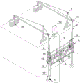
图1为本申请实施例提供的吊篮作业系统的结构示意图;Fig. 1 is the structural representation of the hanging basket operation system provided by the embodiment of the present application;
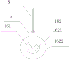
图2为本申请实施例提供的万向轮组件的结构示意图;Fig. 2 is a schematic structural view of the universal wheel assembly provided by the embodiment of the present application;
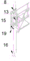
图3为本申请实施例提供的吊篮作业系统的局部结构示意图;Fig. 3 is a partial structural schematic diagram of the hanging basket operation system provided by the embodiment of the present application;
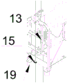
图4为本申请实施例提供的吊篮作业系统的局部结构示意图;Fig. 4 is a partial structural schematic diagram of the hanging basket operation system provided by the embodiment of the present application;
图5为本申请实施例提供的吊篮作业系统的内部结构示意图。Fig. 5 is a schematic diagram of the internal structure of the hanging basket operation system provided by the embodiment of the present application.
图标:1-悬挂机构;2-行程限位开关;3-安全锁;4-提升机;5-重锤;6-悬吊平台;7-工作钢丝绳;8-安全钢丝绳;9-安全绳;10-建筑梁柱;11-控制箱;12-拉力传感器;13-激光测距传感器;14-激光投射板;15-U型锁套;16-万向轮组件;18-声光报警器;19-弹簧减震器;20-配重传感器;161-万向轮;1621-上口;1622-下口;162-底座;A-显示装置;B-云端;C-客户端;D-微型风机。Icons: 1-suspension mechanism; 2-travel limit switch; 3-safety lock; 4-hoist; 5-weight hammer; 6-suspension platform; 7-working wire rope; 8-safety wire rope; 9-safety rope; 10-Building beams and columns; 11-Control box; 12-Tension sensor; 13-Laser ranging sensor; 14-Laser projection board; 15-U-shaped lock sleeve; 16-Universal wheel assembly; 19-spring shock absorber; 20-counterweight sensor; 161-universal wheel; 1621-upper port; 1622-lower port; 162-base; A-display device; B-cloud; C-client; D-miniature fan.
具体实施方式Detailed ways
下面将结合本申请实施例中的附图,对本申请实施例中的技术方案进行描述。The technical solutions in the embodiments of the present application will be described below with reference to the drawings in the embodiments of the present application.
应注意到:相似的标号和字母在下面的附图中表示类似项,因此,一旦某一项在一个附图中被定义,则在随后的附图中不需要对其进行进一步定义和解释。同时,在本申请的描述中,术语“第一”、“第二”等仅用于区分描述,而不能理解为指示或暗示相对重要性。It should be noted that like numerals and letters denote similar items in the following figures, therefore, once an item is defined in one figure, it does not require further definition and explanation in subsequent figures. Meanwhile, in the description of the present application, the terms "first", "second" and the like are only used to distinguish descriptions, and cannot be understood as indicating or implying relative importance.
实施例Example
参见图1、图2、图3、图4,本申请实施例提供一种吊篮作业系统,包括:悬挂机构1;悬吊平台6、工作钢丝绳7、安全钢丝绳8、U型锁套15、安全锁3、重锤5、万向轮161、底座162;所述工作钢丝绳7的第一端和所述悬挂机构1连接;所述工作钢丝绳7的第二端和所述悬吊平台6连接;所述安全钢丝绳8第一端和所述悬挂机构1连接;所述U型锁套15设置在所述悬吊平台6上;所述安全钢丝绳8第二端穿过所述安全锁3、所述U型锁套15和所述重锤5连接;所述重锤5和所述万向轮161连接;所述底座162开设有上口1621和下口1622;底座162呈空腔状,所述空腔用于容纳所述万向轮161;所述万向轮161的尺寸小于所述下口1622、大于所述上口1621;所述万向轮161自所述下口1622进入所述空腔,所述万向轮161的顶部延伸出所述上口1621,和所述重锤连接。Referring to Figure 1, Figure 2, Figure 3, and Figure 4, the embodiment of the present application provides a hanging basket operation system, including: a suspension mechanism 1; a suspension platform 6, a working wire rope 7, a safety wire rope 8, a U-shaped lock sleeve 15, Safety lock 3, weight 5, universal wheel 161, base 162; the first end of the working wire rope 7 is connected to the suspension mechanism 1; the second end of the working wire rope 7 is connected to the suspension platform 6 The first end of the safety wire rope 8 is connected to the suspension mechanism 1; the U-shaped lock sleeve 15 is arranged on the suspension platform 6; the second end of the safety wire rope 8 passes through the safety lock 3, The U-shaped lock sleeve 15 is connected to the weight 5; the weight 5 is connected to the universal wheel 161; the base 162 is provided with an upper port 1621 and a lower port 1622; the base 162 is hollow, The cavity is used to accommodate the universal wheel 161; the size of the universal wheel 161 is smaller than the lower port 1622 and larger than the upper port 1621; the universal wheel 161 enters the universal wheel 161 from the lower port 1622 The cavity, the top of the universal wheel 161 extends out of the upper port 1621, and is connected with the weight.
所述万向轮161的尺寸小于所述下口1622、大于所述上口1621的意思是万向轮161能够从下口1622完全进入空腔,但是不能完全从上口1621出空腔。The size of the
参见图1,悬挂机构1具有两个,分别设置在建筑顶面,建筑顶面上有建筑梁柱10,每个悬挂机构1的第一端设置有配重块,第二端通过连接绳连接悬吊平台6的侧面,从而使得悬吊平台6保持平衡。Referring to Fig. 1, there are two suspension mechanisms 1, which are respectively arranged on the top surface of the building. There are building beams and
重锤5与万向轮161通过螺栓连接,重锤5留凹槽带孔,万向轮161设置有凸片,凸片带孔,两孔穿入螺栓连接。The
在上述实现过程中,本申请实施例提供了一种重锤5的设置方式,相比于现有技术,本申请首先设置了U型锁套15,对安全钢丝绳8的上半部分的活动范围进行限制,从而使得重锤5稳固,在另一方面,需要安装规范保持重锤5在施工过程中的灵活度。因此,设置万向轮161,所述重锤5和所述万向轮161连接;所述万向轮161固定在所述底座162中;所述底座162开设有上口1621;所述上口1621的直径小于所述万向轮161的直径;所述上口1621的直径大于所述重锤5的直径;所述万向轮161顶部穿过所述上口1621与重锤5连接。通过万向轮161,使得重锤5的在施工的过程中灵活移动。万向轮161下方设置底座162,底座162上开设上口1621,上口1621的尺寸大于重锤5的尺寸,并万向轮161顶部穿过上口1621与重锤5连接,使得重锤5在施工过程中能灵活运动。基于上述实施方式,最大限度的满足规范要求的钢丝绳摆动功能,同时避免无约束的摆动造成突然的大风等外力推动下造成吊篮摆动失控的功能。In the above implementation process, the embodiment of the present application provides a setting method of the
参见图2,为万向轮组件16的示意图,包括:重锤5、万向轮161、底座162、底座162上开设有上口1621、下口1622。Referring to FIG. 2 , it is a schematic diagram of the
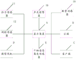
参见图5,在一种可能的实施方式中,配重件、工作钢丝绳7、显示装置A;所述配重件和所述悬吊平台6通过所述工作钢丝绳7悬挂于所述悬挂机构1两端;所述配重件上设置有配重传感器;所述配重传感器和所述显示装置连接。Referring to FIG. 5 , in a possible implementation manner, a counterweight, a working wire rope 7 , and a display device A; the counterweight and the suspension platform 6 are suspended from the suspension mechanism 1 through the working wire rope 7 two ends; the counterweight is provided with a counterweight sensor; the counterweight sensor is connected to the display device.
在上述实现过程中,配重件用于和悬吊平台6进行平衡,使悬吊平台6在工作过程中保持稳定,在配重件上设置了配重传感器20,配重传感器20和显示装置A连接,工作人员可以通过显示装置A及时地获取当前的配重块的重量,使悬吊平台6保持稳定,保证施工安全。In the above implementation process, the counterweight is used to balance the suspension platform 6, so that the suspension platform 6 remains stable during work, and a
系统还包括行程限位开关2、安全绳9等基本组件。The system also includes basic components such as
可以理解的是,显示装置A具有数据处理功能。It can be understood that the display device A has a data processing function.
在一种可能的实施方式中,系统还包括声光报警器18,声光报警器18和显示装置A连接。In a possible implementation manner, the system further includes an audible and
进一步地,显示装置A上设置有配重限制值,当显示装置A判断到配重传感器20的数值超过限制,控制声光报警器18发出警报,也可以通过显示界面发出警报。Further, the counterweight limit value is set on the display device A. When the display device A determines that the value of the
在一种可能的实施方式中,所述U型锁套水平设置于所述吊篮底部的第一侧面;In a possible implementation manner, the U-shaped lock sleeve is horizontally arranged on the first side of the bottom of the hanging basket;
所述第一侧面和所述安全锁的设置方向垂直。The first side is perpendicular to the installation direction of the safety lock.
在一种可能的实施方式中,U型锁套15由圆钢制成,U型锁套15外部套设有橡胶皮,可以避免圆钢磨损安全钢丝绳,也可以保证U型锁套15的强度。In a possible implementation, the
在一种可能的实施方式中,所述吊篮作业系统还包括:拉力传感器12;In a possible implementation manner, the hanging basket operation system further includes: a
所述拉力传感器12设置在所述工作钢丝绳7和安全钢丝绳8上;The
所述拉力传感器12和所述显示装置A连接;The
所述显示装置A用于根据所述拉力传感器12的数值获取并显示所述悬吊平台6的荷载值。The display device A is used to obtain and display the load value of the suspension platform 6 according to the value of the
可以理解的是,工作钢丝绳7和拉力传感器12之间的拉力包括于吊装平台的荷载力,这能够提高荷载计算的正确率。It can be understood that the tension between the working wire rope 7 and the
在上述实现过程中,工作钢丝绳7上设置有拉力传感器12,拉力传感器12和显示装置A连接,显示装置A能够根据拉力传感器12对数据获取并显示悬吊平台6对荷载值,基于上述实施方式,能够保证悬吊平台6保持稳定,保证施工人员的安全。拉力可对悬吊平台6荷载预设限值,通过两根工作钢丝绳的两个拉力传感器的监测数值对比,超过限值则启动报警。In the above implementation process, the working wire rope 7 is provided with a
安全钢丝绳8上的拉力传感器12是监测记录安全钢丝绳8底端重锤5对安全钢丝绳8应力的实际影响,由于工作钢丝绳7正常情况下承受吊篮荷载,安全钢丝绳8是在工作钢丝绳7断裂的情况下,应急生效锁定吊篮。The
在一种可能的实施方式中,控制箱11、提升机4;In a possible implementation manner, the
所述提升机4和所述工作钢丝绳7连接;The hoist 4 is connected to the working wire rope 7;
所述控制箱11和所述显示装置A连接;The
所述控制箱11设置在所述悬吊平台6上;The
所述控制箱11内设置有十轴惯性姿态传感器;The
所述显示装置A和所述提升机4连接;The display device A is connected to the hoist 4;
所述显示装置A用于根据所述十轴惯性姿态传感器的数据控制所述提升机4对所述工作钢丝绳7进行调节。The display device A is used to control the hoist 4 to adjust the working wire rope 7 according to the data of the ten-axis inertial attitude sensor.
上述实施例中,十轴惯性姿态传感器包括:三轴加速度传感器、三轴陀螺仪、三轴磁场传感器、三轴角度传感器、气压高度传感器、高度传感器、GPS传感器。用于进行态测量、倾角测量、震动测量、气压高度和GPS高度的融合测量。显示装置A可以利用十轴惯性姿态传感器监测的角度测量系统角度X、角度Y、角度Z数据传分析吊装平台前、后、左、右、上、下倾斜角度;利用气压高度和GPS高度的融合算法测量吊篮实时运行高度。In the above embodiment, the ten-axis inertial attitude sensor includes: a three-axis acceleration sensor, a three-axis gyroscope, a three-axis magnetic field sensor, a three-axis angle sensor, an air pressure altitude sensor, an altitude sensor, and a GPS sensor. It is used for fusion measurement of state measurement, inclination measurement, vibration measurement, barometric altitude and GPS altitude. The display device A can use the angle measurement system angle X, angle Y, and angle Z monitored by the ten-axis inertial attitude sensor to transmit and analyze the front, rear, left, right, up, and down tilt angles of the hoisting platform; use the fusion of barometric altitude and GPS altitude The algorithm measures the real-time running height of the gondola.
在上述实现过程中,所述驱动提升机4用于驱动工作钢丝绳,控制悬吊平台的悬吊高度,悬吊平台6上设置有控制箱11,控制箱11内设置有十轴惯性姿态传感器,显示装置A可以根据所述十轴惯性姿态传感器的数据控制所述提升机4对所述工作钢丝绳7进行调节,从而可以在悬吊平台6倾斜的时候对悬挑平台的角度进行调整,使悬吊平台6保持水平。In the above implementation process, the driving hoist 4 is used to drive the working wire rope to control the suspension height of the suspension platform. The suspension platform 6 is provided with a
在一种可能的实施方式中,所述吊篮作业系统包括:微型风机D;In a possible implementation manner, the hanging basket operation system includes: a micro blower D;
所述微型风机D设置在所述悬吊平台6的两侧;The micro fan D is arranged on both sides of the suspension platform 6;
所述微型风机D和所述显示装置A连接;The micro fan D is connected to the display device A;
所述显示装置A用于根据所述十轴惯性姿态传感器的数据控制所述微型风机D的工作状态。The display device A is used to control the working state of the micro fan D according to the data of the ten-axis inertial attitude sensor.
在上述实现过程中,利用微型风机D正转、倒转产生的空气动力协助吊篮调整前后摆动姿态,显示装置A可根据十轴惯性姿态传感器的测量数据在调整吊篮倾斜的同时通过指令使微型风机D施加作用力,控制调整吊篮动态摆动。悬吊平台6受外力摆动时,显示装置A发送指令至微型风机D,根据吊悬吊平台6动姿态及趋势,驱动微型风机D产生相反的作用力,带动悬吊平台6停止摆动回归平衡。In the above implementation process, the aerodynamic force generated by the forward rotation and reverse rotation of the miniature fan D is used to assist the hanging platform to adjust the forward and backward swing posture. Fan D exerts force to control and adjust the dynamic swing of the hanging basket. When the suspension platform 6 is swayed by external force, the display device A sends an instruction to the micro-fan D, and according to the movement posture and trend of the suspension platform 6, the micro-fan D is driven to generate the opposite force, and the suspension platform 6 stops swinging and returns to balance.
在一种可能的实施方式中,考虑到十轴姿态角度传感器E对尺寸监测非常灵敏,可在显示装置A系统内预设允许倾斜度,超过了允许倾斜度,才发送命令到提升机4以及微型风机D进行调整。In a possible implementation, considering that the ten-axis attitude angle sensor E is very sensitive to size monitoring, the allowable inclination can be preset in the display device A system, and the command is sent to the hoist 4 and The micro blower D is adjusted.
在一种可能的实施方式中,所述吊篮作业系统包括:激光测距传感器13、激光投射板14;In a possible implementation manner, the hanging basket operation system includes: a
所述激光测距传感器13设置在所述悬吊平台6的两侧;The
所述激光投射板14设置在所述悬吊平台6的大臂的端面;The
所述激光测距传感器13的激光向上投射;The laser light of the
所述激光测距传感器13与所述显示装置A连接;The
所述显示装置A用于根据激光传感器的数据发出告警信息。The display device A is used for sending out warning information according to the data of the laser sensor.
在上述实现过程中,悬吊平台6的两侧设置有激光测距传感器13,激光测距传感器13的激光向上投射,激光测距传感器13将测量到的数据发送到显示装置A,显示装置A根据激光测距传感器13的数据可以获取当前悬吊平带的高度数据并进行显示。In the above implementation process, the two sides of the suspension platform 6 are provided with laser
在一种可能的实施方式中,显示装置A还用于预设高位限位数值及低位限位数值;激光测距传感器13实测吊装平台运行接近高位预设值或低位预设值时,启动报警提示。In a possible implementation, the display device A is also used to preset the upper limit value and the lower limit value; when the
示例性地,当吊装平台的高度超过预设高位限位数值时,显示装置A控制声光报警器18发出警报,限制提升机4的工作状态,使吊装平台只能向下运行。当吊装平台的高度低于低位限位数值时,显示装置A控制发出警报。Exemplarily, when the height of the hoisting platform exceeds the preset high limit value, the display device A controls the audible and
进一步地,显示装置A上生成相关的触发按键,工作人员触发按键可以使显示装置A控制声光报警器18停止发出警报。Further, a relevant trigger key is generated on the display device A, and the staff triggers the key to make the display device A control the sound and
声光报警器18上也可以设置停止发出警报的按钮。The button that stops sending the alarm can also be set on the sound and
在一种可能的实施方式中,所述吊篮作业系统包括:弹簧减震器19;In a possible implementation manner, the hanging basket working system includes: a
所述弹簧减震器19设置在所述悬吊平台6的底部。The
在上述实现过程中,悬吊平台6的底部安装弹簧减震器19,辅助减震,避免震动造成作业人员身体不适。In the above implementation process, a
在一种可能的实施方式中,显示装置A还用于接收上下运行命令和工作高度,根据上下运行命令和运行高度,使提升机4进行工作,驱动吊装平台运行到工作高度。In a possible implementation, the display device A is also used to receive the up and down running command and the working height, and according to the up and down running command and the running height, make the hoist 4 work and drive the hoisting platform to run to the working height.
该工作高度是显示装置A根据激光测距传感器13和十轴姿态角度传感器E的数据计算得到的。The working height is calculated by the display device A according to the data of the
在一种可能的实施方式中,吊篮作业系统还包括:客户端C;In a possible implementation manner, the hanging basket operation system further includes: a client C;
所述显示装置A和客户端C连接;The display device A is connected to the client C;
所述显示装置A还用于将所述显示装置A接收的数据发送到所述客户端C。The display device A is further configured to send the data received by the display device A to the client C.
客户端C包括:APP客户端软件、微信小程序、网页小程序、电脑客户端软件等。Client C includes: APP client software, WeChat applets, webpage applets, computer client software, etc.
所述客户端C还设置有吊篮作业系统所在的工程项目的工程项目信息,所述吊篮工作系统内各个硬件的安装情况。The client C is also provided with project information of the engineering project where the hanging basket operation system is located, and the installation status of each hardware in the hanging basket working system.
显示装置A还用于接收客户端C的命令,根据客户端C命令是提升机4工作,控制吊装平台的工作高度。The display device A is also used to receive commands from the client C, and according to the commands from the client C, the hoist 4 works to control the working height of the hoisting platform.
所述客户端C软件还用于接收相关项目的信息、并根据相关项目的信息以及吊篮作业系统的工作状态信息判断当前是否已经到达检查或检修节点,若是,发出提示信息。The client C software is also used to receive the information of related items, and judge whether the inspection or maintenance node has been reached according to the information of related items and the working status information of the hanging basket operation system, and if so, send a prompt message.
所述客户端C软件还用于接收规范表格、相关项目的信息以及吊篮作业系统的工作状态信息在所述规范表格补充信息。The client C software is also used to receive the supplementary information in the specification form, the information of related items, and the working status information of the hanging basket operation system.
示例性地,该提示信息可以是弹窗等。Exemplarily, the prompt information may be a pop-up window or the like.
进一步地,吊篮作业系统还包括:云端B;所述显示装置A和云端B连接;所述显示装置A还用于将所述显示装置A接收的数据发送到所述云端B进行存储。Further, the hanging basket operation system further includes: a cloud B; the display device A is connected to the cloud B; the display device A is also used to send the data received by the display device A to the cloud B for storage.
在上述实现过程中,显示装置A将接收的信息发送到云端B进行存储,可以便于后续对数据进行管理、分析。In the above implementation process, the display device A sends the received information to the cloud B for storage, which can facilitate subsequent data management and analysis.
以上所述仅为本申请的实施例而已,并不用于限制本申请的保护范围,对于本领域的技术人员来说,本申请可以有各种更改和变化。凡在本申请的精神和原则之内,所作的任何修改、等同替换、改进等,均应包含在本申请的保护范围之内。应注意到:相似的标号和字母在下面的附图中表示类似项,因此,一旦某一项在一个附图中被定义,则在随后的附图中不需要对其进行进一步定义和解释。The above descriptions are only examples of the present application, and are not intended to limit the scope of protection of the present application. For those skilled in the art, various modifications and changes may be made to the present application. Any modifications, equivalent replacements, improvements, etc. made within the spirit and principles of this application shall be included within the protection scope of this application. It should be noted that like numerals and letters denote similar items in the following figures, therefore, once an item is defined in one figure, it does not require further definition and explanation in subsequent figures.
以上所述,仅为本申请的具体实施方式,但本申请的保护范围并不局限于此,任何熟悉本技术领域的技术人员在本申请揭露的技术范围内,可轻易想到变化或替换,都应涵盖在本申请的保护范围之内。因此,本申请的保护范围应所述以权利要求的保护范围为准。The above is only a specific implementation of the application, but the scope of protection of the application is not limited thereto. Anyone familiar with the technical field can easily think of changes or substitutions within the technical scope disclosed in the application. Should be covered within the protection scope of this application. Therefore, the protection scope of the present application should be based on the protection scope of the claims.
需要说明的是,在本文中,诸如第一和第二等之类的关系术语仅仅用来将一个实体或者操作与另一个实体或操作区分开来,而不一定要求或者暗示这些实体或操作之间存在任何这种实际的关系或者顺序。而且,术语“包括”、“包含”或者其任何其他变体意在涵盖非排他性的包含,从而使得包括一系列要素的过程、方法、物品或者设备不仅包括那些要素,而且还包括没有明确列出的其他要素,或者是还包括为这种过程、方法、物品或者设备所固有的要素。在没有更多限制的情况下,由语句“包括一个……”限定的要素,并不排除在包括所述要素的过程、方法、物品或者设备中还存在另外的相同要素。It should be noted that in this article, relational terms such as first and second are only used to distinguish one entity or operation from another entity or operation, and do not necessarily require or imply that there is a relationship between these entities or operations. There is no such actual relationship or order between them. Furthermore, the term "comprises", "comprises" or any other variation thereof is intended to cover a non-exclusive inclusion such that a process, method, article, or apparatus comprising a set of elements includes not only those elements, but also includes elements not expressly listed. other elements of or also include elements inherent in such a process, method, article, or device. Without further limitations, an element defined by the phrase "comprising a ..." does not exclude the presence of additional identical elements in the process, method, article or apparatus comprising said element.
Claims (10)
Priority Applications (1)
| Application Number | Priority Date | Filing Date | Title |
|---|---|---|---|
| CN202211222685.5A CN115977372A (en) | 2022-10-08 | 2022-10-08 | Hanging basket operation system |
Applications Claiming Priority (1)
| Application Number | Priority Date | Filing Date | Title |
|---|---|---|---|
| CN202211222685.5A CN115977372A (en) | 2022-10-08 | 2022-10-08 | Hanging basket operation system |
Publications (1)
| Publication Number | Publication Date |
|---|---|
| CN115977372A true CN115977372A (en) | 2023-04-18 |
Family
ID=85965286
Family Applications (1)
| Application Number | Title | Priority Date | Filing Date |
|---|---|---|---|
| CN202211222685.5A Pending CN115977372A (en) | 2022-10-08 | 2022-10-08 | Hanging basket operation system |
Country Status (1)
| Country | Link |
|---|---|
| CN (1) | CN115977372A (en) |
Cited By (3)
| Publication number | Priority date | Publication date | Assignee | Title |
|---|---|---|---|---|
| CN117145187A (en) * | 2023-08-29 | 2023-12-01 | 北京城建集团有限责任公司 | A method for installing a hanging basket without counterweight |
| CN118239410A (en) * | 2024-05-28 | 2024-06-25 | 江苏宇诚展览展示有限公司 | A lifting device for truss installation |
| CN118390788A (en) * | 2024-04-10 | 2024-07-26 | 安徽省建设监理有限公司 | Hanging basket safety monitoring system |
Citations (8)
| Publication number | Priority date | Publication date | Assignee | Title |
|---|---|---|---|---|
| CN2758369Y (en) * | 2004-12-20 | 2006-02-15 | 武汉市金泉绿色科技有限公司 | Mechanically driven altitude working hanging basket |
| CN201722117U (en) * | 2010-06-29 | 2011-01-26 | 廊坊凯博建设机械科技有限公司 | Light elevator hanging basket mounting device |
| CN101992976A (en) * | 2010-11-05 | 2011-03-30 | 沈阳建筑大学 | Automatic control system of high-operating hanging basket |
| CN202897966U (en) * | 2012-11-12 | 2013-04-24 | 天津市津渝恒安达机械设备有限公司 | Lifting control mechanism of electric hanging basket |
| CN108560896A (en) * | 2018-05-31 | 2018-09-21 | 江苏三浦电子科技有限公司 | Working at height anti-falling safe hanging basket |
| CN208039066U (en) * | 2018-03-30 | 2018-11-02 | 中建一局集团安装工程有限公司 | Movable bridge side construction operation platform |
| CN111255218A (en) * | 2020-01-19 | 2020-06-09 | 广东博智林机器人有限公司 | Split type hanging basket device |
| CN219654233U (en) * | 2022-10-08 | 2023-09-08 | 中交雄安建设有限公司 | Hanging basket operation system |
-
2022
- 2022-10-08 CN CN202211222685.5A patent/CN115977372A/en active Pending
Patent Citations (8)
| Publication number | Priority date | Publication date | Assignee | Title |
|---|---|---|---|---|
| CN2758369Y (en) * | 2004-12-20 | 2006-02-15 | 武汉市金泉绿色科技有限公司 | Mechanically driven altitude working hanging basket |
| CN201722117U (en) * | 2010-06-29 | 2011-01-26 | 廊坊凯博建设机械科技有限公司 | Light elevator hanging basket mounting device |
| CN101992976A (en) * | 2010-11-05 | 2011-03-30 | 沈阳建筑大学 | Automatic control system of high-operating hanging basket |
| CN202897966U (en) * | 2012-11-12 | 2013-04-24 | 天津市津渝恒安达机械设备有限公司 | Lifting control mechanism of electric hanging basket |
| CN208039066U (en) * | 2018-03-30 | 2018-11-02 | 中建一局集团安装工程有限公司 | Movable bridge side construction operation platform |
| CN108560896A (en) * | 2018-05-31 | 2018-09-21 | 江苏三浦电子科技有限公司 | Working at height anti-falling safe hanging basket |
| CN111255218A (en) * | 2020-01-19 | 2020-06-09 | 广东博智林机器人有限公司 | Split type hanging basket device |
| CN219654233U (en) * | 2022-10-08 | 2023-09-08 | 中交雄安建设有限公司 | Hanging basket operation system |
Cited By (4)
| Publication number | Priority date | Publication date | Assignee | Title |
|---|---|---|---|---|
| CN117145187A (en) * | 2023-08-29 | 2023-12-01 | 北京城建集团有限责任公司 | A method for installing a hanging basket without counterweight |
| CN118390788A (en) * | 2024-04-10 | 2024-07-26 | 安徽省建设监理有限公司 | Hanging basket safety monitoring system |
| CN118239410A (en) * | 2024-05-28 | 2024-06-25 | 江苏宇诚展览展示有限公司 | A lifting device for truss installation |
| CN118239410B (en) * | 2024-05-28 | 2024-07-26 | 江苏宇诚展览展示有限公司 | A lifting device for truss installation |
Similar Documents
| Publication | Publication Date | Title |
|---|---|---|
| ES2762858T3 (en) | Device and procedure for controlling an oscillation of a suspended load on a lifting device | |
| US12404149B2 (en) | Apparatus for controlling a load suspended on a cord | |
| JP2020503224A (en) | Apparatus for controlling the orientation of suspended loads | |
| CN101934990B (en) | Load moment limiter-based crawling crane anti-overturn device and method | |
| CN106829741B (en) | Driving tele-control system and control method | |
| CN101723239A (en) | Hanging hook attitude detection device and crane | |
| CN102259792A (en) | Improved orthogonal automatic horizontal adjustment lifting appliance and horizontal adjustment method thereof | |
| CN108560896A (en) | Working at height anti-falling safe hanging basket | |
| CN117387693A (en) | A digital twin attached lifting scaffold monitoring system and its monitoring method | |
| WO2021115496A2 (en) | Anti-slanting and anti-rocking monitoring apparatus displaying real time deflection angle of lifting hook, and crane | |
| CN219654233U (en) | Hanging basket operation system | |
| JP5287316B2 (en) | Elevator equipment | |
| CN103935916B (en) | Tower crane anti-over-tilt early warning method and tower crane anti-over-tilt early warning device | |
| CN116495624B (en) | Automatic monitoring device for safe operation of tower groups and control method thereof | |
| KR102447371B1 (en) | Apparatus and method for controlling posture and spraying operation of painting robot | |
| CN106556346A (en) | A kind of safety lock performance parameter non-contact measurement apparatus and its measuring method | |
| CN114457704A (en) | Hanging basket structure and safety monitoring method thereof | |
| CN211569893U (en) | Automatic stable balance system for crane hoisting | |
| CN113562639A (en) | Method and system for inhibiting vibration of tower body in hoisting and amplitude-changing process of crane | |
| Rishmawi | Tip-over stability analysis of crawler cranes in heavy lifting applications | |
| US12600604B2 (en) | Information acquisition system | |
| CN212425225U (en) | Group tower operation safety monitoring system | |
| CN217924779U (en) | Self-balancing suspension device | |
| CN210438292U (en) | Tower Crane Wireless Lifting Weight Monitoring System | |
| JPH09165186A (en) | Panel hanging device |
Legal Events
| Date | Code | Title | Description |
|---|---|---|---|
| PB01 | Publication | ||
| PB01 | Publication | ||
| SE01 | Entry into force of request for substantive examination | ||
| SE01 | Entry into force of request for substantive examination | ||
| CB03 | Change of inventor or designer information | ||
| CB03 | Change of inventor or designer information |
Inventor after: Chai Shaofeng Inventor after: Zhang Hongkun Inventor after: Li Wenhui Inventor after: Han Qiaoli Inventor after: Wang Zhenqi Inventor after: Lu Hailong Inventor after: Wang Zhenhao Inventor before: Han Qiaoli Inventor before: Wang Zhenqi Inventor before: Lu Hailong Inventor before: Wang Zhenhao |
|
| TA01 | Transfer of patent application right | ||
| TA01 | Transfer of patent application right |
Effective date of registration: 20230727 Address after: No. 1-103, Conference Center, South of Chentai Village Section, West Connecting Line of Xiongxian County, Baojin Expressway, Xiong'an District, China (Hebei) Pilot Free Trade Zone, Baoding City, Hebei Province, 071899 Applicant after: Zhongjiao Xiong'an Construction Co.,Ltd. Applicant after: Beijing Zhendong Lianke Technology Co.,Ltd. Address before: 101200 201-21478, zone 6, Xinggu Economic Development Zone, Pinggu District, Beijing Applicant before: Beijing Zhendong Lianke Technology Co.,Ltd. |
|
| RJ01 | Rejection of invention patent application after publication | ||
| RJ01 | Rejection of invention patent application after publication |
Application publication date: 20230418 |