CN115973979A - Glass bottle plastic cap screwing system and method - Google Patents
Glass bottle plastic cap screwing system and method Download PDFInfo
- Publication number
- CN115973979A CN115973979A CN202211392757.0A CN202211392757A CN115973979A CN 115973979 A CN115973979 A CN 115973979A CN 202211392757 A CN202211392757 A CN 202211392757A CN 115973979 A CN115973979 A CN 115973979A
- Authority
- CN
- China
- Prior art keywords
- glass bottle
- gear
- ratchet
- assembly
- tray
- Prior art date
- Legal status (The legal status is an assumption and is not a legal conclusion. Google has not performed a legal analysis and makes no representation as to the accuracy of the status listed.)
- Pending
Links
Images



Landscapes
- Sealing Of Jars (AREA)
Abstract
Description
技术领域technical field
本发明涉及塑料盖旋盖系统技术领域,具体为一种玻璃瓶塑料盖旋盖系统及方法。The invention relates to the technical field of plastic cap screwing systems, in particular to a glass bottle plastic cap screwing system and method.
背景技术Background technique
玻璃瓶在封盖时,通常使用塑料盖进行旋转式螺纹连接,而塑料盖在与玻璃瓶螺纹连接时,塑料盖与玻璃瓶的输料过程,因难以实现同步,导致玻璃瓶在输送至瓶盖处时,需要将玻璃瓶进行限位后,然后再使用夹具将瓶盖拧在玻璃瓶上,这样的生产方式,生产的效率不高,针对上述问题,发明人提出一种玻璃瓶塑料盖旋盖系统及方法用于解决上述问题。When the glass bottle is sealed, the plastic cap is usually used for rotary thread connection, and when the plastic cap is screwed to the glass bottle, the feeding process of the plastic cap and the glass bottle is difficult to achieve synchronization, resulting in the transfer of the glass bottle to the bottle. When the cap is placed, it is necessary to limit the position of the glass bottle, and then use the clamp to screw the cap on the glass bottle. This kind of production method has low production efficiency. In view of the above problems, the inventor proposes a plastic cap for the glass bottle The capping system and method are used to solve the above problems.
发明内容Contents of the invention
为了解决塑料盖与玻璃瓶的输料过程,因难以实现同步,导致玻璃瓶在输送至瓶盖处时,需要将玻璃瓶进行限位后,然后再使用夹具将瓶盖拧在玻璃瓶上,这样的生产方式,生产的效率不高问题;本发明的目的在于提供一种玻璃瓶塑料盖旋盖系统及方法。In order to solve the feeding process of plastic caps and glass bottles, it is difficult to achieve synchronization. When the glass bottles are transported to the caps, the glass bottles need to be limited, and then the caps are screwed on the glass bottles with clamps. In such a production mode, the production efficiency is not high; the purpose of the present invention is to provide a glass bottle plastic cap screw cap system and method.
为解决上述技术问题,本发明采用如下技术方案:一种玻璃瓶塑料盖旋盖系统,包括输送装置,所述输送装置包括有传送带,所述输送装置上安装有间歇装置和输料装置,所述输料装置上固定安装有夹持组件,所述间歇装置与传送带传动连接,所述间歇装置传动连接有旋转驱动组件,所述传送带上安装有多个限位组件,所述旋转驱动组件与限位组件传动连接,所述限位组件内套接安装有玻璃瓶组件,所述玻璃瓶组件包括有玻璃瓶体,所述玻璃瓶体上端螺纹连接有瓶盖,所述瓶盖设置于输料装置内,所述输送装置上固定安装有导向组件,所述导向组件与限位组件贴合连接,间歇装置传动传送带上的多个限位组件移动,使多个玻璃瓶体逐一移动至输料装置底端处,通过输料装置将瓶盖逐一输送至夹持组件内,然后旋转驱动组件传动玻璃瓶体转动,继而使玻璃瓶体与瓶盖螺纹连接。In order to solve the above technical problems, the present invention adopts the following technical solutions: a glass bottle plastic cap screwing system, including a conveying device, the conveying device includes a conveyor belt, and an intermittent device and a feeding device are installed on the conveying device. A clamping assembly is fixedly installed on the conveying device, the intermittent device is connected to the conveyor belt in transmission, the intermittent device is connected to a rotary drive assembly, and a plurality of limit assemblies are installed on the conveyor belt. The limit assembly is connected by transmission. The glass bottle assembly is sleeved in the limit assembly. The glass bottle assembly includes a glass bottle body. The upper end of the glass bottle body is screwed with a bottle cap. In the feeding device, a guide assembly is fixedly installed on the conveying device, and the guide assembly is closely connected with the limit assembly. The intermittent device drives the movement of multiple limit assemblies on the conveyor belt, so that multiple glass bottles move to the conveyor belt one by one. At the bottom of the feeding device, the bottle caps are conveyed one by one into the clamping assembly through the feeding device, and then the rotating drive assembly drives the glass bottle body to rotate, and then the glass bottle body and the bottle cap are screwed together.
优选地,所述输送装置包括有固定架,所述固定架上固定安装有两个安装板,所述安装板之间转动安装传送带,一个所述安装板侧面固定连接间歇装置,所述固定架上固定连接导向组件和旋转驱动组件,所述传送带上固定安装有多个安装块,所述安装块上表面滑动安装限位组件,导向组件能使移动至输料装置底端处的限位组件与旋转驱动组件传动连接;所述间歇装置包括有第一电机,所述第一电机固定设于一个安装板的侧面,所述第一电机的输出端固定连接有转盘、拨杆及半面齿轮,所述转盘上开设有第一弧形槽,所述拨杆传动连接有间歇盘,所述间歇盘上开设有第二弧形槽和矩形滑槽,所述转盘外表面贴合连接第二弧形槽内弧面,所述间歇盘与一个安装板的侧面转动连接,所述间歇盘内的轴与传送带传动连接,所述半面齿轮传动连接有齿板,所述齿板底端与安装板滑动连接,所述齿板的一端与旋转驱动组件传动连接,第一电机的输出端传动转盘、拨杆及半面齿轮转动,通过拨杆使间歇盘间歇性转动,使传送带间歇性移动,半面齿轮传动齿板往复移动;所述旋转驱动组件包括有第一导轨,所述第一导轨内滑动连接有棘齿条,所述棘齿条的一端高度连接有L形杆,所述L形杆与第一导轨滑动连接,所述第一导轨内侧与固定架固定连接,所述L形杆的一端固定连接齿板,所述第一导轨上固定连接有安装座,所述安装座上转动安装有棘爪和第一转轴,所述第一转轴外套设有棘轮,所述棘轮分别与棘爪、棘齿条啮合连接,所述第一转轴底端固定连接有第一齿轮,所述第一齿轮与限位组件传动连接,L形杆推动棘齿条沿第一导轨滑动,并能克服棘爪对棘轮的阻力,使第一转轴和第一齿轮转动,而L形杆反向移动时,棘齿条不能克服棘爪对棘轮的阻力,使棘轮空转。Preferably, the conveying device includes a fixed frame, and two mounting plates are fixedly installed on the fixed frame, the conveyor belt is rotated between the mounting plates, and the side of one of the mounting plates is fixedly connected to the intermittent device, and the fixed frame The upper part is fixedly connected with the guide assembly and the rotary drive assembly, and a plurality of installation blocks are fixedly installed on the conveyor belt. The upper surface of the installation block is slidably installed with a limit assembly. It is connected in transmission with the rotary drive assembly; the intermittent device includes a first motor, the first motor is fixed on the side of a mounting plate, and the output end of the first motor is fixedly connected with a turntable, a lever and a half-face gear, The turntable is provided with a first arc-shaped groove, and the driving rod is connected to an intermittent disk, and the intermittent disk is provided with a second arc-shaped groove and a rectangular chute, and the outer surface of the turntable is connected to the second arc-shaped groove. The inner arc surface of the shaped groove, the intermittent disk is connected to the side of a mounting plate in rotation, the shaft in the intermittent disk is connected to the transmission belt, the half-face gear is connected to the tooth plate, and the bottom end of the tooth plate is connected to the mounting plate Sliding connection, one end of the tooth plate is connected to the rotary drive assembly, the output end of the first motor drives the turntable, the lever and the half-face gear to rotate, and the intermittent plate rotates intermittently through the lever to make the conveyor belt move intermittently, and the half-face gear The transmission tooth plate reciprocates; the rotary drive assembly includes a first guide rail, a ratchet bar is slidably connected in the first guide rail, and an L-shaped bar is connected to the height of one end of the ratchet bar, and the L-shaped bar is connected to the The first guide rail is slidingly connected, the inner side of the first guide rail is fixedly connected with the fixed frame, one end of the L-shaped rod is fixedly connected to the tooth plate, the first guide rail is fixedly connected with a mounting seat, and the mounting seat is rotatably installed with The ratchet and the first rotating shaft, the first rotating shaft is covered with a ratchet, the ratchet is engaged with the ratchet and the ratchet rack respectively, the bottom end of the first rotating shaft is fixedly connected with a first gear, and the first gear Connected with the limit assembly, the L-shaped rod pushes the ratchet bar to slide along the first guide rail, and can overcome the resistance of the ratchet to the ratchet, so that the first rotating shaft and the first gear rotate, and when the L-shaped rod moves in the opposite direction, the ratchet The rack cannot overcome the resistance of the pawl to the ratchet, causing the ratchet to rotate idly.
优选地,所述限位组件包括有滑座,所述滑座固定设于安装块上表面,所述滑座上表面转动连接有第二转轴,所述第二转轴上端固定连接有卡筒,所述卡筒内套接安装玻璃瓶体,所述卡筒外表面固定设有齿环,所述齿环与第一齿轮啮合连接,所述滑座侧面固定设有弹簧,所述弹簧的一端与安装块固定连接,所述卡筒外表面贴合连接导向组件,滑座上转动连接的卡筒,且卡筒沿导向组件表面移动,使齿环与第一齿轮啮合连接;所述导向组件包括有T形板,所述T形板与固定架固定连接,所述T形板上固定连接有梯形块,所述梯形块侧面与卡筒外表面贴合连接,卡筒沿梯形块的表面滑动,使齿环与第一齿轮啮合连接,从而第一齿轮传动齿环转动;所述输料装置包括有支架,所述支架与固定架固定连接,所述支架上固定设有输料筒,所述输料筒内开设有圆通孔和多个环形槽,所述圆通孔内滑动安装瓶盖,所述输料筒外表面固定安装有第二电机,所述第二电机的输出端固定连接有第一托盘和第二托盘,所述第一托盘和第二托盘均转动设于环形槽内,第一托盘和第二托盘之间设置一个瓶盖,所述支架侧面固定连接夹持组件,当第二电机的输出端传动第一托盘和第二托盘转动,能使输料筒内的瓶盖逐一的输送出去;所述夹持组件包括有第二导轨,所述第二导轨固定设于支架的侧面,所述第二导轨内滑动安装有两个第一齿条,所述第二导轨侧面固定设有第三电机,所述第三电机的输出端固定设有第二齿轮,所述第二齿轮与第一齿条啮合连接,所述第一齿条的一端分别固定设有滑块,所述滑块与第二导轨滑动连接,所述滑块底面均固定设有弧形夹块,所述弧形夹块之间夹设安装瓶盖,第三电机的输出端传动第二齿轮转动,使两个第一齿条逆向滑动,继而使瓶盖被夹设安装于两个弧形夹块之间。Preferably, the limit assembly includes a sliding seat, the sliding seat is fixed on the upper surface of the mounting block, the upper surface of the sliding seat is rotatably connected to a second rotating shaft, and the upper end of the second rotating shaft is fixedly connected to a cartridge, A glass bottle body is sleeved inside the cartridge, a gear ring is fixed on the outer surface of the cartridge, and the gear ring is meshed with the first gear, and a spring is fixed on the side of the slide seat, and one end of the spring It is fixedly connected with the installation block, the outer surface of the cartridge is attached to the guide assembly, and the connected cartridge is rotated on the sliding seat, and the cartridge moves along the surface of the guide assembly, so that the gear ring is meshed with the first gear; the guide assembly It includes a T-shaped plate, the T-shaped plate is fixedly connected with the fixing frame, the trapezoidal block is fixedly connected to the T-shaped plate, the side of the trapezoidal block is connected with the outer surface of the cartridge, and the cartridge is along the surface of the trapezoidal block Sliding, so that the toothed ring meshes with the first gear, so that the first gear drives the toothed ring to rotate; the feeding device includes a bracket, the bracket is fixedly connected to the fixed frame, and the feeding tube is fixed on the bracket, A circular through hole and a plurality of annular grooves are opened in the conveying cylinder, a bottle cap is slidably installed in the circular through hole, a second motor is fixedly installed on the outer surface of the conveying cylinder, and the output end of the second motor is fixedly connected to There are a first tray and a second tray, the first tray and the second tray are both rotatably arranged in the annular groove, a bottle cap is arranged between the first tray and the second tray, the side of the bracket is fixedly connected to the clamping assembly, When the output end of the second motor drives the first tray and the second tray to rotate, the bottle caps in the feeding barrel can be conveyed out one by one; the clamping assembly includes a second guide rail, and the second guide rail is fixed on the On the side of the bracket, two first racks are slidably installed in the second guide rail, a third motor is fixed on the side of the second guide rail, and a second gear is fixed on the output end of the third motor. The second gear is meshed with the first rack, and one end of the first rack is respectively fixed with a slider, and the slider is slidably connected with the second guide rail, and the bottom surface of the slider is fixed with an arc clamping block , the bottle cap is sandwiched between the arc-shaped clamping blocks, and the output end of the third motor drives the second gear to rotate, so that the two first racks slide in reverse, and then the bottle cap is sandwiched and installed on the two arc-shaped clamping blocks. between the blocks.
一种玻璃瓶塑料盖旋盖方法,包括如下步骤:A method for screwing a plastic cap of a glass bottle, comprising the steps of:
步骤一:第一电机的输出端传动转盘、拨杆及半面齿轮转动,当拨杆转动脱离矩形滑槽时,转盘外表面贴合连接第二弧形槽内弧面,使间歇盘不会随惯性转动,使传送带间歇性转动,继而使多个安装块间歇性移动一段距离,并使多个卡筒内的玻璃瓶体逐一移动至输料筒底端处,转盘继续转动期间,半面齿轮传动齿板沿安装板滑动,使L形杆推动棘齿条沿第一导轨滑动,并能克服棘爪对棘轮的阻力,使第一转轴和第一齿轮转动,而第二电机的输出端传动第一托盘和第二托盘沿环形槽转动,第一托盘和第二托盘组合成圆形状,当第一托盘和第二托盘转动,能使输料筒内的瓶盖逐一的输送至两个弧形夹块之间,然后第三电机的输出端传动第二齿轮转动,使两个第一齿条反向滑动,并使两个弧形夹块内心移动,从而夹持固定瓶盖;Step 1: The output end of the first motor drives the turntable, the lever and the half-face gear to rotate. When the lever rotates away from the rectangular chute, the outer surface of the turntable fits and connects with the inner arc surface of the second arc groove, so that the intermittent plate will not follow Inertial rotation makes the conveyor belt rotate intermittently, and then makes multiple mounting blocks move intermittently for a certain distance, and makes the glass bottles in multiple cartridges move to the bottom of the feeding tube one by one. During the continuous rotation of the turntable, the half-face gear drives The tooth plate slides along the mounting plate, so that the L-shaped rod pushes the ratchet bar to slide along the first guide rail, and can overcome the resistance of the ratchet to the ratchet, so that the first shaft and the first gear rotate, and the output end of the second motor drives the first gear. The first tray and the second tray rotate along the annular groove, and the first tray and the second tray are combined into a circular shape. When the first tray and the second tray rotate, the bottle caps in the delivery tube can be conveyed to two arcs one by one. Between the clamping blocks, the output end of the third motor drives the second gear to rotate, so that the two first racks slide in reverse, and the two arc-shaped clamping blocks move inwardly, thereby clamping and fixing the bottle cap;
步骤二:卡筒通过安装块、传送带间歇移动时,卡筒沿梯形块表面移动,卡筒沿滑座滑动,并使弹簧形变,继而使卡筒外表面的齿环与第一齿轮啮合连接,而转动的第一齿轮使齿环和卡筒转动,继而使瓶盖能安装于玻璃瓶体上,而齿板反向滑动,使L形杆推动棘齿条沿第一导轨反向滑动时,棘齿条无法克服棘爪对棘轮的阻力,使棘轮沿第一转轴外表面空转,继而第一齿轮不会转动,从而被安装瓶盖的玻璃瓶体随着卡筒顺利的移动并远离输料筒底端。Step 2: When the cartridge moves intermittently through the mounting block and the conveyor belt, the cartridge moves along the surface of the trapezoidal block, the cartridge slides along the sliding seat, and the spring is deformed, and then the gear ring on the outer surface of the cartridge is meshed with the first gear, The rotating first gear rotates the gear ring and the card cylinder, and then the bottle cap can be installed on the glass bottle body, and the tooth plate slides in the opposite direction, so that when the L-shaped rod pushes the ratchet bar to slide in the reverse direction along the first guide rail, The ratchet rack cannot overcome the resistance of the ratchet to the ratchet, so that the ratchet rotates idly along the outer surface of the first rotating shaft, and then the first gear does not rotate, so that the glass bottle with the cap installed moves smoothly with the cartridge and away from the feeding material Bottom of barrel.
与现有技术相比,本发明的有益效果在于:Compared with prior art, the beneficial effect of the present invention is:
1、第二电机的输出端传动第一托盘和第二托盘沿环形槽转动,使输料筒内的瓶盖逐一的输送并被夹设安装两个弧形夹块之间,而玻璃瓶体安装于卡筒内,并随着传送带间歇性移动至瓶盖底端处,使玻璃瓶体和瓶盖的输料实现同步,协调性统一;1. The output end of the second motor drives the first tray and the second tray to rotate along the annular groove, so that the bottle caps in the feeding tube are conveyed one by one and are clamped and installed between two arc-shaped clamping blocks, while the glass bottle body Installed in the cartridge, and intermittently move to the bottom of the bottle cap with the conveyor belt, so that the feeding of the glass bottle body and the bottle cap can be synchronized and coordinated;
2、传送带停滞期间,L形杆推动棘齿条沿第一导轨滑动,并克服棘爪对棘轮的阻力,使第一齿轮传动齿环转动,继而使玻璃瓶体和瓶盖快速螺纹连接,完成玻璃瓶体的旋盖工作,且生产的效率高。2. During the stagnation of the conveyor belt, the L-shaped rod pushes the ratchet bar to slide along the first guide rail, and overcomes the resistance of the ratchet to the ratchet, so that the first gear drives the gear ring to rotate, and then the glass bottle body and the bottle cap are quickly threaded, and the completion The screw cap of the glass bottle body works, and the production efficiency is high.
附图说明Description of drawings
为了更清楚地说明本发明实施例或现有技术中的技术方案,下面将对实施例或现有技术描述中所需要使用的附图作简单地介绍,显而易见地,下面描述中的附图仅仅是本发明的一些实施例,对于本领域普通技术人员来讲,在不付出创造性劳动的前提下,还可以根据这些附图获得其他的附图。In order to more clearly illustrate the technical solutions in the embodiments of the present invention or the prior art, the following will briefly introduce the drawings that need to be used in the description of the embodiments or the prior art. Obviously, the accompanying drawings in the following description are only These are some embodiments of the present invention. Those skilled in the art can also obtain other drawings based on these drawings without creative work.
图1为本发明整体示意图。Fig. 1 is the overall schematic diagram of the present invention.
图2为本发明结构输送装置示意图。Fig. 2 is a schematic diagram of the structure delivery device of the present invention.
图3为本发明结构图2中A处放大示意图。Fig. 3 is an enlarged schematic diagram of A in Fig. 2 of the structure of the present invention.
图4为本发明结构限位组件示意图。Fig. 4 is a schematic diagram of the structure limiting assembly of the present invention.
图5为本发明结构旋转驱动组件和输料装置示意图。Fig. 5 is a schematic diagram of the rotary drive assembly and the feeding device of the structure of the present invention.
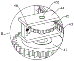
图6为本发明结构图5中B处放大示意图。Fig. 6 is an enlarged schematic diagram of B in Fig. 5 of the structure of the present invention.
图7为本发明结构图5中C处放大示意图。Fig. 7 is an enlarged schematic diagram of point C in Fig. 5 of the structure of the present invention.
图中:1、输送装置;11、固定架;12、安装板;13、传送带;14、安装块;2、间歇装置;21、第一电机;22、转盘;221、第一弧形槽;23、拨杆;24、间歇盘;241、第二弧形槽;242、矩形滑槽;25、半面齿轮;26、齿板;3、玻璃瓶组件;31、玻璃瓶体;32、瓶盖;4、旋转驱动组件;41、第一导轨;42、L形杆;43、棘齿条;44、安装座;45、棘轮;451、第一转轴;46、棘爪;47、第一齿轮;5、导向组件;51、T形板;52、梯形块;6、输料装置;61、支架;62、输料筒;621、圆通孔;622、环形槽;63、第二电机;64、第一托盘;65、第二托盘;7、夹持组件;71、第二导轨;72、第三电机;73、第二齿轮;74、第一齿条;75、滑块;76、弧形夹块;8、限位组件;81、滑座;811、第二转轴;82、弹簧;83、卡筒;84、齿环。In the figure: 1, conveying device; 11, fixed frame; 12, installation plate; 13, conveyor belt; 14, installation block; 2, intermittent device; 21, first motor; 22, turntable; 221, first arc groove; 23. Driving lever; 24. Intermittent plate; 241. Second arc groove; 242. Rectangular chute; 25. Half-face gear; 26. Tooth plate; 3. Glass bottle assembly; 31. Glass bottle body; 32. Bottle cap ;4, rotary drive assembly; 41, first guide rail; 42, L-shaped rod; 43, ratchet rack; 44, mounting seat; 45, ratchet wheel; 451, first rotating shaft; 46, ratchet; 47, first gear ;5, guide assembly; 51, T-shaped plate; 52, trapezoidal block; 6, feeding device; 61, bracket; 62, feeding cylinder; 621, round through hole; 622, annular groove; 63, second motor; 64 , the first tray; 65, the second tray; 7, the clamping assembly; 71, the second guide rail; 72, the third motor; 73, the second gear; 74, the first rack; 75, the slider; 76, the
具体实施方式Detailed ways
下面将结合本发明实施例中的附图,对本发明实施例中的技术方案进行清楚、完整地描述,显然,所描述的实施例仅仅是本发明一部分实施例,而不是全部的实施例。基于本发明中的实施例,本领域普通技术人员在没有做出创造性劳动前提下所获得的所有其他实施例,都属于本发明保护的范围。The following will clearly and completely describe the technical solutions in the embodiments of the present invention with reference to the accompanying drawings in the embodiments of the present invention. Obviously, the described embodiments are only some, not all, embodiments of the present invention. Based on the embodiments of the present invention, all other embodiments obtained by persons of ordinary skill in the art without making creative efforts belong to the protection scope of the present invention.
如图1-7所示,本发明提供了一种玻璃瓶塑料盖旋盖系统,包括输送装置1,所述输送装置1包括有传送带13,所述输送装置1上安装有间歇装置2和输料装置6,所述输料装置6上固定安装有夹持组件7,所述间歇装置2与传送带13传动连接,所述间歇装置2传动连接有旋转驱动组件4,所述传送带13上安装有多个限位组件8,所述旋转驱动组件4与限位组件8传动连接,所述限位组件8内套接安装有玻璃瓶组件3,所述玻璃瓶组件3包括有玻璃瓶体31,所述玻璃瓶体31上端螺纹连接有瓶盖32,所述瓶盖32设置于输料装置6内,所述输送装置1上固定安装有导向组件5,所述导向组件5与限位组件8贴合连接。As shown in Figures 1-7, the present invention provides a glass bottle plastic cap screwing system, including a conveying device 1, the conveying device 1 includes a
通过采用上述技术方案,间歇装置2传动传送带13上的多个限位组件8移动,使多个玻璃瓶体31逐一移动至输料装置6底端处,通过输料装置6将瓶盖32逐一输送至夹持组件7内,然后旋转驱动组件4传动玻璃瓶体31转动,继而使玻璃瓶体31与瓶盖32螺纹连接。By adopting the above-mentioned technical scheme, the
所述输送装置1包括有固定架11,所述固定架11上固定安装有两个安装板12,所述安装板12之间转动安装传送带13,一个所述安装板12侧面固定连接间歇装置2,所述固定架11上固定连接导向组件5和旋转驱动组件4,所述传送带13上固定安装有多个安装块14,所述安装块14上表面滑动安装限位组件8。The conveying device 1 includes a fixed
通过采用上述技术方案,导向组件5能使移动至输料装置6底端处的限位组件8与旋转驱动组件4传动连接。By adopting the above technical solution, the
所述间歇装置2包括有第一电机21,所述第一电机21固定设于一个安装板12的侧面,所述第一电机21的输出端固定连接有转盘22、拨杆23及半面齿轮25,所述转盘22上开设有第一弧形槽221,所述拨杆23传动连接有间歇盘24,所述间歇盘24上开设有第二弧形槽241和矩形滑槽242,所述转盘22外表面贴合连接第二弧形槽241内弧面,所述间歇盘24与一个安装板12的侧面转动连接,所述间歇盘24内的轴与传送带13传动连接,所述半面齿轮25传动连接有齿板26,所述齿板26底端与安装板12滑动连接,所述齿板26的一端与旋转驱动组件4传动连接。The
通过采用上述技术方案,第一电机21的输出端传动转盘22、拨杆23及半面齿轮25转动,通过拨杆23使间歇盘24间歇性转动,使传送带13间歇性移动,半面齿轮25传动齿板26往复移动。By adopting the above-mentioned technical scheme, the output end of the
所述旋转驱动组件4包括有第一导轨41,所述第一导轨41内滑动连接有棘齿条43,所述棘齿条43的一端高度连接有L形杆42,所述L形杆42与第一导轨41滑动连接,所述第一导轨41内侧与固定架11固定连接,所述L形杆42的一端固定连接齿板26,所述第一导轨41上固定连接有安装座44,所述安装座44上转动安装有棘爪46和第一转轴451,所述第一转轴451外套设有棘轮45,所述棘轮45分别与棘爪46、棘齿条43啮合连接,所述第一转轴451底端固定连接有第一齿轮47,所述第一齿轮47与限位组件8传动连接。The
通过采用上述技术方案,L形杆42推动棘齿条43沿第一导轨41滑动,并能克服棘爪46对棘轮45的阻力,使第一转轴451和第一齿轮47转动,而L形杆42反向移动时,棘齿条43不能克服棘爪46对棘轮45的阻力,使棘轮46空转。By adopting the above-mentioned technical scheme, the L-shaped
所述限位组件8包括有滑座81,所述滑座81固定设于安装块14上表面,所述滑座81上表面转动连接有第二转轴811,所述第二转轴811上端固定连接有卡筒83,所述卡筒83内套接安装玻璃瓶体31,所述卡筒83外表面固定设有齿环84,所述齿环84与第一齿轮47啮合连接,所述滑座81侧面固定设有弹簧82,所述弹簧82的一端与安装块14固定连接,所述卡筒83外表面贴合连接导向组件5。The
通过采用上述技术方案,滑座81上转动连接的卡筒83,且卡筒83沿导向组件5表面移动,使齿环84与第一齿轮47啮合连接。By adopting the above-mentioned technical solution, the
所述导向组件5包括有T形板51,所述T形板51与固定架11固定连接,所述T形板51上固定连接有梯形块52,所述梯形块52侧面与卡筒83外表面贴合连接。The
通过采用上述技术方案,卡筒83沿梯形块52的表面滑动,使齿环84与第一齿轮47啮合连接,从而第一齿轮47传动齿环84转动。By adopting the above technical solution, the
所述输料装置6包括有支架61,所述支架61与固定架11固定连接,所述支架61上固定设有输料筒62,所述输料筒62内开设有圆通孔621和多个环形槽622,所述圆通孔621内滑动安装瓶盖32,所述输料筒62外表面固定安装有第二电机63,所述第二电机63的输出端固定连接有第一托盘64和第二托盘65,所述第一托盘64和第二托盘65均转动设于环形槽622内,第一托盘64和第二托盘65之间设置一个瓶盖32,所述支架61侧面固定连接夹持组件7。The feeding device 6 includes a
通过采用上述技术方案,当第二电机63的输出端传动第一托盘64和第二托盘65转动,能使输料筒62内的瓶盖32逐一的输送出去。By adopting the above technical solution, when the output end of the
所述夹持组件7包括有第二导轨71,所述第二导轨71固定设于支架61的侧面,所述第二导轨71内滑动安装有两个第一齿条74,所述第二导轨71侧面固定设有第三电机72,所述第三电机72的输出端固定设有第二齿轮73,所述第二齿轮73与第一齿条74啮合连接,所述第一齿条74的一端分别固定设有滑块75,所述滑块75与第二导轨71滑动连接,所述滑块75底面均固定设有弧形夹块76,所述弧形夹块76之间夹设安装瓶盖32。The clamping assembly 7 includes a
通过采用上述技术方案,第三电机72的输出端传动第二齿轮73转动,使两个第一齿条74逆向滑动,继而使瓶盖32被夹设安装于两个弧形夹块76之间。By adopting the above technical solution, the output end of the
一种玻璃瓶塑料盖旋盖方法,包括如下步骤:A method for screwing a plastic cap of a glass bottle, comprising the steps of:
步骤一:第一电机21的输出端传动转盘22、拨杆23及半面齿轮25转动,当拨杆23转动脱离矩形滑槽242时,转盘22外表面贴合连接第二弧形槽241内弧面,使间歇盘24不会随惯性转动,使传送带13间歇性转动,继而使多个安装块14间歇性移动一段距离,并使多个卡筒83内的玻璃瓶体31逐一移动至输料筒62底端处,转盘22继续转动期间,半面齿轮25传动齿板26沿安装板12滑动,使L形杆42推动棘齿条43沿第一导轨41滑动,并能克服棘爪46对棘轮45的阻力,使第一转轴451和第一齿轮47转动,而第二电机63的输出端传动第一托盘64和第二托盘65沿环形槽622转动,第一托盘64和第二托盘65组合成圆形状,当第一托盘64和第二托盘65转动,能使输料筒62内的瓶盖32逐一的输送至两个弧形夹块76之间,然后第三电机72的输出端传动第二齿轮73转动,使两个第一齿条74反向滑动,并使两个弧形夹块76内心移动,从而夹持固定瓶盖32;Step 1: The output end of the
步骤二:卡筒83通过安装块14、传送带13间歇移动时,卡筒83沿梯形块52表面移动,卡筒83沿滑座81滑动,并使弹簧82形变,继而使卡筒83外表面的齿环84与第一齿轮47啮合连接,而转动的第一齿轮47使齿环84和卡筒83转动,继而使瓶盖32能安装于玻璃瓶体31上,而齿板26反向滑动,使L形杆42推动棘齿条43沿第一导轨41反向滑动时,棘齿条43无法克服棘爪46对棘轮45的阻力,使棘轮45沿第一转轴451外表面空转,继而第一齿轮47不会转动,从而被安装瓶盖32的玻璃瓶体31随着卡筒83顺利的移动并远离输料筒62底端。Step 2: When the
工作原理:第一电机21的输出端传动转盘22、拨杆23及半面齿轮25转动,当拨杆23转动脱离矩形滑槽242时,转盘22外表面贴合连接第二弧形槽241内弧面,使间歇盘24不会随惯性转动,使传送带13间歇性转动,继而使多个安装块14间歇性移动一段距离,并使多个卡筒83内的玻璃瓶体31逐一移动至输料筒62底端处,转盘22继续转动期间,半面齿轮25传动齿板26沿安装板12滑动,使L形杆42推动棘齿条43沿第一导轨41滑动,并能克服棘爪46对棘轮45的阻力,使第一转轴451和第一齿轮47转动,而第二电机63的输出端传动第一托盘64和第二托盘65沿环形槽622转动,第一托盘64和第二托盘65组合成圆形状,当第一托盘64和第二托盘65转动,能使输料筒62内的瓶盖32逐一的输送至两个弧形夹块76之间,然后第三电机72的输出端传动第二齿轮73转动,使两个第一齿条74反向滑动,并使两个弧形夹块76内心移动,从而夹持固定瓶盖32;卡筒83通过安装块14、传送带13间歇移动时,卡筒83沿梯形块52表面移动,卡筒83沿滑座81滑动,并使弹簧82形变,继而使卡筒83外表面的齿环84与第一齿轮47啮合连接,而转动的第一齿轮47使齿环84和卡筒83转动,继而使瓶盖32能安装于玻璃瓶体31上,而齿板26反向滑动,使L形杆42推动棘齿条43沿第一导轨41反向滑动时,棘齿条43无法克服棘爪46对棘轮45的阻力,使棘轮45沿第一转轴451外表面空转,继而第一齿轮47不会转动,从而被安装瓶盖32的玻璃瓶体31随着卡筒83顺利的移动并远离输料筒62底端。Working principle: the output end of the
显然,本领域的技术人员可以对本发明进行各种改动和变型而不脱离本发明的精神和范围。这样,倘若本发明的这些修改和变型属于本发明权利要求及其等同技术的范围之内,则本发明也意图包含这些改动和变型在内。Obviously, those skilled in the art can make various changes and modifications to the present invention without departing from the spirit and scope of the present invention. Thus, if these modifications and variations of the present invention fall within the scope of the claims of the present invention and their equivalent technologies, the present invention also intends to include these modifications and variations.
Claims (9)
Priority Applications (1)
| Application Number | Priority Date | Filing Date | Title |
|---|---|---|---|
| CN202211392757.0A CN115973979A (en) | 2022-11-08 | 2022-11-08 | Glass bottle plastic cap screwing system and method |
Applications Claiming Priority (1)
| Application Number | Priority Date | Filing Date | Title |
|---|---|---|---|
| CN202211392757.0A CN115973979A (en) | 2022-11-08 | 2022-11-08 | Glass bottle plastic cap screwing system and method |
Publications (1)
| Publication Number | Publication Date |
|---|---|
| CN115973979A true CN115973979A (en) | 2023-04-18 |
Family
ID=85961840
Family Applications (1)
| Application Number | Title | Priority Date | Filing Date |
|---|---|---|---|
| CN202211392757.0A Pending CN115973979A (en) | 2022-11-08 | 2022-11-08 | Glass bottle plastic cap screwing system and method |
Country Status (1)
| Country | Link |
|---|---|
| CN (1) | CN115973979A (en) |
Citations (9)
| Publication number | Priority date | Publication date | Assignee | Title |
|---|---|---|---|---|
| CN107098301A (en) * | 2016-02-22 | 2017-08-29 | 温州市友联机械制造有限公司 | It is a kind of the Cao rotating head of lid to be captured by orientation and with the pushing cover device for hanging lid boss |
| CN207511807U (en) * | 2017-11-20 | 2018-06-19 | 威海姜不老食品科技有限公司 | A kind of Cover whirling Machine |
| CN211813380U (en) * | 2020-01-03 | 2020-10-30 | 上海圣岳生物科技有限公司 | Liquid beverage serialization production equipment for packing |
| CN112250008A (en) * | 2020-10-22 | 2021-01-22 | 合肥品瞻环保科技有限公司 | Production method of efficient medical disinfectant |
| CN213802843U (en) * | 2020-12-01 | 2021-07-27 | 广东日富智能装备股份有限公司 | Explosion-proof formula spiral cover machine |
| CN216038568U (en) * | 2021-06-11 | 2022-03-15 | 昆山精鑫模具有限公司 | Food package's spiral cover device |
| CN217126878U (en) * | 2022-04-14 | 2022-08-05 | 瑞鹏医疗器械成都有限公司 | Dialysis liquid is with full-automatic double-end spiral cover machine |
| CN115140695A (en) * | 2022-06-24 | 2022-10-04 | 安徽康瑞高科新材料技术工程有限公司 | A filling device for UV coating production |
| CN115253738A (en) * | 2022-09-06 | 2022-11-01 | 翟永杰 | Vacuum emulsifying device with good homogenizing effect for cosmetic production and method thereof |
-
2022
- 2022-11-08 CN CN202211392757.0A patent/CN115973979A/en active Pending
Patent Citations (9)
| Publication number | Priority date | Publication date | Assignee | Title |
|---|---|---|---|---|
| CN107098301A (en) * | 2016-02-22 | 2017-08-29 | 温州市友联机械制造有限公司 | It is a kind of the Cao rotating head of lid to be captured by orientation and with the pushing cover device for hanging lid boss |
| CN207511807U (en) * | 2017-11-20 | 2018-06-19 | 威海姜不老食品科技有限公司 | A kind of Cover whirling Machine |
| CN211813380U (en) * | 2020-01-03 | 2020-10-30 | 上海圣岳生物科技有限公司 | Liquid beverage serialization production equipment for packing |
| CN112250008A (en) * | 2020-10-22 | 2021-01-22 | 合肥品瞻环保科技有限公司 | Production method of efficient medical disinfectant |
| CN213802843U (en) * | 2020-12-01 | 2021-07-27 | 广东日富智能装备股份有限公司 | Explosion-proof formula spiral cover machine |
| CN216038568U (en) * | 2021-06-11 | 2022-03-15 | 昆山精鑫模具有限公司 | Food package's spiral cover device |
| CN217126878U (en) * | 2022-04-14 | 2022-08-05 | 瑞鹏医疗器械成都有限公司 | Dialysis liquid is with full-automatic double-end spiral cover machine |
| CN115140695A (en) * | 2022-06-24 | 2022-10-04 | 安徽康瑞高科新材料技术工程有限公司 | A filling device for UV coating production |
| CN115253738A (en) * | 2022-09-06 | 2022-11-01 | 翟永杰 | Vacuum emulsifying device with good homogenizing effect for cosmetic production and method thereof |
Similar Documents
| Publication | Publication Date | Title |
|---|---|---|
| CN112809766B (en) | Rubber ring sectioning and cutting device for automobile rubber part processing | |
| CN110921597A (en) | High-efficient and be suitable for industrial automation closing cap device of different high bottles | |
| CN109662893B (en) | Drug injection devices and dispensing equipment | |
| CN110103485A (en) | A kind of fast accurate automated assembly machine | |
| CN211337832U (en) | Feeding device for medical instrument production | |
| CN205393539U (en) | Selectivity laser sintering shaping jar and selectivity laser sintering forming device | |
| CN114367457B (en) | Automatic sorting device for e-commerce warehouse based on visual recognition technology | |
| CN209379804U (en) | Double-station pot raw material positioning fixture | |
| CN116462142A (en) | A filling and capping machine and a filling and capping method | |
| CN207089791U (en) | A kind of feeding device for self-supporting bag filling production line | |
| CN211109789U (en) | Screw module pushing mechanism | |
| CN214880116U (en) | Filling and capping machine | |
| CN224255165U (en) | A bottle cap clamping assembly | |
| CN210456433U (en) | Mechanical 180-degree steering device used in object linear motion process | |
| CN121557919B (en) | Stainless steel tube flatness laser detection equipment | |
| CN223531221U (en) | A punching device for precision metal stamping dies | |
| CN223134078U (en) | Automatic sealing machine for pesticide bottle packaging production line | |
| CN203127206U (en) | Indexing mechanism of full-automatic filling machine | |
| CN212351747U (en) | Hardware fixture | |
| CN219839452U (en) | Continuous filling device for filling machine | |
| CN223213806U (en) | Meat sauce seasoning processing and filling equipment | |
| CN224169333U (en) | A tracked tool magazine | |
| CN221064708U (en) | Hydraulic cylinder cap tapping clamping tool | |
| CN219728665U (en) | Tablet cartoning machine feed bin pushing hands device | |
| CN117069038B (en) | Automatic production system for bottle rapid filling cap screwing |
Legal Events
| Date | Code | Title | Description |
|---|---|---|---|
| PB01 | Publication | ||
| PB01 | Publication | ||
| SE01 | Entry into force of request for substantive examination | ||
| SE01 | Entry into force of request for substantive examination | ||
| RJ01 | Rejection of invention patent application after publication |
Application publication date: 20230418 |
|
| RJ01 | Rejection of invention patent application after publication |