CN115969407A - Positionable examination auscultation equipment - Google Patents
Positionable examination auscultation equipment Download PDFInfo
- Publication number
- CN115969407A CN115969407A CN202211500373.6A CN202211500373A CN115969407A CN 115969407 A CN115969407 A CN 115969407A CN 202211500373 A CN202211500373 A CN 202211500373A CN 115969407 A CN115969407 A CN 115969407A
- Authority
- CN
- China
- Prior art keywords
- fixedly connected
- wall
- sound
- head
- examination
- Prior art date
- Legal status (The legal status is an assumption and is not a legal conclusion. Google has not performed a legal analysis and makes no representation as to the accuracy of the status listed.)
- Withdrawn
Links
Images




Landscapes
- Accommodation For Nursing Or Treatment Tables (AREA)
Abstract
Description
技术领域technical field
本发明涉及听诊设备技术领域,具体为一种可定位式检查听诊设备。The invention relates to the technical field of auscultation equipment, in particular to a positionable inspection and auscultation equipment.
背景技术Background technique
听诊设备是内科医生常用的检查装置之一,利用听诊设备,可以进行心音、肺音以及肠鸣音等多种检查。其中,心音是指由于心脏收缩与舒张运动,瓣膜开启和关闭以及异常情况下的杂音信号,共同组成的心音信号。通过心音听诊,可以对心脏瓣膜的开启和关闭状态进行初步判断,从而对瓣膜性心脏病等心脏疾病做出初诊诊断。听诊设备主要由拾音部分(胸件),传导部分(胶管)及听音部分(耳件)组成。Auscultation equipment is one of the inspection devices commonly used by physicians. Using auscultation equipment, various examinations such as heart sounds, lung sounds, and bowel sounds can be performed. Among them, the heart sound refers to the heart sound signal composed of the systolic and diastolic movements of the heart, the opening and closing of valves, and noise signals under abnormal conditions. Through heart sound auscultation, the opening and closing status of heart valves can be preliminarily judged, so as to make a preliminary diagnosis of heart diseases such as valvular heart disease. Auscultation equipment is mainly composed of sound pickup part (chest piece), conduction part (rubber tube) and listening part (earpiece).
传统的听诊设备在使用时,需要医生头戴耳挂,并腾出一只手来紧握听诊头,将听诊头放置在患者胸腔部位,来听取脏器处的声音,在整个听诊的过程中,医生的一只手无法离开听诊头,这就导致医生无法腾出多余的手来对患者进行其他检查和治疗;在一些特殊情况下,如救护车上、事故现场紧急治疗时、患者突发状况需要紧急检查时,若使用传统的听诊器,不但会耗费医生过多的精力,还会导致医生无法同时兼顾脏器听诊与其它检查和治疗,降低了医生检查和治疗的效率,造成了时间的浪费,更为甚者会对患者的抢救造成延误。鉴于此,我们提出一种可定位式检查听诊设备。When traditional auscultation equipment is in use, the doctor needs to wear ear hooks and free one hand to hold the auscultation head tightly, and place the auscultation head on the patient's chest to listen to the sound of the viscera. During the whole auscultation process , one hand of the doctor cannot leave the stethoscope head, which makes it impossible for the doctor to free up the extra hand to perform other examinations and treatments on the patient; When the situation requires emergency examination, if the traditional stethoscope is used, it will not only consume too much energy for the doctor, but also cause the doctor to be unable to take care of organ auscultation and other examinations and treatments at the same time, reducing the efficiency of the doctor's examination and treatment, resulting in a waste of time. Waste, what's more, it will cause delay in the rescue of patients. In view of this, we propose a positionable inspection and auscultation equipment.
发明内容Contents of the invention
本发明的目的在于提供一种可定位式检查听诊设备,该可定位式检查听诊设备,解决了背景技术中的问题。The object of the present invention is to provide a positionable examination and auscultation equipment, which solves the problems in the background technology.
为实现上述目的,本发明提供如下技术方案:To achieve the above object, the present invention provides the following technical solutions:
一种可定位式检查听诊设备,包括拾音头,所述拾音头上固定安装有导音管,用以收集和传递声音;A positionable inspection and auscultation equipment, including a pickup head, a sound guide tube is fixedly installed on the pickup head for collecting and transmitting sound;
定位机构,用以将所述拾音头固定在人体皮肤上;positioning mechanism, in order to fix the pickup head on the human skin;
调节机构,所述调节机构设置在所述定位机构与所述拾音头之间,用以调节拾音头的位置;An adjustment mechanism, the adjustment mechanism is arranged between the positioning mechanism and the pickup head to adjust the position of the pickup head;
以及控制机构,所述控制机构设置在所述定位机构上,用以控制定位机构内部的气体压强。And a control mechanism, the control mechanism is arranged on the positioning mechanism to control the gas pressure inside the positioning mechanism.
优选的,所述定位机构包括有固定框,所述拾音头位于所述固定框内,所述固定框的底部固定连接有衬垫,所述拾音头的底部与所述衬垫的顶部接触,所述固定框的底部开设有四个吸附口,所述固定框的内部开设有连接腔,四个所述吸附口均与所述连接腔连通,所述固定框的表面开设有抽气孔,所述抽气孔的一端与所述连接腔连通。Preferably, the positioning mechanism includes a fixed frame, the pickup is located in the fixed frame, the bottom of the fixed frame is fixedly connected with a pad, and the bottom of the pickup is connected to the top of the pad. contact, the bottom of the fixed frame is provided with four suction ports, the inside of the fixed frame is provided with a connecting cavity, and the four suction ports are all connected with the connecting cavity, and the surface of the fixed frame is provided with a suction hole , one end of the air extraction hole communicates with the connection chamber.
优选的,所述调节机构包括有转动框,所述转动框转动安装在所述固定框的内壁上,所述转动框的内壁上分别设置有第一磁块和第二磁块,所述第一磁块与所述第二磁块以转动框的中心线为对称轴呈对称分布,所述拾音头的表面固定连接有磁环,所述磁环与所述第一磁块相对的一侧磁极相反,且磁环与所述第二磁块相对的一面磁极相反。Preferably, the adjustment mechanism includes a rotating frame, the rotating frame is rotatably mounted on the inner wall of the fixed frame, the inner wall of the rotating frame is respectively provided with a first magnetic block and a second magnetic block, the first magnetic block A magnetic block and the second magnetic block are symmetrically distributed with the center line of the rotating frame as the axis of symmetry, and the surface of the pickup head is fixedly connected with a magnetic ring, and the magnetic ring is opposite to the first magnetic block. The side magnetic poles are opposite, and the magnetic poles of the side of the magnetic ring opposite to the second magnetic block are opposite.
优选的,所述第一磁块的表面与所述转动框的内壁固定连接,所述第二磁块的表面与所述转动框的内壁转动连接,所述第二磁块的顶部固定连接有连接杆,所述连接杆的顶端贯穿所述转动框并固定连接有转扭。Preferably, the surface of the first magnetic block is fixedly connected with the inner wall of the rotating frame, the surface of the second magnetic block is rotationally connected with the inner wall of the rotating frame, and the top of the second magnetic block is fixedly connected with A connecting rod, the top end of the connecting rod passes through the rotating frame and is fixedly connected with a torque.
优选的,所述控制机构包括有外接座,所述外接座的表面与所述固定框的表面固定连接,所述外接座的内部开设有储气腔,所述储气腔的内壁上活塞连接有抽气塞,所述外接座的靠近所述外接座的一侧开设有连接孔,所述连接孔的一端与所述储气腔连通,所述连接孔的另一端与所述抽气孔远离所述连接腔的一端连通。Preferably, the control mechanism includes an external seat, the surface of the external seat is fixedly connected to the surface of the fixed frame, an air storage chamber is opened inside the external seat, and the inner wall of the air storage chamber is connected to a piston There is an air extraction plug, and a connection hole is opened on the side of the external connection seat close to the external connection seat. One end of the connection hole communicates with the air storage cavity, and the other end of the connection hole is far away from the air extraction hole. One end of the connection cavity is connected.
优选的,所述控制机构还包括有轴杆,所述轴杆的表面与所述外接座的内壁转动连接,所述轴杆的表面固定连接有转柱,所述转柱的表面固定连接有螺旋杆,所述螺旋杆的表面螺旋传动有驱动块,所述外接座的内壁上固定连接有限位杆,所述驱动块的内壁与所述限位杆的表面滑动连接,所述驱动块的表面与所述抽气塞的内壁固定连接。Preferably, the control mechanism further includes a shaft, the surface of the shaft is rotatably connected to the inner wall of the outer seat, the surface of the shaft is fixedly connected with a rotating column, and the surface of the rotating column is fixedly connected with A screw rod, the surface of the screw rod is spirally driven with a drive block, the inner wall of the outer connection seat is fixedly connected with a limit rod, the inner wall of the drive block is slidably connected with the surface of the limit rod, and the drive block The surface is fixedly connected with the inner wall of the suction plug.
优选的,所述轴杆的表面固定连接有齿轮,所述齿轮的表面啮合有齿条,所述齿条的表面与所述外接座的内壁滑动连接,所述齿条远离所述固定框的一端固定连接有按压板,所述外接座的表面开设有通气孔,所述轴杆的表面通过涡卷弹簧与所述外接座的内壁弹性连接,所述外接座上设置有限位组件,用以限制轴杆的圆周运动。Preferably, the surface of the shaft is fixedly connected with a gear, the surface of the gear is meshed with a rack, the surface of the rack is slidingly connected with the inner wall of the outer socket, and the rack is far away from the fixed frame. One end is fixedly connected with a pressing plate, the surface of the external connection seat is provided with a vent hole, the surface of the shaft rod is elastically connected with the inner wall of the external connection seat through a scroll spring, and a limit assembly is arranged on the external connection seat for Limits the circular motion of the shaft.
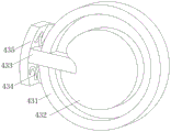
优选的,所述限位组件包括有安装壳,所述安装壳的表面与所述外接座的表面固定连接,所述安装壳的内壁上滑动连接有插杆,所述轴杆的一端固定连接有转盘,所述插杆的一端插接在所述转盘内,所述插杆的另一端贯穿所述安装壳并固定连接有拨动板,所述拨动板的表面通过复位弹簧与所述安装壳的表面弹性连接。Preferably, the limit assembly includes a mounting shell, the surface of the mounting shell is fixedly connected to the surface of the external seat, an insertion rod is slidably connected to the inner wall of the mounting shell, and one end of the shaft is fixedly connected There is a turntable, one end of the insertion rod is plugged into the turntable, the other end of the insertion rod passes through the installation shell and is fixedly connected with a toggle plate, the surface of the toggle plate is connected to the Surface elastic connection of mounting shells.
优选的,所述拾音头的顶部固定连接有挡板,所述挡板的顶部与所述转动框内部的顶壁接触,所述挡板的表面开设有凹槽。Preferably, a baffle is fixedly connected to the top of the pickup head, the top of the baffle is in contact with the top wall inside the rotating frame, and a groove is opened on the surface of the baffle.
借由上述技术方案,本发明提供了一种可定位式检查听诊设备。至少具备以下有益效果:By means of the above technical solution, the present invention provides a positionable examination and auscultation equipment. At least have the following beneficial effects:
(1)、该可定位式检查听诊设备,通过设置定位机构,能够将拾音头固定在患者皮肤上,使用时,医生只需头戴耳挂即可时刻关注患者脏器跳动的情况,无需用手紧握拾音头,便于医生腾出双手来对患者进行其它检查和治疗,使得医生在紧急治疗的同时也能时刻关注患者的脏器跳动情况,为抢救患者争取了宝贵的时间。(1) The positionable inspection and auscultation equipment can fix the pickup head on the patient's skin by setting a positioning mechanism. When in use, the doctor only needs to wear ear hooks to keep an eye on the beating of the patient's organs. Hold the pickup head tightly with your hands, so that the doctor can free up his hands to perform other examinations and treatments on the patient, so that the doctor can always pay attention to the beating of the patient's organs during emergency treatment, and win valuable time for rescuing the patient.
(2)、该可定位式检查听诊设备,通过设置调节机构,能够对定位机构中的拾音器进行位置调节,从而使得拾音头能够更加准确的拾取脏器处发出的声音,在调节的过程中,无需将定位机构从患者皮肤上取下,从而能够提高调节和听诊的效率,减少时间的浪费。(2), the positionable inspection and auscultation equipment, by setting the adjustment mechanism, can adjust the position of the pickup in the positioning mechanism, so that the pickup can pick up the sound from the viscera more accurately. , it is not necessary to remove the positioning mechanism from the patient's skin, thereby improving the efficiency of adjustment and auscultation, and reducing the waste of time.
(3)、该可定位式检查听诊设备,通过设置控制机构,能够控制定位机构内部的气体压强,并利用负压将固定框吸附在人体皮肤上,该控制机构在使用时,只需按压两个按压板即可,操作简单使用,有效避免了时间的浪费。(3) The positionable inspection and auscultation equipment can control the gas pressure inside the positioning mechanism by setting the control mechanism, and use the negative pressure to adsorb the fixed frame on the human skin. When the control mechanism is in use, it only needs to press two Only one pressing plate is enough, the operation is simple to use, and the waste of time is effectively avoided.
(4)、该可定位式检查听诊设备,通过设置限位组件,能够自动对轴杆进行限位,从而使得抽气塞不会因气压的改变而随意移动,保证了负压吸附的稳定性,本限位机构能够实现自动限位,无需手动进行操作,进一步减少了时间的消耗。(4) The positionable inspection and auscultation equipment can automatically limit the shaft rod by setting the limit component, so that the suction plug will not move randomly due to the change of air pressure, ensuring the stability of negative pressure adsorption , the limit mechanism can realize automatic limit without manual operation, further reducing time consumption.
附图说明Description of drawings
此处所说明的附图用来提供对本发明的进一步理解,构成本申请的一部分:The accompanying drawings described herein are used to provide a further understanding of the present invention and constitute a part of this application:
图1为本发明的整体结构示意图;Fig. 1 is the overall structure schematic diagram of the present invention;
图2为本发明的整体结构剖视图;Fig. 2 is a sectional view of the overall structure of the present invention;
图3为本发明中定位机构示意图;Fig. 3 is a schematic diagram of positioning mechanism in the present invention;
图4为本发明中控制机构示意图;Fig. 4 is a schematic diagram of a control mechanism in the present invention;
图5为本发明中涡卷弹簧示意图;Fig. 5 is a schematic diagram of a scroll spring in the present invention;
图6为本发明中限位组件示意图;Fig. 6 is a schematic diagram of the limiting assembly in the present invention;
图7为本发明中驱动块示意图;Fig. 7 is a schematic diagram of a drive block in the present invention;
图8为本发明中挡板示意图。Fig. 8 is a schematic diagram of the baffle in the present invention.
图中:1、拾音头;2、定位机构;21、固定框;22、衬垫;23、吸附口;24、抽气孔;25、连接腔;3、调节机构;31、转动框;32、第一磁块;33、磁环;34、第二磁块;35、连接杆;36、转扭;4、控制机构;41、外接座;42、连接孔;43、限位组件;431、安装壳;432、转盘;433、插杆;434、复位弹簧;435、拨动板;44、储气腔;45、抽气塞;46、驱动块;47、转柱;48、轴杆;49、齿轮;410、齿条;411、螺旋杆;412、限位杆;413、压板;414、通气孔;415、涡卷弹簧;5、挡板;6、凹槽;7、导音管。In the figure: 1. Pickup head; 2. Positioning mechanism; 21. Fixed frame; 22. Liner; 23. Adsorption port; 24. Air extraction hole; 25. Connecting cavity; , the first magnetic block; 33, the magnetic ring; 34, the second magnetic block; 35, the connecting rod; 36, the twist; 4, the control mechanism; 41, the external seat; 42, the connecting hole; 43, the limit assembly; 431 , mounting shell; 432, turntable; 433, inserting rod; 434, return spring; 435, toggle plate; 44, air storage cavity; 45, air extraction plug; 46, driving block; 47, rotating column; 48, shaft ; 49, gear; 410, rack; 411, screw rod; 412, limit rod; 413, pressure plate; 414, air hole; 415, scroll spring; 5, baffle plate; 6, groove; 7, sound guide Tube.
具体实施方式Detailed ways
下面将结合本发明实施例中的附图,对本发明实施例中的技术方案进行清楚、完整地描述,显然,所描述的实施例仅仅是本发明一部分实施例,而不是全部的实施例。基于本发明中的实施例,本领域普通技术人员在没有做出创造性劳动前提下所获得的所有其他实施例,都属于本发明保护的范围。The following will clearly and completely describe the technical solutions in the embodiments of the present invention with reference to the accompanying drawings in the embodiments of the present invention. Obviously, the described embodiments are only some, not all, embodiments of the present invention. Based on the embodiments of the present invention, all other embodiments obtained by persons of ordinary skill in the art without making creative efforts belong to the protection scope of the present invention.
请参阅图1-图8所示,本发明提供的一种技术方案:Please refer to Fig. 1-shown in Fig. 8, a kind of technical solution provided by the present invention:
一种可定位式检查听诊设备,包括拾音头1,也即听诊头,用于收集和放大从心脏、肺部、动脉、静脉和其他内脏器官处发出的声音,拾音头1上固定安装有导音管7,用以传递声音,导音管7远离拾音头1的一端固定连接有耳挂,用于听音。传统的听诊设备在使用时,需要医生头戴耳挂,并用一只手紧握听诊头,将听诊头放置在患者胸腔部位,来听取脏器处的声音,在整个听诊的过程中,医生的一只手无法离开听诊头,导致其无法兼顾其它治疗。本听诊设备设置有定位机构2,用以将拾音头1固定在人体皮肤上,因此,医生只需头戴耳挂即可时刻关注患者脏器跳动的情况,便于医生腾出双手去做其它事情;调节机构3,调节机构3设置在定位机构2与拾音头1之间,用以调节拾音头1的位置,使得拾音头1能够更加准确的拾取脏器处发出的声音;以及控制机构4,控制机构4设置在定位机构2上,用以控制定位机构2内部的气体压强,使得定位机构2底部能够产生负压,从而能够吸附在人体皮肤表面,控制机构4的数量为两个,两个控制机构4以固定框21的中心线为对称轴对称分布,使得其对气体抽取的效果更好。A positionable inspection and auscultation equipment, including a
本实施例中,定位机构2包括有固定框21,拾音头1位于固定框21内,固定框21的底部固定连接有衬垫22,拾音头1的底部与衬垫22的顶部接触,衬垫22由软性材料制成,使得拾音头1底部能够更好的与人体贴合,同时也使得拾音头1能够更清晰地拾取声音,固定框21的底部开设有四个吸附口23,四个吸附口23之间以固定框21的轴线为中心呈圆形阵列分布,为了提高吸附效果,吸附口23的数量也可设置更多,固定框21的内部开设有连接腔25,四个吸附口23均与连接腔25连通,固定框21的表面开设有抽气孔24,抽气孔24的一端与连接腔25连通。In the present embodiment, the
进一步的是,控制机构4包括有外接座41,外接座41的表面与固定框21的表面固定连接,外接座41的内部开设有储气腔44,储气腔44的内壁上活塞连接有两个抽气塞45,两个抽气塞45以外接座41的中心线为对称轴对称分布,当两个抽气塞45同时向外接座41两侧移动式,二者之间的空腔会增大,从而可将外部气体抽入到二者之间的空腔内,外接座41的靠近外接座41的一侧开设有连接孔42,连接孔42位于两个抽气塞45之间,连接孔42的一端与储气腔44连通,连接孔42的另一端与抽气孔24远离连接腔25的一端连通,从而可将连接腔25和吸附口23内的气体抽出,使得吸附口23内呈现负压环境,从而将固定框21吸附在人体皮肤上,外接座41的内壁转动连接有轴杆48,轴杆48的表面固定连接有转柱47,转柱47的表面固定连接有螺旋杆411,螺旋杆411的表面螺旋传动有驱动块46,外接座41的内壁上固定连接有限位杆412,驱动块46的内壁与限位杆412的表面滑动连接,驱动块46的表面与抽气塞45的内壁固定连接,如图7所述,驱动块46上开设有螺旋槽,该螺旋槽的形状与螺旋杆411吻合,当螺旋杆411转动时,由于驱动块46受到限位杆412的限位作用而无法转动,导致其会沿着转柱47的轴线方向移动,并带动抽气塞45在储气腔44内做活塞运动,实现抽气与送气,外接座41的表面开设有通气孔414,使得抽气塞45一侧的气体与外部连通,当抽气塞45做活塞运动时,能够将其一侧的气体排出装置外或抽入装置中,从而可减小其做活塞运动时的阻力,轴杆48的表面固定连接有齿轮49,齿轮49的表面啮合有齿条410,齿条410的表面与外接座41的内壁滑动连接,齿条410远离固定框21的一端固定连接有按压板413,按压板413的表面与外接座41的内壁滑动连接,向外接座41内推动按压板413,即可带动齿条410移动,齿条410通过啮合带动齿轮49转动,从而为轴杆48的转动提供动力,按压板413上固定连接有限位板,限位板的表面与外接座41的内壁滑动连接,从而可对按压板413进行支撑限位,使得按压板413的使用更加稳定,轴杆48的表面通过涡卷弹簧415与外接座41的内壁弹性连接,外接座41上设置有限位组件43,用以限制轴杆48的圆周运动,通过设置涡卷弹簧415,使得限位组件43对轴杆48的限位效果解除后,轴杆48能够在弹力下自动复位,并带动齿轮49、齿条410、转柱47、螺旋杆411、驱动块46和抽气塞45等一同复位。Further, the control mechanism 4 includes an
如图6所示,限位组件43包括有安装壳431,安装壳431的表面与外接座41的表面固定连接,安装壳431的内壁上滑动连接有插杆433,轴杆48的一端固定连接有转盘432,转盘432的表面开设有插槽,插杆433的一端插接在转盘432上的插槽内,该插槽的一侧边缘为弧面,且插杆433靠近该弧面的一侧也设置有弧面,从而可对转盘432的转动方向进行限制,当转盘432正向转动时,可通过两弧面将插杆433向一侧推动,实现自动让位的目的,当转盘432转动一周后,插杆433会自动进入到插槽中,同时也使得该转盘432无法反向转动,达到限位的目的,插杆433的另一端贯穿安装壳431并固定连接有拨动板435,拨动板435的表面通过复位弹簧434与安装壳431的表面弹性连接,通过向外拉动拨动板435,可带动插杆433向一侧移动,从而使得插杆433从插槽中脱离,以解除其对转盘432的限位效果,使得转盘432可以反向转动,从而使得轴杆48可实现复位。As shown in Figure 6, the
本实施例中,调节机构3包括有转动框31,转动框31转动安装在固定框21的内壁上,转动框31与固定框21之间可通过现有技术如轴承、限位环等进行限位,在此不做赘述,转动框31的内壁上固定连接有第一磁块32,转动框31的内壁上转动连接有第二磁块34,第一磁块32与第二磁块34以转动框31的中心线为对称轴呈对称分布,拾音头1的表面固定连接有磁环33,磁环33与第一磁块32相对的一侧磁极相反,且磁环33与第二磁块34相对的一面磁极相反,第二磁块34的顶部固定连接有连接杆35,连接杆35的顶端贯穿转动框31并固定连接有转扭36,通过转动转扭36,可带动连接杆35转动,从而使得第二磁块34转动,当第二磁块34转动一百八十度后,其与磁环33相对的一面磁性相反,即可对磁环33进行吸引,此时,通过转动转动框31,即可带动第二磁块34和磁环33一同转动,实现对拾音头1的位置进行调节的目的。In this embodiment, the
拾音头1的顶部固定连接有挡板5,挡板5的顶部与转动框31内部的顶壁接触,从而可对拾音头1进行限位,避免拾音头1发生倾斜,挡板5的表面开设有凹槽6,当拾音头1向第二磁块34一侧移动时,导音管7可以进入到凹槽6内,使得导音管7可以更好的随拾音头1一起移动。The top of
工作原理,在一些紧急情况下,如救护车中、事故现场治疗时、紧急检查时,医生可将固定框21放置于患者皮肤上,使得固定框21底部的衬垫22与皮肤贴紧,然后同时向内按压两个按压板413,按压板413在移动的过程中会同步带动齿条410移动,齿条410通过啮合带动齿轮49转动一周,齿轮49带动轴杆48转动一周,轴杆48同时带动两个转柱47转动,转柱47带动螺旋杆411转动,在螺旋杆411转动时,由于驱动块46受到限位杆412的限位作用而无法转动,导致其会沿着转柱47的轴线方向向外接座41外侧移动,并带动抽气塞45在储气腔44内做活塞运动,在这个过程中,两个抽气塞45之间的空腔会增大,从而可通过连接孔42和抽气孔24将连接腔25和吸附口23内的气体抽出,使得吸附口23内呈现负压环境,从而将固定框21吸附在人体皮肤上,此时,医生只需头戴耳挂即可时刻关注患者脏器跳动的情况,便于医生腾出双手去做其它事情,使得医生在紧急治疗的同时也能时刻关注患者的脏器跳动情况,若医生需要对拾音头1的位置进行调整时,可转动转扭36,使得转扭36带动连接杆35转动,连接杆35带动第二磁块34转动一百八十度后,其与磁环33相对的一面磁性相反,可对磁环33进行吸引,从而使得拾音头1吸附在转动框31上,此时通过转动转动框31,即可带动拾音头1转动,实现对拾音头1的位置进行调节的目的。Working principle, in some emergency situations, such as in an ambulance, during accident scene treatment, or emergency inspection, the doctor can place the fixed
需要说明的是,在本文中,诸如第一和第二等之类的关系术语仅仅用来将一个实体或者操作与另一个实体或操作区分开来,而不一定要求或者暗示这些实体或操作之间存在任何这种实际的关系或者顺序。而且,术语“包括”、“包含”或者其任何其他变体意在涵盖非排他性的包含,从而使得包括一系列要素的过程、方法、物品或者设备不仅包括那些要素,而且还包括没有明确列出的其他要素,或者是还包括为这种过程、方法、物品或者设备所固有的要素。It should be noted that in this article, relational terms such as first and second are only used to distinguish one entity or operation from another entity or operation, and do not necessarily require or imply that there is a relationship between these entities or operations. There is no such actual relationship or order between them. Furthermore, the term "comprises", "comprises" or any other variation thereof is intended to cover a non-exclusive inclusion such that a process, method, article, or apparatus comprising a set of elements includes not only those elements, but also includes elements not expressly listed. other elements of or also include elements inherent in such a process, method, article, or device.
尽管已经示出和描述了本发明的实施例,对于本领域的普通技术人员而言,可以理解在不脱离本发明的原理和精神的情况下可以对这些实施例进行多种变化、修改、替换和变型,本发明的范围由所附权利要求及其等同物限定。Although the embodiments of the present invention have been shown and described, those skilled in the art can understand that various changes, modifications and substitutions can be made to these embodiments without departing from the principle and spirit of the present invention. and modifications, the scope of the invention is defined by the appended claims and their equivalents.
Claims (9)
Priority Applications (1)
| Application Number | Priority Date | Filing Date | Title |
|---|---|---|---|
| CN202211500373.6A CN115969407A (en) | 2022-11-28 | 2022-11-28 | Positionable examination auscultation equipment |
Applications Claiming Priority (1)
| Application Number | Priority Date | Filing Date | Title |
|---|---|---|---|
| CN202211500373.6A CN115969407A (en) | 2022-11-28 | 2022-11-28 | Positionable examination auscultation equipment |
Publications (1)
| Publication Number | Publication Date |
|---|---|
| CN115969407A true CN115969407A (en) | 2023-04-18 |
Family
ID=85974813
Family Applications (1)
| Application Number | Title | Priority Date | Filing Date |
|---|---|---|---|
| CN202211500373.6A Withdrawn CN115969407A (en) | 2022-11-28 | 2022-11-28 | Positionable examination auscultation equipment |
Country Status (1)
| Country | Link |
|---|---|
| CN (1) | CN115969407A (en) |
Cited By (1)
| Publication number | Priority date | Publication date | Assignee | Title |
|---|---|---|---|---|
| CN121081007A (en) * | 2025-09-24 | 2025-12-09 | 首都医科大学附属首都儿童医学中心 | Wearable occlusion device bronchitis auscultation detector |
-
2022
- 2022-11-28 CN CN202211500373.6A patent/CN115969407A/en not_active Withdrawn
Cited By (2)
| Publication number | Priority date | Publication date | Assignee | Title |
|---|---|---|---|---|
| CN121081007A (en) * | 2025-09-24 | 2025-12-09 | 首都医科大学附属首都儿童医学中心 | Wearable occlusion device bronchitis auscultation detector |
| CN121081007B (en) * | 2025-09-24 | 2026-05-01 | 首都医科大学附属首都儿童医学中心 | Wearable occlusion device bronchitis auscultation detector |
Similar Documents
| Publication | Publication Date | Title |
|---|---|---|
| CN104720931B (en) | Imitative puborectalis formula dicyclo artificial anal sphincter prosthese | |
| CN204562463U (en) | There is the dicyclo artificial anal sphincter prosthese of pressure transducer | |
| CN109875483B (en) | Self-propelled capsule type gastroscope | |
| CN108784731A (en) | A kind of medical high adjustable stethoscope of pickup | |
| CN201098139Y (en) | Air-bone dual conduction stethoscope | |
| CN217696617U (en) | Sound amplifying structure for stethoscope | |
| CN219042729U (en) | Stethoscope capable of enlarging contact area of stethoscope head | |
| CN111134789A (en) | A kind of circumcision device for foreskin anastomosis for clinical use in urology | |
| CN211355559U (en) | A multifunctional stethoscope | |
| CN108078583A (en) | A kind of multi-functional noise-proofing stethoscope | |
| CN215349362U (en) | Nasal foreign body taking-out device | |
| CN215306047U (en) | Stethoscope for emergency internal medicine | |
| CN219782586U (en) | Pediatric stethoscope | |
| CN221511936U (en) | Assembled internal medicine physical examination stethoscope | |
| CN223490160U (en) | Breathe internal medicine with inhaling phlegm device | |
| CN207785172U (en) | Medical electronic stethoscope | |
| CN208388635U (en) | A kind of Medical stethoscope for emergency treatment | |
| CN222899157U (en) | Durable stethoscope | |
| CN219720637U (en) | Tongue depressor with built-in pressure sensing trigger type light source | |
| CN221903730U (en) | Intelligent diagnosis and treatment heart sound auscultation device | |
| CN219960701U (en) | Intensive care device based on internet of things | |
| CN221181175U (en) | A sputum suction device for nursing | |
| CN213309833U (en) | Stethoscope for pediatrics | |
| CN215078805U (en) | Multifunctional split stethoscope | |
| CN208625658U (en) | A kind of gastroenterology endoscope |
Legal Events
| Date | Code | Title | Description |
|---|---|---|---|
| PB01 | Publication | ||
| PB01 | Publication | ||
| SE01 | Entry into force of request for substantive examination | ||
| SE01 | Entry into force of request for substantive examination | ||
| WW01 | Invention patent application withdrawn after publication |
Application publication date: 20230418 |
|
| WW01 | Invention patent application withdrawn after publication |