CN115968180A - Air supply cabinet with multiple fans for heat dissipation - Google Patents
Air supply cabinet with multiple fans for heat dissipation Download PDFInfo
- Publication number
- CN115968180A CN115968180A CN202310140210.XA CN202310140210A CN115968180A CN 115968180 A CN115968180 A CN 115968180A CN 202310140210 A CN202310140210 A CN 202310140210A CN 115968180 A CN115968180 A CN 115968180A
- Authority
- CN
- China
- Prior art keywords
- cabinet
- control
- fan
- moving
- heat dissipation
- Prior art date
- Legal status (The legal status is an assumption and is not a legal conclusion. Google has not performed a legal analysis and makes no representation as to the accuracy of the status listed.)
- Pending
Links
- 230000017525 heat dissipation Effects 0.000 title claims abstract description 23
- 238000001816 cooling Methods 0.000 claims abstract description 20
- 238000009423 ventilation Methods 0.000 claims description 23
- 230000005540 biological transmission Effects 0.000 claims description 16
- 238000009434 installation Methods 0.000 claims description 5
- 230000004308 accommodation Effects 0.000 claims description 2
- 230000000694 effects Effects 0.000 abstract description 8
- 238000010586 diagram Methods 0.000 description 13
- 238000005516 engineering process Methods 0.000 description 2
- 230000009286 beneficial effect Effects 0.000 description 1
- 238000004891 communication Methods 0.000 description 1
- 238000007599 discharging Methods 0.000 description 1
- 230000007613 environmental effect Effects 0.000 description 1
- 238000000034 method Methods 0.000 description 1
- 230000006855 networking Effects 0.000 description 1
Images






Classifications
-
- Y—GENERAL TAGGING OF NEW TECHNOLOGICAL DEVELOPMENTS; GENERAL TAGGING OF CROSS-SECTIONAL TECHNOLOGIES SPANNING OVER SEVERAL SECTIONS OF THE IPC; TECHNICAL SUBJECTS COVERED BY FORMER USPC CROSS-REFERENCE ART COLLECTIONS [XRACs] AND DIGESTS
- Y02—TECHNOLOGIES OR APPLICATIONS FOR MITIGATION OR ADAPTATION AGAINST CLIMATE CHANGE
- Y02D—CLIMATE CHANGE MITIGATION TECHNOLOGIES IN INFORMATION AND COMMUNICATION TECHNOLOGIES [ICT], I.E. INFORMATION AND COMMUNICATION TECHNOLOGIES AIMING AT THE REDUCTION OF THEIR OWN ENERGY USE
- Y02D10/00—Energy efficient computing, e.g. low power processors, power management or thermal management
Landscapes
- Cooling Or The Like Of Electrical Apparatus (AREA)
Abstract
本发明涉及送风机柜领域,具体涉及一种多风扇散热的送风机柜,包括机柜,所述机柜内部下端四角处均设置有支撑板;机柜上端中心位置处具有的限位槽,限位槽内部滑动连接有旋转电机;所述旋转电机输出端与控制杆顶端固定连接;所述控制杆外侧从上至下依次设置有两组限位件、第一控制件和第二控制件;本发明通过移动服务器的位置从而增加各服务器间的间距,以使空气更易流通,从而增加散热效果;本发明通过在移动服务器位置的同时切换为不同的风扇对服务器进行散热,可在机柜内温度较低时通过散热风扇对服务器进行统一散热,以降低电量消耗,在机柜内温度较高时切换为高速旋转风扇对各服务器进行单独散热,从而增加散热效果。

The invention relates to the field of air supply cabinets, in particular to a multi-fan heat dissipation air supply cabinet, including a cabinet, support plates are arranged at the four corners of the lower end inside the cabinet; A rotating motor is slidingly connected inside; the output end of the rotating motor is fixedly connected to the top of the control rod; two sets of limiting parts, a first control part and a second control part are arranged on the outer side of the control rod in sequence from top to bottom; the present invention By moving the position of the server, the distance between the servers is increased, so that the air can circulate more easily, thereby increasing the heat dissipation effect; the present invention switches to different fans to dissipate heat from the server while moving the position of the server, so that the temperature in the cabinet can be lower When the temperature in the cabinet is high, the cooling fan is used to uniformly cool the servers to reduce power consumption. When the temperature in the cabinet is high, it is switched to a high-speed rotating fan to cool each server individually, thereby increasing the cooling effect.
Description
技术领域technical field
本发明涉及送风机柜领域,具体涉及一种多风扇散热的送风机柜。The invention relates to the field of air supply cabinets, in particular to an air supply cabinet with multiple fans for heat dissipation.
背景技术Background technique
随着计算机与网络技术的发展,机柜正成为其重要的组成部分。数据中心的服务器、网络通信设备等IT设施,正在向着小型化、网络化、机架化的方向发展,而机柜,正在逐渐成为这个变化中的主角之一。随着计算机计算技术的高速发展,服务器机柜已经成为计算机设备领域的标准配制,现已广泛应用于各行业、各领域中。由于服务器连续工作时间较长,需要在服务器机柜中设置风扇。风扇是控制机柜温度的重要环节,其用于避免由于机柜温度过高而造成的服务故障,同时达到节能环保的目的。With the development of computer and network technology, the cabinet is becoming an important part of it. IT facilities such as servers and network communication equipment in data centers are developing in the direction of miniaturization, networking, and racking, and cabinets are gradually becoming one of the protagonists in this change. With the rapid development of computer computing technology, server cabinets have become a standard configuration in the field of computer equipment, and have been widely used in various industries and fields. Since the server works continuously for a long time, it is necessary to install a fan in the server cabinet. The fan is an important part of controlling the temperature of the cabinet. It is used to avoid service failures caused by excessive cabinet temperature and achieve the purpose of energy saving and environmental protection.
发明内容Contents of the invention
因此,本发明正是鉴于以上问题而做出的,本发明的目的在于当机柜内温度过高时,通过在移动服务器位置的同时切换为高效散热风扇,以完成对各服务器的快速散热,本发明是通过以下技术方案实现上述目的:Therefore, the present invention is made in view of the above problems. The purpose of the present invention is to switch to a high-efficiency heat dissipation fan while moving the position of the server when the temperature in the cabinet is too high, so as to complete the rapid heat dissipation of each server. The invention realizes the above-mentioned purpose through the following technical solutions:
一种多风扇散热的送风机柜,包括机柜,其特征在于:所述机柜内部下端四角处均设置有支撑板;机柜上端中心位置处具有的限位槽,限位槽内部滑动连接有旋转电机;所述旋转电机输出端与控制杆顶端固定连接;所述控制杆外侧从上至下依次设置有两组限位件、第一控制件和第二控制件;所述第一控制件与第二控制件之间穿过有控制齿轮;所述控制齿轮与设置在机柜内部的安装板转动连接;所述控制齿轮上端中心处设置有第一控制槽;所述控制齿轮通过第一控制皮带驱动传动齿轮,传动齿轮通过第二控制皮带驱动驱动齿轮;所述传动齿轮和驱动齿轮下端均设置有高速旋转风扇;所述液压机构固定设置于安装板上端;所述安装板底部中心处可旋转安装有散热风扇;所述机柜内部下端四角处均设置有支撑板;服务器设备可滑动安装于四个支撑板上端。A blower cabinet with multiple fans for heat dissipation, including a cabinet, characterized in that: the four corners of the lower end of the cabinet are provided with support plates; the upper center of the cabinet has a limit slot, and the inside of the limit slot is slidably connected to a rotating motor ; The output end of the rotating motor is fixedly connected to the top of the control rod; two sets of limit parts, a first control part and a second control part are arranged on the outer side of the control rod in sequence from top to bottom; the first control part and the second control part A control gear passes through between the two control parts; the control gear is rotatably connected to the mounting plate arranged inside the cabinet; a first control groove is arranged at the center of the upper end of the control gear; the control gear is driven by the first control belt Transmission gear, the transmission gear drives the driving gear through the second control belt; the lower end of the transmission gear and the driving gear is provided with a high-speed rotating fan; the hydraulic mechanism is fixed on the top of the mounting plate; the center of the bottom of the mounting plate can be rotatably installed There are cooling fans; the four corners of the lower end of the cabinet are provided with support plates; the server equipment can be slidably installed on the top of the four support plates.
本发明有益效果:Beneficial effects of the present invention:
1、本发明通过移动服务器的位置从而增加各服务器间的间距,以使空气更易流通,从而增加散热效果;1. The present invention increases the distance between the servers by moving the positions of the servers, so that the air can circulate more easily, thereby increasing the heat dissipation effect;
2、本发明通过在移动服务器位置的同时切换为不同的风扇对服务器进行散热,可在机柜内温度较低时通过散热风扇对服务器进行统一散热,以降低电量消耗,在机柜内温度较高时切换为高速旋转风扇对各服务器进行单独散热,从而增加散热效果;2. The present invention switches to different fans to dissipate heat from the server while moving the position of the server. When the temperature in the cabinet is low, the cooling fan can be used to uniformly dissipate heat from the server to reduce power consumption. When the temperature in the cabinet is high Switch to a high-speed rotating fan to cool each server separately, thereby increasing the cooling effect;
3、本发明通过在移动服务器位置的同时可控制通风口的开关,以使当机柜在日常使用中关闭通风口,从而达到防水防尘的效果,并当机柜内温度较高时通风口打开以使空气更易流通,从而增加散热效果;3. The present invention can control the switch of the ventilation port while moving the position of the server, so that when the cabinet is in daily use, the ventilation port is closed, so as to achieve the effect of waterproof and dustproof, and when the temperature in the cabinet is high, the ventilation port is opened to Make the air flow more easily, thereby increasing the heat dissipation effect;
4、本发明通过在机柜内温度较高时控制中央风扇旋转,并通过中央风扇吹动机柜内的热气,并将热气通过通风口排出,从而增加散热效果。4. The present invention controls the rotation of the central fan when the temperature in the cabinet is high, blows the hot air in the cabinet through the central fan, and discharges the hot air through the vents, thereby increasing the cooling effect.
附图说明Description of drawings
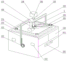
图1为本发明提供的整体结构示意图。Figure 1 is a schematic diagram of the overall structure provided by the present invention.
图2为本发明提供的机柜结构示意图。Fig. 2 is a schematic structural diagram of a cabinet provided by the present invention.
图3为本发明提供的机柜内部结构示意图。Fig. 3 is a schematic diagram of the internal structure of the cabinet provided by the present invention.
图4为本发明提供的整体内部结构示意图。Fig. 4 is a schematic diagram of the overall internal structure provided by the present invention.
图5为本发明提供的控制机构整体结构示意图。Fig. 5 is a schematic diagram of the overall structure of the control mechanism provided by the present invention.
图6为本发明提供的控制机构整体结构正视图。Fig. 6 is a front view of the overall structure of the control mechanism provided by the present invention.
图7为本发明提供的图5中A处结构放大图。Fig. 7 is an enlarged view of the structure at A in Fig. 5 provided by the present invention.
图8为本发明提供的控制杆结构示意图。Fig. 8 is a schematic structural diagram of the control rod provided by the present invention.
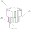
图9为本发明提供的传动齿轮结构示意图。Fig. 9 is a schematic structural diagram of the transmission gear provided by the present invention.
图10为本发明提供的高速旋转风扇结构示意图。Fig. 10 is a schematic structural diagram of the high-speed rotating fan provided by the present invention.
图11为本发明提供的散热风扇机构示意图。Fig. 11 is a schematic diagram of the cooling fan mechanism provided by the present invention.
图12为本发明提供的服务器设备整体结构示意图。FIG. 12 is a schematic diagram of the overall structure of the server device provided by the present invention.
图13为本发明提供的支撑板结构示意图。Fig. 13 is a schematic structural diagram of the support plate provided by the present invention.
图14为本发明提供的单个服务器设备结构示意图。Fig. 14 is a schematic structural diagram of a single server device provided by the present invention.
图15为本发明提供的移动件结构示意图。Fig. 15 is a schematic structural diagram of the moving part provided by the present invention.
图16为本发明提供的中央风扇结构示意图。Fig. 16 is a schematic structural view of the central fan provided by the present invention.
附图标记说明:Explanation of reference signs:
图中,100、机柜;101、第一通风部;102、容纳部;103、第二通风部;104、滑动槽;105、安装槽;106、限位槽;107、导向件;110、支撑板;111、第一移动槽;120、安装板;130、柜门;200、旋转电机;300、控制杆;310、限位件;320、第一控制件;330、第二控制件;340、控制齿轮;341、第一控制槽;350、第一控制皮带;360、传动齿轮;361、驱动部;362、安装部;370、驱动齿轮;380、第二控制皮带;400、液压机构;410、控制板;411、控制部;412、旋转齿轮;500、散热风扇;501、第二控制槽;510、高速旋转风扇;600、服务器设备;601、第一移动部;602、第二移动部;610、移动件;611、移动杆;612、第二移动槽;613、第一通风件;614、第二通风件;620、中央风扇;621、风扇叶片;622、抵合槽;623、第三控制槽。In the figure, 100, cabinet; 101, first ventilation part; 102, accommodation part; 103, second ventilation part; 104, sliding groove; 105, installation groove; 106, limit groove; 107, guide piece; 110,
具体实施方式Detailed ways
本发明优选实施例将通过参考附图进行详细描述然而本发明也可以各种不同的形式实现,因此本发明不限于下文中描述的实施例,另外,为了更清楚地描述本发明,与发明没有连接的部件将从附图中省略;Preferred embodiments of the present invention will be described in detail with reference to the accompanying drawings, but the present invention can also be implemented in various forms, so the present invention is not limited to the embodiments described hereinafter. In addition, in order to describe the present invention more clearly, there is no Connected parts will be omitted from the drawings;
如图1-4所示,一种多风扇散热的送风机柜包括:用于支撑与装载内部装置的机柜100,位于机柜100内部下端的支撑板110,位于机柜100内部上端的安装板120,位于机构100上端中心位置处的旋转电机200,位于旋转电机200下端的控制杆300,位于安装板120上端的液压机构400,位于安装板120下端的散热风扇500,位于支撑板110上端的服务器设备600;As shown in Figures 1-4, a multi-fan cooling fan cabinet includes: a
所述机柜100内部下端四角处均设置有支撑板110;
所述机柜100的左右两侧外端设置有柜门130;
所述四个支撑板110上端均设置有服务器设备600;The upper ends of the four
所述服务器设备600由服务器和壳体构成,且服务器位于壳体内部;The
如图1-9所示,所述旋转电机200可滑动安装于机柜100上端中心位置处具有的限位槽106中;As shown in Figures 1-9, the rotating
所述旋转电机200可沿机柜100上端下侧设置的导向件107上下滑动;The rotating
所述旋转电机200输出端与控制杆300顶端固定连接;The output end of the rotating
所述控制杆300上端设置有两组限位件310;The upper end of the
所述限位件310下端设置有第一控制件320;The lower end of the limiting
所述第一控制件320下端设置有第二控制件330;The lower end of the
如图5和图7所示,所述第一控制件320与第二控制件330之间穿过有控制齿轮340;所述控制齿轮340与设置在机柜100内部的安装板120转动连接;As shown in FIGS. 5 and 7 , a
所述控制齿轮340上端中心处设置有第一控制槽341;A
所述第一控制槽341与第一控制件320形状相同;The
所述控制齿轮340外侧安装有第一控制皮带350,且第一控制皮带350另一端安装在传动齿轮360外侧;A
所述传动齿轮360下端设置有驱动部361;The lower end of the
所述驱动部361下端设置有安装部362;The lower end of the driving
所述传动齿轮360通过安装部362可旋转安装于安装板120上端;The
所述驱动部361位于安装板120上端一角处,且安装板120上端其余三角处均可旋转安装有驱动齿轮370;The driving
所述驱动部361与驱动齿轮370外侧安装有第二控制皮带380;A
所述液压机构400固定设置于安装板120上端;The
所述液压机构400输出端与控制板410下端固定连接;The output end of the
所述控制板410可旋转安装于两组限位件310之间;The
所述控制板410前后两端均设置有控制部411;The front and rear ends of the
所述控制部411可沿机柜100前后两端具有的滑动槽104上下移动;The
所述控制部411下端一侧设置有齿牙,并与位于机柜100外侧下端可旋转安装的旋转齿轮412啮合;The lower end of the
如图10、图11所示,所述安装板120底部中心处可旋转安装有散热风扇500;As shown in Fig. 10 and Fig. 11, a cooling
所述散热风扇500下端中心处具有第二控制槽501;There is a
所述散热风扇500四周均设置有高速旋转风扇510;The
所述高速旋转风扇510可旋转安装于安装板120下端;The high-
所述高速旋转风扇510上端与安装部362和驱动齿轮370下端固定连接;The upper end of the high-
当通过旋转电机200控制控制齿轮340、第一控制皮带350、传动齿轮360、驱动部361带动高速旋转风扇510旋转时,高速旋转风扇510具有相较于散热风扇500较大的旋转速度;When the
如图1-16所示,所述四个服务器设备600均可滑动安装于四个支撑板110上端;As shown in Figure 1-16, the four
所述四个服务器设备600两两为一组分为两组;The four
所述同一组的服务器设备600远离机柜100中心位置且相互靠近的一端均设置有第二移动部602;The ends of the
所述服务器设备600下端中心处均设置有第一移动部601;A first moving
所述第一移动部601安装于支撑板110上端具有的第一移动槽111中,并可与其配合移动;The first moving
所述服务器设备600前后两侧滑动安装有移动件610;The front and rear sides of the
所述移动件610远离服务器设备600一端中心处设置有移动杆611;A moving
所述移动杆611外侧设置有螺纹且穿过机柜100前后两端下侧具有的安装槽105并与旋转齿轮412螺纹配合;The outer side of the moving
所述移动件610靠近服务器设备600一端中心处设置有第二移动槽612;A second moving
所述第二移动部602可滑动安装于第二移动槽612中;The second moving
所述移动件610靠近服务器设备600一侧前后两端均设置有第一通风件613;The front and rear ends of the moving
所述第一通风件613位置与机柜100左右两侧具有的第一通风部101位置对应,且可与其相对移动;The position of the
所述移动件610远离服务器设备600上侧两端均设置有第二通风件614;The moving
所述第二通风件614与机柜100前后两端具有的第二通风部103位置对应,且可与其相对移动;The
当所述移动件610带动服务器设备600移动至高速旋转风扇510下端时,移动件610位于机柜100内部左右两端具有的容纳部102中;When the moving
所述机柜100内部底端中心位置可旋转设置有中央风扇620;A
所述中央风扇620四周设置有风扇叶片621;
所述相邻的风扇叶片621之间设置有抵合槽622;A resisting
所述抵合槽622可供服务器设备600一角插入,以防止当散热风扇500旋转时产生气流导致中央风扇620转动;The abutting
所述中央风扇620上端设置有第三控制槽623;The upper end of the
所述第三控制槽623形状与第二控制件330形状相同;The shape of the
工作原理:working principle:
当需对机柜100内部进行高效散热时:通过液压机构400控制控制板410下降,从而控制旋转电机200沿导向件107向下移动,以使控制杆300下降,直至第一控制件320移动至第一控制槽341中、第二控制件330移动至第三控制槽623中,且在控制板410下降的同时控制部411控制旋转齿轮412旋转,从而带动移动件610向远离机柜100中心方向移动,并使四个服务器设备600沿第一移动槽111向机柜100四角处移动,直到移动至高速旋转风扇510下端,并带动第一通风部101与第二通风部103打开,随后控制旋转电机200驱动控制杆300旋转,从而通过控制齿轮340、第一控制皮带350、传动齿轮360、驱动部361带动高速旋转风扇510高速旋转,并控制中央风扇620旋转,从而将机柜100内部热气排出,从而达到散热的效果。When it is necessary to efficiently dissipate heat inside the cabinet 100: the
当需对机柜100内部进行普通散热时:控制旋转电机200停止,并通过液压机构400控制控制板410上升,直至第二控制件330移动至第二控制槽501中,且在控制板410上升的同时控制部411控制旋转齿轮412反转,从而带动移动件610向靠近机柜100中心方向移动,并使四个服务器设备600沿第一移动槽111向机柜100中心处移动,直到移动至散热风扇500下端,并带动第一通风部101与第二通风部103关闭,以在保证机柜100防尘防水功能的同时降低机柜100散热所消耗的能源。When it is necessary to perform ordinary heat dissipation inside the cabinet 100: control the
Claims (10)
Priority Applications (1)
| Application Number | Priority Date | Filing Date | Title |
|---|---|---|---|
| CN202310140210.XA CN115968180A (en) | 2023-02-21 | 2023-02-21 | Air supply cabinet with multiple fans for heat dissipation |
Applications Claiming Priority (1)
| Application Number | Priority Date | Filing Date | Title |
|---|---|---|---|
| CN202310140210.XA CN115968180A (en) | 2023-02-21 | 2023-02-21 | Air supply cabinet with multiple fans for heat dissipation |
Publications (1)
| Publication Number | Publication Date |
|---|---|
| CN115968180A true CN115968180A (en) | 2023-04-14 |
Family
ID=87358613
Family Applications (1)
| Application Number | Title | Priority Date | Filing Date |
|---|---|---|---|
| CN202310140210.XA Pending CN115968180A (en) | 2023-02-21 | 2023-02-21 | Air supply cabinet with multiple fans for heat dissipation |
Country Status (1)
| Country | Link |
|---|---|
| CN (1) | CN115968180A (en) |
Cited By (1)
| Publication number | Priority date | Publication date | Assignee | Title |
|---|---|---|---|---|
| CN117979540A (en) * | 2024-03-29 | 2024-05-03 | 国网江苏省电力有限公司泰州供电分公司 | A current converter and its distribution current control system |
-
2023
- 2023-02-21 CN CN202310140210.XA patent/CN115968180A/en active Pending
Cited By (1)
| Publication number | Priority date | Publication date | Assignee | Title |
|---|---|---|---|---|
| CN117979540A (en) * | 2024-03-29 | 2024-05-03 | 国网江苏省电力有限公司泰州供电分公司 | A current converter and its distribution current control system |
Similar Documents
| Publication | Publication Date | Title |
|---|---|---|
| CN113655860B (en) | Heat dissipation machine case and server | |
| CN103840383A (en) | Novel louver used for power distribution cabinet | |
| CN207976827U (en) | The computer cabinet of good heat dissipation effect | |
| CN220139342U (en) | Heat dissipation shell of series excited machine | |
| CN215452299U (en) | Explosion-proof switch cabinet with heat radiation structure | |
| CN211790355U (en) | Low-voltage switch cabinet of long-term high reliable operation | |
| CN104750211A (en) | Data center | |
| CN209994501U (en) | Fixing frame convenient for switch stacking and placing | |
| CN221281501U (en) | Server with air guide structure | |
| CN221103903U (en) | Auxiliary heat dissipation device for network server cabinet | |
| CN216699264U (en) | A switchgear with cooling and radiating device | |
| CN218095100U (en) | Auxiliary cooling device for desktop computer case | |
| CN206411579U (en) | The server of casing and the application casing | |
| CN211792608U (en) | Anti-interference equipment for electronic information | |
| CN217305296U (en) | Electric power metering box with anti-electricity-stealing function | |
| CN211702848U (en) | Computer lab switch board that radiating effect is excellent | |
| CN214945175U (en) | A heat dissipation mounting frame based on the control structure of an air conditioner computer board | |
| CN210327422U (en) | Low pressure variable frequency control cabinet with two heat radiation structure | |
| CN109582107B (en) | Computer diversion cooling heat dissipation mechanism | |
| CN219041078U (en) | Heat abstractor for be used for high low voltage electrical equipment complete sets | |
| CN222366508U (en) | Radiator fan structure | |
| CN221979429U (en) | An electric heating control cabinet for crude oil pipeline | |
| CN207488927U (en) | A kind of computer heat radiating device mounted on computer cabinet | |
| CN224192300U (en) | A cooling device for high-voltage frequency converter cabinets | |
| CN221042119U (en) | Partition isolation type locomotive electric comprehensive control cabinet |
Legal Events
| Date | Code | Title | Description |
|---|---|---|---|
| PB01 | Publication | ||
| PB01 | Publication | ||
| SE01 | Entry into force of request for substantive examination | ||
| SE01 | Entry into force of request for substantive examination | ||
| WD01 | Invention patent application deemed withdrawn after publication | ||
| WD01 | Invention patent application deemed withdrawn after publication |
Application publication date: 20230414 |