CN115962752B - Measuring method and measuring equipment for horizontal rotation angle of inclinometer tube - Google Patents
Measuring method and measuring equipment for horizontal rotation angle of inclinometer tube Download PDFInfo
- Publication number
- CN115962752B CN115962752B CN202310250423.8A CN202310250423A CN115962752B CN 115962752 B CN115962752 B CN 115962752B CN 202310250423 A CN202310250423 A CN 202310250423A CN 115962752 B CN115962752 B CN 115962752B
- Authority
- CN
- China
- Prior art keywords
- angle
- axis
- rotation angle
- angle sensor
- inclinometer
- Prior art date
- Legal status (The legal status is an assumption and is not a legal conclusion. Google has not performed a legal analysis and makes no representation as to the accuracy of the status listed.)
- Active
Links
Images

Landscapes
- Length Measuring Devices With Unspecified Measuring Means (AREA)
Abstract
The embodiment of the application relates to the technical field of engineering monitoring and discloses a measuring method and measuring equipment for a horizontal rotation angle of an inclinometer. The measuring method comprises the steps of placing an angle sensor in an inclinometer pipe, and enabling the angle sensor to move up and down in the inclinometer pipe; when the angle sensor reaches a detection position in the inclinometer pipe, respectively acquiring a first inclination angle alpha of the inclinometer pipe relative to the horizontal plane of the foundation pit along the X-axis direction, a second inclination angle beta of the inclinometer pipe relative to the horizontal plane of the foundation pit along the Y-axis direction and a rotation angle gamma of the inclinometer pipe around the Z-axis direction by the angle sensor; and sending the collected angle data to a controller. According to the measuring method and the measuring equipment for the horizontal rotation angle of the inclinometer pipe, the posture of the inclinometer pipe can be obtained more accurately.
Description
Technical Field
The embodiment of the application relates to the technical field of engineering monitoring, in particular to a measuring method and measuring equipment for a horizontal rotation angle of an inclinometer.
Background
With the rapid development of the economic society, various infrastructure construction is increasing. In the construction process, foundation pit construction is an important project. In the foundation pit construction process, the horizontal displacement of the soil body needs to be monitored to determine the safety risk of the foundation pit. The inclinometry technology is a main technology for monitoring the horizontal displacement of the soil body, and in the application process of the inclinometry technology, an inclinometry pipe can be buried, and the purpose of monitoring the deformation of the soil body is finally achieved by measuring the state data of different positions in the inclinometry pipe.
The state data of the inclinometer pipe can be obtained by measuring the posture of the inclinometer pipe. Pose refers to the relationship between a reference coordinate system and a body coordinate system, and is generally characterized by three angles, namely a pitch angle, a roll angle and a yaw angle, and is generally called as a pose angle. The pitch angle represents the included angle between the X axis of the machine body and the horizontal plane; the roll angle represents the included angle between the Y axis of the machine body and the horizontal plane; yaw angle means the angle between the projection of the body X-axis to the horizontal plane and the reference system X-axis, also called horizontal rotation angle.
Because the inclinometer pipe can relatively twist between the upper section and the lower section in the binding construction process, the monitoring precision can be reduced after the inclinometer pipe is twisted, and therefore the posture of the inclinometer pipe cannot be accurately obtained.
Disclosure of Invention
An object of the embodiments of the present application is to provide a measuring method and a measuring device for a horizontal rotation angle of an inclinometer pipe, which can more accurately obtain the posture of the inclinometer pipe.
In order to solve the above technical problems, embodiments of the present application provide a method for measuring a horizontal rotation angle of an inclinometer pipe, including:
placing an angle sensor in the inclinometer pipe, and enabling the angle sensor to move up and down in the inclinometer pipe;
when the angle sensor reaches a detection position in the inclinometer pipe, respectively acquiring a first inclination angle alpha of the inclinometer pipe relative to the horizontal plane of the foundation pit along the X-axis direction, a second inclination angle beta of the inclinometer pipe relative to the horizontal plane of the foundation pit along the Y-axis direction and a rotation angle gamma of the inclinometer pipe around the Z-axis direction by the angle sensor;
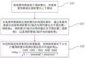
the collected angle data is sent to a controller, and the controller calculates the horizontal rotation angle of the inclinometer pipe at the detection position according to the following formula :

The X axis, the Y axis and the Z axis are perpendicular to each other, the X axis, the Y axis and the Z axis are all coordinate axes of a self coordinate system of the angle sensor, the horizontal plane of the foundation pit is a plane perpendicular to the gravity direction, and the horizontal rotation angle is an included angle formed by projection lines of two side lines forming the rotation angle in the horizontal plane of the foundation pit.
The embodiment of the application also provides measuring equipment, which comprises a shell, an angle sensor, a cable and a controller. The shell is provided with a containing cavity; the angle sensor is arranged in the accommodating cavity; one end of the cable is positioned in the accommodating cavity and is electrically connected with the angle sensor, and the other end of the cable extends out of the shell; the controller is electrically connected with the other end of the cable.
According to the measuring method and the measuring device for the horizontal rotation angle of the inclinometer pipe, the horizontal rotation angle of the inclinometer pipe at the corresponding detection position can be calculated by simultaneously measuring the inclination angles of the inclinometer pipe in the two directions perpendicular to each other and the rotation angle of the inclinometer pipe. Therefore, the measurement result can accurately reflect the distortion degree of the position of the inclinometer tube corresponding to the detection position, and the posture of the inclinometer tube can be obtained more accurately. So that an accurate measurement result can be finally obtained to reflect the horizontal displacement amount of the inclinometer pipe.
In some embodiments, before the angle sensor is placed in the inclinometer pipe, the method further comprises the steps of enabling an X axis in a coordinate system of the angle sensor to be perpendicular to the side face of the foundation pit, and enabling the angle sensor to be subjected to rotation angle zeroing.
In some embodiments, the plurality of detection positions in the inclinometer tube are arranged, and the adjacent two detection positions are separated by a preset distance.
In some embodiments, the angle sensor comprises two single axis tilt sensors arranged vertically, one single axis tilt sensor arranged towards the X-axis to acquire a first tilt angle, and the other single axis tilt sensor arranged towards the Y-axis to acquire a second tilt angle, and one rotation angle sensor to acquire a rotation angle.
In some embodiments, the angle sensor includes a dual-axis tilt sensor that respectively acquires the first tilt angle and the second tilt angle along different directions, and a rotation angle sensor that acquires the rotation angle.
In some embodiments, the angle sensor is a three-axis angle sensor that respectively acquires the first inclination angle, the second inclination angle, and the rotation angle along different directions.
Drawings
One or more embodiments are illustrated by way of example and not limitation in the figures of the accompanying drawings, in which like references indicate similar elements, and in which the figures of the drawings are not to be taken in a limiting sense, unless otherwise indicated.
FIG. 1 is a flow chart of a method for measuring the horizontal rotation angle of a inclinometer pipe provided in some embodiments of the present application;
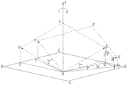
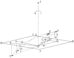
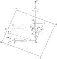
FIG. 2 is a schematic diagram of the front and rear position states of an angle sensor provided in some embodiments of the present application as it rotates in one instance;
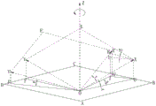
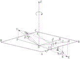
FIG. 3 is a schematic view of the front and rear position states of an angle sensor provided in some embodiments of the present application when rotated in another situation;
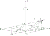
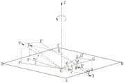
FIG. 4 is a schematic view of the front and rear position states of an angle sensor provided in some embodiments of the present application when rotated in yet another situation;
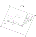
FIG. 5 is a schematic view of the front and rear position states of an angle sensor provided in some embodiments of the present application when rotated in yet another situation;
FIG. 6 is a schematic view of the front and rear position states of the angle sensor provided in some embodiments of the present application when rotated in yet another situation;
FIG. 7 is a schematic view of the front and rear position states of an angle sensor provided in some embodiments of the present application when rotated in yet another situation;
FIG. 8 is a schematic view of the front and rear position states of an angle sensor provided in some embodiments of the present application when rotated in yet another situation;
FIG. 9 is a schematic diagram of the front and rear position states of the angle sensor provided in some embodiments of the present application when rotated in yet another situation;
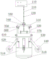
FIG. 10 is a schematic structural view of a measurement device provided in some embodiments of the present application;
FIG. 11 is a schematic view of a housing portion of a measurement device provided in some embodiments of the present application when positioned within an inclinometer pipe.
Detailed Description
For the purposes of making the objects, technical solutions and advantages of the embodiments of the present application more apparent, the following detailed description of each embodiment of the present application will be given with reference to the accompanying drawings. However, those of ordinary skill in the art will understand that in various embodiments of the present application, numerous technical details have been set forth in order to provide a better understanding of the present application. However, the technical solutions claimed in the present application can be implemented without these technical details and with various changes and modifications based on the following embodiments. The following embodiments are divided for convenience of description, and should not be construed as limiting the specific implementation of the present application, and the embodiments may be mutually combined and referred to without contradiction.
Unless defined otherwise, all technical and scientific terms used herein have the same meaning as commonly understood by one of ordinary skill in the art to which this application belongs; the terminology used herein is for the purpose of describing particular embodiments only and is not intended to be limiting of the application; the terms "comprising" and "having" and any variations thereof in the description and claims of the present application and in the description of the figures above are intended to cover non-exclusive inclusions.
In the description of the embodiments of the present application, the technical terms "first," "second," etc. are used merely to distinguish between different objects and are not to be construed as indicating or implying a relative importance or implicitly indicating the number of technical features indicated, a particular order or a primary or secondary relationship. In the description of the embodiments of the present application, the meaning of "plurality" is two or more unless explicitly defined otherwise.
In the description of the embodiments of the present application, unless explicitly specified and limited otherwise, the terms "mounted," "connected," "coupled," and the like should be construed broadly and may be, for example, fixedly connected, detachably connected, or integrally formed; or may be mechanically or electrically connected; can be directly connected or indirectly connected through an intermediate medium, and can be communicated with the inside of two elements or the interaction relationship of the two elements. The specific meaning of the above terms in the embodiments of the present application will be understood by those of ordinary skill in the art according to the specific circumstances.
The inclinometry technology is commonly used in deformation monitoring of foundation pit soil body, and plays a very critical role in early warning of safety risk of the foundation pit. When the inclinometer technology is applied, firstly, an inclinometer pipe is buried in soil body at a monitoring position, and then the inclinometer instrument is placed in the inclinometer pipe to measure the inclinometer pipe section by section.
The inclinometer is moved along a guide slot in the inclinometer tube during the measurement. Meanwhile, the detection direction of the inclinometer can be limited through the guide groove in the inclinometer.
However, the upper section and the lower section of the inclinometer tube are easy to twist during binding construction, and at this time, the guide grooves in the inclinometer tube are also twisted, so that the directions of the guide grooves at different positions are inconsistent. The extending direction of the guide groove deviates from the original straight line, and a horizontal rotation angle is generated on the horizontal surface of the foundation pit. When the horizontal rotation angle is generated, the included angle is positioned in different measurement planes in the whole measurement process, so that errors can occur in the included angle applied in calculation, and further, the inclination measurement data cannot truly reflect the deformation of the soil body. That is, when the measurement is performed in the twisted inclinometer pipe, the measurement result cannot effectively reflect the actual horizontal displacement amount of the foundation pit, and thus the safety risk of the foundation pit cannot be accurately known.
Even if the measurement of the rotation angle is added, the measurement result of the rotation angle cannot reflect the actual magnitude of the horizontal rotation angle of the inclinometer due to the defect of the existing detection mode.
Typically, the attitude angle of an object is measured with accelerometers, magnetometers, and gyroscopes.
The accelerometer can calculate the inclination angle of the object with respect to the horizontal plane by measuring the acceleration due to gravity. However, since the horizontal rotation angle is defined as the angle between the body coordinate system X-axis projected to the horizontal plane and the reference system X-axis, and the gravitational acceleration is exactly orthogonal to the horizontal plane, the accelerometer cannot measure the horizontal rotation angle.
The magnetometer is also called geomagnetism and a magnetic sensor, can be used for measuring the intensity and the direction of a magnetic field, and can calculate the horizontal rotation angle by combining the inclination angle of the X axis and the Y axis measured by the accelerometer and the triaxial magnetic component of the magnetometer, however, the magnetometer can cause larger errors due to surrounding ferromagnetic materials.
The angular motion detector is also called as a gyroscope, and is made by using the relative inertia space of a momentum moment sensitive shell of a high-speed revolving body around one or two axes orthogonal to a rotation shaft. However, the triaxial angle measured by the gyroscope chip is an angle between X, Y axis and horizontal plane, and the rotation angle using the Z axis as axis, so that only the angle measured when the gyroscope chip is horizontal is a horizontal rotation angle, and when the gyroscope is inclined, the measured rotation angle is deviated from the horizontal rotation angle.
Therefore, when the inclinometry technology is applied, how to measure the horizontal rotation angles at different positions of the inclinometer pipe plays an important role in the accuracy of the measurement result of the horizontal displacement of the inclinometer pipe.
In order to achieve accurate measurement of a horizontal rotation angle, some embodiments of the present application provide a method for measuring a horizontal rotation angle of an inclinometer. According to the measuring method, the inclination angles of the inclinometer pipe at the detection position in two vertical directions and the rotation angle of the inclinometer pipe at the detection position are collected, and then the horizontal rotation angle of the inclinometer pipe at the detection position is calculated through a formula. This makes it possible to select the angle sensor for different angles in the actual measurement without the angle measurement being affected by the type of sensor used. And substituting the angle data acquired by each angle sensor into a calculation formula to finally obtain accurate horizontal rotation angle data.
The following describes a method for measuring a horizontal rotation angle of an inclinometer pipe according to some embodiments of the present application with reference to fig. 1.
As shown in fig. 1, a method for measuring a horizontal rotation angle of an inclinometer pipe according to some embodiments of the present application includes the following steps:
step S10: the angle sensor is placed in the inclinometer pipe and is made to move up and down in the inclinometer pipe.
The angle sensor is used for collecting angle information and sending the collected angle information to a control center at the rear end for processing. In practice, the type of angle sensor includes, but is not limited to, a gyroscope, and any combination of sensor chips that can measure the inclination angle and the rotation angle of two axes.
Step S20: when the angle sensor reaches the detection position in the inclinometer, a first inclination angle alpha of the inclinometer relative to the horizontal plane of the foundation pit along the X-axis direction, a second inclination angle beta of the inclinometer relative to the horizontal plane of the foundation pit along the Y-axis direction and a rotation angle gamma of the inclinometer around the Z-axis direction are respectively acquired by the angle sensor.
The X axis, the Y axis and the Z axis are perpendicular to each other, and the X axis, the Y axis and the Z axis are all coordinate axes of a coordinate system of the angle sensor, and the foundation pit horizontal plane is a plane perpendicular to the gravity direction.
Step S30: the collected angle data is sent to a controller, and the controller calculates the horizontal rotation angle of the inclinometer pipe at the detection position according to the following formula :

The horizontal rotation angle is an included angle formed by projection lines of two side lines forming the rotation angle in the horizontal plane of the foundation pit.
In this way, according to the measuring method for the horizontal rotation angle of the inclinometer provided by some embodiments of the present application, the horizontal rotation angle of the inclinometer at the corresponding detection position of the inclinometer can be calculated by simultaneously measuring the inclination angles of the inclinometer in two directions perpendicular to each other and the rotation angle of the inclinometer. Therefore, the measurement result can accurately reflect the distortion degree of the position of the inclinometer tube corresponding to the detection position, and the posture of the inclinometer tube can be obtained more accurately. So that an accurate measurement result can be finally obtained to reflect the horizontal displacement amount of the inclinometer pipe.
The sources of the above formulas are described below in different types of practical cases:
fig. 2 shows a front-rear position state in which the angle sensor has a positive X-axis inclination angle and a positive Y-axis inclination angle, and the angle sensor rotates clockwise around the Z-axis (the clockwise rotation around the Z-axis is made positive and the counterclockwise rotation is made negative). In the figure, the plane ABCD is the foundation pit level. The plane OXEY is a coordinate plane of the initial position of the angle sensor. Vector quantity ,
 The directions of the angle sensor are the directions of the X axis and the Y axis respectively.
The angle XOX' is the angle around the Z-axis rotation angle acquired by the angle sensor, namely gamma.
OG and OF are projection lines OF OX and OY on the foundation pit horizontal plane ABCD respectively, and XG T OG and YF T OF are respectively formed.
OG ', OF ' are projection lines OF OX ', OY ', Y ' F ' OF ', respectively, on the foundation pit level ABCD.
The angle GOG' is the horizontal rotation angle of the angle sensor on the foundation pit horizontal plane ABCD, namely 。
The angle X 'OG' and the angle Y 'OF' are respectively the inclination angles OF the angle sensor in the X-axis direction and the Y-axis direction acquired after the angle sensor rotates around the Z axis, the angle X 'OG' is alpha, and the angle Y 'OF' is beta.
And crossing the X point to form an auxiliary line perpendicular to the OX ', and crossing the X point to form the XH T OX'.
GJ is the projection line of XH on the foundation pit level ABCD, HJ+.OG'.
According to XH 'O, OY' O 'and XH and OY' are both on the plane O 'E' Y ', then GJ' O.
And (3) taking the H point as an auxiliary line perpendicular to the XG, and intersecting the H point at the I point, so that the HI is T XG.
And obtaining HI/GJ according to XG/OG, HJ/OG' and HI/XG.
So +.XHI is equal to +.Y 'OF', i.e. β 1 =β。
Alpha, beta and gamma acquired by known angle sensors need to be calculated to obtain horizontal rotation angles . According to the cosine law:

and in Delta OHJ
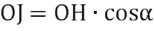
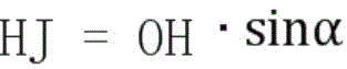
In ΔXHI


In Delta OXH
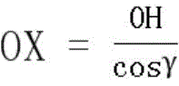
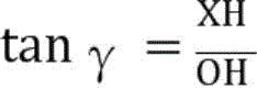
In Delta OXG



Bringing equations (2) through (10) into equation (1) yields:

fig. 3 shows a front-rear position state when the angle sensor is rotated counterclockwise about the Z axis, in which the angle sensor has a positive X-axis inclination angle and a positive Y-axis inclination angle. According to the same method as that described above, when the angle sensor is positive in the X-axis inclination angle and positive in the Y-axis inclination angle, and rotates counterclockwise around the Z-axis, the horizontal rotation angle calculation formula is calculated:

in case three, fig. 4 shows a front-rear position state when the angle sensor is rotated clockwise around the Z axis, in which the angle sensor X-axis inclination angle is positive and the Y-axis inclination angle is negative. According to the same method as that described above, when the angle sensor is positive in the X-axis inclination angle and negative in the Y-axis inclination angle, and rotates clockwise around the Z-axis, the horizontal rotation angle calculation formula is calculated:

fig. 5 shows a front-rear position state when the angle sensor rotates counterclockwise about the Z axis, in which the angle sensor has a positive X-axis inclination angle and a negative Y-axis inclination angle. According to the same method as that described above, when the angle sensor is positive in the X-axis inclination angle and negative in the Y-axis inclination angle, and rotates counterclockwise around the Z-axis, the horizontal rotation angle calculation formula is calculated:

fig. 6 shows a front-rear position state when the angle sensor is rotated clockwise around the Z axis, in which the angle sensor X-axis inclination angle is negative and the Y-axis inclination angle is positive. According to the same method as that described above, when the angle sensor is negative in the X-axis inclination angle and positive in the Y-axis inclination angle, and rotates clockwise around the Z-axis, the horizontal rotation angle calculation formula is calculated:

in the sixth case, fig. 7 shows a front-rear position state when the angle sensor is rotated counterclockwise about the Z axis, in which the angle sensor X-axis inclination angle is negative and the Y-axis inclination angle is positive. According to the same method as that described above, when the angle sensor is negative in the X-axis inclination angle and positive in the Y-axis inclination angle, and rotates counterclockwise around the Z-axis, the horizontal rotation angle calculation formula is calculated:

in the seventh case, fig. 8 shows a front-rear position state when the angle sensor is rotated clockwise around the Z axis, in which the angle sensor X-axis inclination angle is negative and the Y-axis inclination angle is negative. According to the same method as that described above, when the angle sensor is negative in the X-axis inclination angle and negative in the Y-axis inclination angle, the horizontal rotation angle calculation formula is calculated when rotating clockwise around the Z-axis:

fig. 9 shows a front-rear position state when the angle sensor is rotated counterclockwise about the Z axis, in which the angle sensor X-axis inclination angle is negative and the Y-axis inclination angle is negative. According to the same method as that described above, when the angle sensor is negative in the X-axis inclination angle and negative in the Y-axis inclination angle, the horizontal rotation angle calculation formula is calculated when rotating counterclockwise around the Z-axis:

that is, the above-mentioned method for calculating the horizontal rotation angle The formula of (2) can calculate the horizontal rotation angle when the angle sensor is in different conditions. />
Meanwhile, when the first inclination angle α of the angle sensor in the X-axis direction and the second inclination angle β in the Y-axis direction are both 0, the above formula is substituted, so that it is possible to obtain:

namely, when the angle sensor is not inclined, the rotation angle gamma around the Z axis and the horizontal rotation angle Equal.
Further, when the rotation angle γ=0° of the angle sensor about the Z axis, it is possible to substitute the first inclination angle α and the second inclination angle β into the above formula at arbitrary angles:
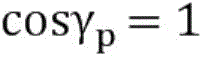
i.e. =0°, that is, when the angle sensor is tilted but not rotated, the rotation angle γ and the horizontal rotation angle
 All 0.
The following table is a record table of the horizontal rotation angle calculated by the formula when the angle sensor is under different measurement conditions.
List I, horizontal rotation angle record list
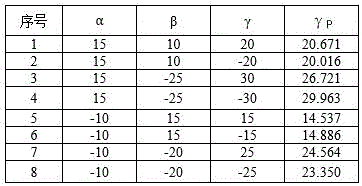
It can be seen that the rotation angle gamma is related to the measured horizontal rotation angle There is a certain gap between the two, which also means that the rotation angle gamma is used for monitoring the horizontal displacement of the soil body, so that a certain error exists in the monitoring result, and the horizontal displacement of the soil body cannot be accurately monitored.
In some embodiments of the present application, prior to placing the angle sensor within the inclinometer pipe, the method further comprises the steps of:
and enabling an X axis in a coordinate system of the angle sensor to be perpendicular to the side surface of the foundation pit, and carrying out rotation angle zeroing on the angle sensor.
By zeroing the angle sensor, the data acquisition accuracy of the angle sensor can be ensured, thereby ensuring the accuracy of the finally obtained horizontal rotation angle.
In some embodiments of the present application, there may be a plurality of detection positions in the inclinometer pipe, and a preset distance is spaced between two adjacent detection positions.
That is, in the measurement process, measurement can be performed for different detection positions in the inclinometer pipe respectively, so as to finally obtain the integral distortion degree of the inclinometer pipe. So that the horizontal displacement of the different section positions of the inclinometer pipe can be more accurately known, and the safety risk degree of the different positions of the foundation pit can be monitored.
In some embodiments of the present application, the angle sensor may include two single-axis tilt sensors and one rotation angle sensor, the two single-axis tilt sensors being vertically arranged, one single-axis tilt sensor being arranged toward the X-axis to acquire the first tilt angle, the other single-axis tilt sensor being arranged toward the Y-axis to acquire the second tilt angle, the rotation angle sensor acquiring the rotation angle.
In some embodiments of the present application, the angle sensor may also include a dual-axis tilt sensor and a rotation angle sensor, the dual-axis tilt sensor acquiring the first tilt angle and the second tilt angle along different directions, respectively, and the rotation angle sensor acquiring the rotation angle.
In some embodiments of the present application, the angle sensor may also be a triaxial angle sensor, where the triaxial angle sensor acquires the first inclination angle, the second inclination angle and the rotation angle along different directions, respectively.
As shown in fig. 10, some embodiments of the present application further provide a measurement apparatus for implementing the measurement method described above. The measurement device includes a housing 320, an angle sensor 370, a cable 210, and a controller 110. The housing 320 is provided with a receiving chamber; the angle sensor 370 is installed in the accommodating chamber; one end of the cable 210 is positioned in the accommodating cavity and is electrically connected with the angle sensor 370, and the other end extends out of the shell 320; the controller 110 is electrically connected to the other end of the cable 210.
The housing 320 is used to provide a mounting space for the angle sensor 370 to protect the angle sensor 370, so that the angle sensor 370 can be placed in a relatively independent space. Meanwhile, as the housing 320 moves up and down within the inclinometer pipe, the angle sensor 370 also moves along with it, thereby allowing for angle measurements at different locations of the inclinometer pipe. The housing 320 may be 316 stainless steel and may be machined.
The cable 210 establishes communication connection between the angle sensor 370 installed in the housing 320 and the controller 110 outside the inclinometer pipe, so that the angle data detected by the angle sensor 370 can be sent to the controller 110 for calculation processing, and finally, the horizontal rotation angle result at the corresponding detection position of the inclinometer pipe is obtained. The controller 110 receives the angle data collected by the angle sensor 370, and the controller 110 can control the angle sensor 370 chip to complete zero-resetting and real-time measurement. The cable 210 may employ a communication cable 210 based on the RS232 form or the RS484 form, and the cable 210 includes two power supply lines to supply the angle sensor 370 with electric power.
In this way, when measuring the horizontal rotation angle at different positions of the inclinometer pipe, it is only necessary to insert the housing 320 into the inclinometer pipe, so that the angle sensor 370 moves up and down in the inclinometer pipe together with the housing 320. And the angle data collected by the angle sensor 370 at a specific position of the inclinometer pipe can be sent to the controller 110 through the cable 210 for calculation processing.
In some embodiments of the present application, a predetermined distance away from the cable 210 Zhou Meige may be provided with an identification location 220.
The specific position of the measuring device within the inclinometer pipe can be clearly known by the identification position 220 of the outer periphery of the cable 210, so that the angle data detected by the angle sensor 370 is correlated with the specific position of the inclinometer pipe.
When the marking position 220 on the periphery of the cable 210 is at the position of the orifice of the inclinometer pipe, the stability of 10S (seconds) is maintained as much as possible, so as to finish the measurement of different angles. And the accuracy of the acquired angle data is ensured by repeatedly reading the data and finally taking an average value. In addition, cable 210 is kept as perpendicular to the foundation pit level as possible during the measurement. Meanwhile, when reading data, the marking position 220 on the cable 210 is kept at the same position of the inclinometer pipe orifice each time.
In practical situations, the preset distance may be set to 500 mm, or may be set to other lengths according to practical situations.
In some embodiments of the present application, the accommodating cavity may have an opening, the housing 320 is provided with a sealing cover plate 310 closing the opening, the sealing cover plate 310 is connected with a waterproof connector 330, a sealing ring 340 is disposed between the waterproof connector 330 and the surface of the sealing cover plate 310, and the other end of the cable 210 sequentially passes through the sealing cover plate 310 and the waterproof connector 330.
In this way, the package cover 310 can be opened, and the installation or replacement of the angle sensor 370 can be rapidly completed. The package cover 310 and the case 320 may be coupled by a fastener such as a screw. The material of the packaging cover plate 310 can be 316 stainless steel, has corrosion resistance, and can be formed by machining. In addition, the sealing between the packaging cover plate 310 and the shell 320 can be realized through the rubber ring 360, and the sealing ring 340 at the waterproof joint 330 is matched with the sealing ring, so that the measuring equipment can be provided with an IP68 waterproof grade.
By providing the waterproof connector 330, the sealing performance of the environment in the accommodating cavity can be ensured, so that the angle sensor 370 is not disturbed by the environment outside the housing 320. The waterproof connector 330 may be made of 316 stainless steel, and meanwhile, the waterproof connector 330 may be a standard component.
In some embodiments of the present application, a guide may be provided outside of housing 320, including a base 410 coupled to housing 320, a guide wheel bracket 430 coupled to base 410, and a guide wheel 440 rotatably disposed on guide wheel bracket 430.
The guiding means may act as a guide for the movement of the measuring device within the inclinometer pipe. The guide pulley 440 may be engaged with a guide groove in the inclinometer pipe so that the detection direction of the angle sensor 370 is consistent with the direction at the corresponding position of the inclinometer pipe. At the same time, the guide wheel 440 may roll along a guide slot in the inclinometer pipe. In addition, the base 410 may be made of 316 stainless steel, and the base 410 may be formed by machining. The connection between the base 410 and the housing 320 may be achieved by fasteners such as bolts. Both idler yoke 430 and idler 440 may be formed of stainless steel and both may be machined.
In some embodiments of the present application, there may be a plurality of guide wheel supports 430 and guide wheels 440, the plurality of guide wheel supports 430 encircle the base 410, the plurality of guide wheels 440 are disposed in one-to-one correspondence with the plurality of guide wheel supports 430, and any two guide wheels 440 are located on the same plane or on two planes perpendicular to each other respectively.
In this way, the guide wheel 440 on the outer side of the base 410 can be kept in a corresponding relationship with the four guide grooves in the inclinometer pipe in a rectangular distribution. That is, any two guide wheels 440 outside the base 410 are located on the same plane or on two planes perpendicular to each other. So that the orientation of the angle sensor 370 is related to the direction of the guide slot in the inclinometer pipe as the angle sensor 370 moves up and down in the inclinometer pipe.
In some embodiments of the present application, an elastic member 420 may be disposed between the guide wheel bracket 430 and the base 410, where the guide wheel bracket 430 is hinged to the base 410, and the elastic member 420 drives the guide wheel bracket 430 to move the guide wheel 440 away from the base 410.
Through the arrangement of the elastic piece 420, the guide wheel 440 can be tensioned, so that the guide wheel 440 can be tightly attached to the bottom wall of the guide groove in the inclinometer when the measuring equipment moves up and down in the inclinometer. Thereby ensuring the stability of the measuring equipment when moving up and down in the inclinometer.
The elastic member 420 may be a torsion spring or an elastic sheet made of stainless steel, or other elastic components.
After the measurement recovery measuring equipment is finished, the torsion spring position of the guide wheel 440 can be washed by water, so that the guide wheel 440 can be normally supported on the bottom wall of the guide groove in the inclinometer pipe when the measuring equipment is used next time.
In some embodiments of the present application, the measuring device may further include a weight 510, the weight 510 being disposed on a side of the base 410 remote from the housing 320.
The weight 510 may add a certain weight to the whole of the measuring apparatus so that the measuring apparatus can be smoothly lowered in the inclinometer pipe. In practical situations, the weight 510 may be made of 316 stainless steel, and the weight 510 may be connected to the base 410 by fasteners such as bolts. Meanwhile, the weight 510 may be replaced according to different situations.
In addition, in order to make the measuring apparatus perform a buffering function during the lowering process in the inclinometer pipe, a side of the weight 510 remote from the base 410 may be provided with a buffering member 610.
The buffer member 610 may be made of a rubber material, the rubber buffer member 610 may be padded at the bottom of the weight member 510, and the buffer member 610 may be coupled to the weight member 510 by a fastener such as a bolt.
As shown in fig. 10, the measuring apparatus integrally includes a sensor chip cavity portion, a middle guide portion, and a bottom weight portion. Wherein, middle direction part and bottom counter weight part can be changed at will according to actual use scene.
In the measuring process of the measuring device, the cable 210 can be connected with the controller 110, and then the guide wheel 440 of the measuring device in the X-axis direction is perpendicular to the foundation pit to perform the rotation angle zeroing operation of the angle sensor 370 chip. The guide wheel 440 of the measuring device is then placed into the inclinometer pipe along the cross guide slot in the inclinometer pipe and the housing 320 of the measuring device is partially lowered to the bottom of the inclinometer pipe. And then manually pulling up the shell 320 of the measuring device to enable the identification position 220 on the cable 210 to be located at the pipe orifice position of the inclinometer, and controlling the measuring device to conduct angle measurement through the controller 110 to obtain and record the torsion angle of the inclinometer at the position.
Thus, as each identification position 220 on the cable 210 reaches the mouth of the inclinometer tube, the twist angle measurements are repeated and recorded until the last identification position 220 on the cable 210 reaches the mouth of the inclinometer tube. After the measurement is completed, the housing 320 portion of the measurement device is recovered, the cable 210 is disconnected from the controller 110, and maintenance of the measurement device is performed.
Fig. 11 shows the structure of the housing part 10 of the measuring device in a position in the inclinometer pipe 20 during measurement, the angle sensor located in the housing part 10 being connected by a cable to a controller located outside the inclinometer pipe 20. By means of this measuring device, measurements of different angles can be achieved at different detection positions within the inclinometer pipe 20. Therefore, the horizontal rotation angle information of the inclinometer 20 at different positions is obtained through calculation, so that the horizontal displacement of the inclinometer 20 at different positions is finally obtained, and the monitoring of the horizontal displacement of the foundation pit soil body is realized.
It will be understood by those of ordinary skill in the art that the foregoing embodiments are specific examples of implementing the present application and that various changes in form and details may be made therein without departing from the spirit and scope of the present application.
Claims (14)
1. A method for measuring the horizontal rotation angle of an inclinometer tube, comprising:
placing an angle sensor in an inclinometer pipe, and enabling the angle sensor to move up and down in the inclinometer pipe;
when the angle sensor reaches a detection position in the inclinometer pipe, respectively acquiring a first inclination angle alpha of the inclinometer pipe relative to a foundation pit horizontal plane along an X-axis direction, a second inclination angle beta of the inclinometer pipe relative to the foundation pit horizontal plane along a Y-axis direction and a rotation angle gamma of the inclinometer pipe around a Z-axis direction by the angle sensor;
the collected angle data is sent to a controller, and the controller calculates the horizontal rotation angle of the inclinometer pipe at the detection position according to the following formula :

The X axis, the Y axis and the Z axis are perpendicular to each other, the X axis, the Y axis and the Z axis are all coordinate axes of the self coordinate system of the angle sensor, the foundation pit horizontal plane is a plane perpendicular to the gravity direction, and the horizontal rotation angle is an included angle formed by projection lines of two side lines forming the rotation angle in the foundation pit horizontal plane.
2. The method of measuring the horizontal rotation angle of a inclinometer according to claim 1, further comprising, prior to said positioning the angle sensor within the inclinometer:
and enabling the X axis in the self coordinate system of the angle sensor to be perpendicular to the side surface of the foundation pit, and carrying out rotation angle zeroing on the angle sensor.
3. The method for measuring the horizontal rotation angle of the inclinometer according to claim 1, wherein a plurality of detection positions are provided in the inclinometer, and two adjacent detection positions are spaced apart by a preset distance.
4. A method of measuring the horizontal rotation angle of a inclinometer according to any one of claims 1 to 3, wherein the angle sensor comprises two single axis tilt sensors and one rotation angle sensor, two single axis tilt sensors are vertically arranged, one single axis tilt sensor is arranged toward the X axis to acquire the first tilt angle, and the other single axis tilt sensor is arranged toward the Y axis to acquire the second tilt angle, and the rotation angle sensor acquires the rotation angle.
5. A method of measuring the horizontal rotation angle of a inclinometer according to any one of claims 1 to 3, wherein the angle sensor comprises a dual-axis inclination sensor that acquires the first inclination angle and the second inclination angle in different directions, respectively, and a rotation angle sensor that acquires the rotation angle.
6. A method of measuring the horizontal rotation angle of a inclinometer according to any one of claims 1 to 3, wherein the angle sensor is a three-axis angle sensor that collects the first inclination angle, the second inclination angle, and the rotation angle in different directions, respectively.
7. A measuring device for carrying out the measuring method according to any one of claims 1 to 6, characterized in that the measuring device comprises:
a housing provided with a receiving chamber;
an angle sensor installed in the accommodation chamber;
one end of the cable is positioned in the accommodating cavity and is electrically connected with the angle sensor, and the other end of the cable extends out of the shell;
and the controller is electrically connected with the other end of the cable.
8. The measurement device of claim 7, wherein the cable is provided with an identification location at a predetermined distance from the cable Zhou Meige.
9. The measuring device according to claim 7, wherein the housing cavity has an opening, a package cover plate for closing the opening is provided on the housing, a waterproof joint is connected to the package cover plate, a sealing ring is provided between the waterproof joint and the surface of the package cover plate, and the other end of the cable passes through the package cover plate and the waterproof joint in sequence.
10. A measuring device according to any one of claims 7 to 9, wherein a guide means is provided outside the housing, the guide means comprising a base connected to the housing, a guide wheel bracket connected to the base, and a guide wheel rotatably provided on the guide wheel bracket.
11. The measuring apparatus of claim 10, wherein the plurality of guide wheel brackets and the plurality of guide wheels are arranged in a one-to-one correspondence manner, and any two guide wheels are positioned on the same plane or on two mutually perpendicular planes respectively.
12. The measurement apparatus of claim 10 wherein an elastic member is disposed between the guide wheel bracket and the base, the guide wheel bracket being hinged to the base, the elastic member driving the guide wheel bracket to move the guide wheel in a direction away from the base.
13. The measurement apparatus of claim 10, further comprising a weight disposed on a side of the base remote from the housing.
14. The measurement apparatus of claim 13 wherein a side of the weight remote from the base is provided with a buffer.
Priority Applications (1)
| Application Number | Priority Date | Filing Date | Title |
|---|---|---|---|
| CN202310250423.8A CN115962752B (en) | 2023-03-16 | 2023-03-16 | Measuring method and measuring equipment for horizontal rotation angle of inclinometer tube |
Applications Claiming Priority (1)
| Application Number | Priority Date | Filing Date | Title |
|---|---|---|---|
| CN202310250423.8A CN115962752B (en) | 2023-03-16 | 2023-03-16 | Measuring method and measuring equipment for horizontal rotation angle of inclinometer tube |
Publications (2)
| Publication Number | Publication Date |
|---|---|
| CN115962752A CN115962752A (en) | 2023-04-14 |
| CN115962752B true CN115962752B (en) | 2023-05-16 |
Family
ID=85899646
Family Applications (1)
| Application Number | Title | Priority Date | Filing Date |
|---|---|---|---|
| CN202310250423.8A Active CN115962752B (en) | 2023-03-16 | 2023-03-16 | Measuring method and measuring equipment for horizontal rotation angle of inclinometer tube |
Country Status (1)
| Country | Link |
|---|---|
| CN (1) | CN115962752B (en) |
Families Citing this family (2)
| Publication number | Priority date | Publication date | Assignee | Title |
|---|---|---|---|---|
| CN117419686B (en) * | 2023-11-14 | 2026-02-24 | 广东省重工建筑设计院有限公司 | Turnover type inclinometer, turnover type inclinometer system and inclination measuring method |
| CN118654639B (en) * | 2024-08-13 | 2025-02-07 | 上海米度测控科技有限公司 | Inclinometer and measurement method for torsion angle displacement compensation |
Citations (9)
| Publication number | Priority date | Publication date | Assignee | Title |
|---|---|---|---|---|
| JP2004125511A (en) * | 2002-09-30 | 2004-04-22 | Tokimec Inc | Gyro apparatus and method of using gyro apparatus for excavation |
| JP2005061969A (en) * | 2003-08-11 | 2005-03-10 | Asahi Kasei Electronics Co Ltd | Azimuthal angle measuring instrument and azimuthal angle measuring method |
| CN101413999A (en) * | 2008-11-12 | 2009-04-22 | 张鹿平 | Method for measuring aerial angle under inclined state |
| CN102536207A (en) * | 2011-12-30 | 2012-07-04 | 中北大学 | Gyro inclinometer attitude measurement solving method applicable to measurement of low well deviation angle |
| CN102809367A (en) * | 2012-08-07 | 2012-12-05 | 西安交通大学 | Space rotating angle measuring method based on double-shaft obliquity sensor |
| CN111765858A (en) * | 2020-06-18 | 2020-10-13 | 中铁第四勘察设计院集团有限公司 | Displacement measuring method, displacement measuring device, inclinometer and computer storage medium |
| CN112857193A (en) * | 2021-03-10 | 2021-05-28 | 桂林电子科技大学 | Three-dimensional intelligent soil displacement monitoring device and method based on MEMS |
| CN115046525A (en) * | 2022-08-15 | 2022-09-13 | 上海米度测控科技有限公司 | Movable inclinometer and method for measuring deep horizontal displacement |
| CN115507813A (en) * | 2022-09-30 | 2022-12-23 | 中航通飞华南飞机工业有限公司 | Space rotation angle measuring method |
-
2023
- 2023-03-16 CN CN202310250423.8A patent/CN115962752B/en active Active
Patent Citations (9)
| Publication number | Priority date | Publication date | Assignee | Title |
|---|---|---|---|---|
| JP2004125511A (en) * | 2002-09-30 | 2004-04-22 | Tokimec Inc | Gyro apparatus and method of using gyro apparatus for excavation |
| JP2005061969A (en) * | 2003-08-11 | 2005-03-10 | Asahi Kasei Electronics Co Ltd | Azimuthal angle measuring instrument and azimuthal angle measuring method |
| CN101413999A (en) * | 2008-11-12 | 2009-04-22 | 张鹿平 | Method for measuring aerial angle under inclined state |
| CN102536207A (en) * | 2011-12-30 | 2012-07-04 | 中北大学 | Gyro inclinometer attitude measurement solving method applicable to measurement of low well deviation angle |
| CN102809367A (en) * | 2012-08-07 | 2012-12-05 | 西安交通大学 | Space rotating angle measuring method based on double-shaft obliquity sensor |
| CN111765858A (en) * | 2020-06-18 | 2020-10-13 | 中铁第四勘察设计院集团有限公司 | Displacement measuring method, displacement measuring device, inclinometer and computer storage medium |
| CN112857193A (en) * | 2021-03-10 | 2021-05-28 | 桂林电子科技大学 | Three-dimensional intelligent soil displacement monitoring device and method based on MEMS |
| CN115046525A (en) * | 2022-08-15 | 2022-09-13 | 上海米度测控科技有限公司 | Movable inclinometer and method for measuring deep horizontal displacement |
| CN115507813A (en) * | 2022-09-30 | 2022-12-23 | 中航通飞华南飞机工业有限公司 | Space rotation angle measuring method |
Non-Patent Citations (2)
| Title |
|---|
| 路基侧向位移观测中测斜管偏转和扭转研究;黄向群 等;《长江科学院报》;第49-52页 * |
| 采用倾角传感器实现空间旋转角度测量的解析方法研究;曹建安;张乐平;吴昊;王亮;苗励文;;西安交通大学学报(第10期);第109-114页 * |
Also Published As
| Publication number | Publication date |
|---|---|
| CN115962752A (en) | 2023-04-14 |
Similar Documents
| Publication | Publication Date | Title |
|---|---|---|
| US4163324A (en) | Surveying of boreholes | |
| AU630571B2 (en) | Borehole deviation monitor | |
| CN105806364B (en) | A kind of calibration method of mining slewing drilling machine inclinometer probe | |
| CN103162677B (en) | Digital geological compass and method for measuring geological occurrence | |
| CA2041207C (en) | Cavity monitoring system | |
| CN110108300A (en) | A kind of IMU regular hexahedron scaling method based on horizontal triaxial turntable | |
| CN115962752A (en) | Method and equipment for measuring horizontal rotation angle of inclinometer pipe | |
| CN115046525B (en) | Movable inclinometer and method for measuring deep horizontal displacement | |
| CN106168462A (en) | Axle precision determination device | |
| CN103424124A (en) | Nonmagnetic inertial navigation unit calibration method based on image measuring technologies | |
| CN114034885B (en) | A testing method of gyro accelerometer on a dual-axis centrifuge based on full error analysis | |
| JPH0457963B2 (en) | ||
| CN108444472A (en) | A kind of underground coal mine hand-held gyrocompass and its measurement method | |
| TW201711796A (en) | Angular error correction device and method for machine tools | |
| AU2023344693A1 (en) | Device for collecting movement trajectory of ore rock in mine blasting | |
| CA2484104C (en) | Method and apparatus for mapping the trajectory in the subsurface of a borehole | |
| CN114395953A (en) | Portable high-pressure water jet steel rail polishing incidence angle calibration method and system | |
| CN118274884B (en) | Error compensation method of inertial measurement unit | |
| CN108036756A (en) | A kind of method that the adjacent axis verticality inspection of dual-axis rotation inertial measuring unit is carried out using accelerometer | |
| RU2152059C1 (en) | Device for positioning of underground pipeline trajectory | |
| KR102249992B1 (en) | Device for Monitoring Open and Close Hydraulic Valve | |
| CN104192166B (en) | Rail attitude measurement method based on earth magnetism sensing and device | |
| CN215374002U (en) | Electronic compass calibrating device | |
| RU2351899C1 (en) | Test bed for carrying out kinematic trials and method of its use | |
| CN117552767A (en) | Directional instrument, and measuring method and system based on directional instrument |
Legal Events
| Date | Code | Title | Description |
|---|---|---|---|
| PB01 | Publication | ||
| PB01 | Publication | ||
| SE01 | Entry into force of request for substantive examination | ||
| SE01 | Entry into force of request for substantive examination | ||
| GR01 | Patent grant | ||
| GR01 | Patent grant |