CN115954773A - A high voltage distribution box - Google Patents
A high voltage distribution box Download PDFInfo
- Publication number
- CN115954773A CN115954773A CN202211601815.6A CN202211601815A CN115954773A CN 115954773 A CN115954773 A CN 115954773A CN 202211601815 A CN202211601815 A CN 202211601815A CN 115954773 A CN115954773 A CN 115954773A
- Authority
- CN
- China
- Prior art keywords
- distribution box
- plate
- voltage distribution
- box body
- baffle
- Prior art date
- Legal status (The legal status is an assumption and is not a legal conclusion. Google has not performed a legal analysis and makes no representation as to the accuracy of the status listed.)
- Granted
Links
Images



Classifications
-
- Y—GENERAL TAGGING OF NEW TECHNOLOGICAL DEVELOPMENTS; GENERAL TAGGING OF CROSS-SECTIONAL TECHNOLOGIES SPANNING OVER SEVERAL SECTIONS OF THE IPC; TECHNICAL SUBJECTS COVERED BY FORMER USPC CROSS-REFERENCE ART COLLECTIONS [XRACs] AND DIGESTS
- Y02—TECHNOLOGIES OR APPLICATIONS FOR MITIGATION OR ADAPTATION AGAINST CLIMATE CHANGE
- Y02A—TECHNOLOGIES FOR ADAPTATION TO CLIMATE CHANGE
- Y02A30/00—Adapting or protecting infrastructure or their operation
- Y02A30/14—Extreme weather resilient electric power supply systems, e.g. strengthening power lines or underground power cables
Landscapes
- Patch Boards (AREA)
Abstract
Description
技术领域technical field
本发明涉及配电箱技术领域,具体为一种高压配电箱。The invention relates to the technical field of distribution boxes, in particular to a high-voltage distribution box.
背景技术Background technique
高压配电箱主要用于电力系统发电、输电、配电、电能转换和消耗的过程中,起到了通断、控制或保护等作用,内部主要包括高压断路器、高压隔离开关与接地开关、高压负荷开关、高压自动重合与分段器,高压配电箱在整个电力工业中占有非常重要的地位,由于高压配电箱内部设置有大量的电力设备,因此尤其需要注意用电安全。The high-voltage distribution box is mainly used in the process of power system power generation, transmission, distribution, power conversion and consumption, and plays the role of on-off, control or protection. It mainly includes high-voltage circuit breakers, high-voltage isolation switches and grounding switches, high-voltage Load switches, high-voltage automatic reclosers and sectionalizers, and high-voltage distribution boxes occupy a very important position in the entire electric power industry. Since there are a large number of electrical equipment inside the high-voltage distribution box, special attention must be paid to the safety of electricity use.
现有技术中,一般通过对工作人员进行培训,形成自我防护,并借助外部的保护工具进行防触电保护,例如绝缘鞋、绝缘手套等工具,但是人工具有大量的不确定性,经常会出现违规操作,在未佩戴充足的防护设备情况中进行操作,该情况下一旦发生漏电的情况,就会造成严重的人员伤害,常规的高压配电箱缺少应对该违规操作情况下的保护机制,另一方面,经常会有在工作完成后未及时关闭柜门,导致外部灰尘飘入到内部的情况,该问题一定程度上影响了内部元件的运行稳定性。In the existing technology, the staff are generally trained to form self-protection, and use external protective tools to protect against electric shock, such as insulated shoes, insulated gloves and other tools, but manual work has a lot of uncertainty, and violations often occur Operate without wearing sufficient protective equipment. In this case, once a leakage occurs, it will cause serious personal injury. The conventional high-voltage distribution box lacks a protection mechanism to deal with this illegal operation. Another On the one hand, there are often situations where the cabinet door is not closed in time after the work is completed, causing external dust to float into the interior. This problem affects the operation stability of internal components to a certain extent.
发明内容Contents of the invention
针对现有技术存在的不足,本发明目的是提供一种高压配电箱,以解决上述背景技术中提出的问题,本发明能够提供触电保护效果,进一步提高了操控时的安全性,能够实现忘记关闭门板时自动闭合的功能,且不需要额外的动力设备。Aiming at the deficiencies in the existing technology, the purpose of the present invention is to provide a high-voltage distribution box to solve the problems raised in the above-mentioned background technology. The present invention can provide electric shock protection effect, further improve the safety during manipulation, and realize The function of automatic closing when the door panel is closed does not require additional power equipment.
为了实现上述目的,本发明是通过如下的技术方案来实现:一种高压配电箱,包括配电箱本体,所述配电箱本体包括箱体、散热除湿组件、保护机构和切换组件,所述箱体的底端安装有底板,所述底板的侧边设置有侧挡板,所述底板的前端安装有保护机构,所述保护机构的前端与配电箱本体所放置的地面上相贴合,所述箱体的前端安装有门板,所述门板的表面安装有密码锁,所述门板的底部一端设置有定位机构,所述侧挡板的前端位置上安装有切换组件,所述切换组件的表面设置有前挡板,所述前挡板的两端均与每个侧挡板部分相接触,所述箱体的顶部安装有进气扇,所述箱体的侧边安装有散热除湿组件。In order to achieve the above object, the present invention is achieved through the following technical solutions: a high-voltage distribution box, including a distribution box body, the distribution box body includes a box body, a heat dissipation and dehumidification component, a protection mechanism and a switching component. The bottom of the box body is equipped with a bottom plate, the side of the bottom plate is provided with side baffles, the front end of the bottom plate is equipped with a protection mechanism, and the front end of the protection mechanism is in close contact with the ground where the distribution box body is placed. The front end of the box body is equipped with a door panel, the surface of the door panel is equipped with a combination lock, the bottom end of the door panel is provided with a positioning mechanism, the front end of the side baffle is equipped with a switch assembly, the switch The surface of the assembly is provided with a front baffle, both ends of the front baffle are in contact with each side baffle part, an air intake fan is installed on the top of the box, and a cooling fan is installed on the side of the box. Dehumidification components.
进一步的,所述保护机构包括绝缘板和凸条,所述绝缘板的后端与底板的前端固定为整体,所述凸条设置在绝缘板后端的上方,所述切换组件设置在保护机构的后端。Further, the protective mechanism includes an insulating plate and a protruding strip, the rear end of the insulating plate is fixed as a whole with the front end of the bottom plate, the protruding strip is arranged above the rear end of the insulating plate, and the switching assembly is arranged on the protective mechanism rear end.
进一步的,所述绝缘板和凸条整体均采用硬质绝缘材料,两个所述侧挡板之间设置有空腔结构,所述切换组件覆盖在该空腔的前端位置上。Further, the insulating plate and the protruding strip are all made of hard insulating material, a cavity structure is provided between the two side baffles, and the switching assembly covers the front end of the cavity.
进一步的,所述切换组件包括前挡板和前凸板,所述前凸板设置在侧挡板的前端位置上,所述前凸板的内部开设有升降槽,所述侧挡板的内侧底部安装有定位基座,所述定位基座的内部开设有收纳孔。Further, the switching assembly includes a front baffle and a front convex plate, the front convex plate is arranged at the front end of the side baffle, a lifting slot is opened inside the front convex plate, and the inner side of the side baffle A positioning base is installed on the bottom, and a storage hole is opened inside the positioning base.
进一步的,所述前挡板的侧边安装有转轴,所述前挡板的底端外侧安装有把手,所述前挡板底端的内侧安装有卡杆,每个所述转轴均插入到相应的升降槽的内部,所述卡杆通过前挡板垂直于底板状态后插入到收纳孔的内部。Further, a rotating shaft is installed on the side of the front baffle, a handle is installed on the outside of the bottom end of the front baffle, and a lever is installed on the inside of the bottom end of the front baffle, and each of the rotating shafts is inserted into a corresponding Inside the lifting slot, the clamping rod is inserted into the inside of the storage hole after the front baffle is perpendicular to the bottom plate.
进一步的,所述绝缘板的表面开设有定位孔,所述卡杆通过前挡板平行于底板的状态后插入到定位孔的内部,且卡杆插入到定位孔内的状态下,此时转轴按压在升降槽的底部位置且前挡板处于水平状态。Further, a positioning hole is opened on the surface of the insulating plate, and the clamping rod is inserted into the positioning hole after the front baffle is parallel to the bottom plate, and when the clamping rod is inserted into the positioning hole, the rotating shaft Press down on the bottom of the lift slot and the front bezel is level.
进一步的,所述散热除湿组件包括出风管和海绵块,所述出风管的一端的侧边设置有进风口,所述出风管的另一端设置有出风口,所述进风口插入到箱体的内部,所述出风口的开口朝向门板的位置。Further, the heat dissipation and dehumidification assembly includes an air outlet pipe and a sponge block, one end of the air outlet pipe is provided with an air inlet, and the other end of the air outlet pipe is provided with an air outlet, and the air inlet is inserted into the Inside the box body, the opening of the air outlet faces the position of the door panel.
进一步的,所述出风口的内部安装有排气扇,所述出风管的一端开口处填装有海绵块,两个所述海绵块贴合的外侧设置有锥面。Further, an exhaust fan is installed inside the air outlet, a sponge block is filled at the opening of one end of the air outlet pipe, and a tapered surface is provided on the outside of the two sponge blocks.
进一步的,所述定位机构包括磁石板和电磁铁,所述箱体的前端设置有托板,所述磁石板嵌装在托板的表面,所述电磁铁安装在门板底部的后端位置上。Further, the positioning mechanism includes a magnet plate and an electromagnet, the front end of the box is provided with a supporting plate, the magnet plate is embedded on the surface of the supporting plate, and the electromagnet is installed at the rear end of the bottom of the door panel .
进一步的,所述门板通过合页与箱体的边缘处活动连接,且磁石板和电磁铁与该合页之间的距离相同,所述电磁铁通过电线与密码锁部分相连接。Further, the door panel is movably connected to the edge of the box body through a hinge, and the magnet plate and the electromagnet are at the same distance from the hinge, and the electromagnet is connected to the combination lock part through wires.
本发明的有益效果:本发明的一种高压配电箱,包括配电箱本体,所述配电箱本体包括箱体、门板、密码锁、进气扇、散热除湿组件、定位机构、侧挡板、切换组件、保护机构、底板、前凸板、升降槽、定位基座、收纳孔、前挡板、转轴、把手、卡杆、绝缘板、凸条、定位孔、出风管、进风口、出风口、海绵块、锥面、排气扇、托板、磁石板、电磁铁。Beneficial effects of the present invention: a high-voltage distribution box of the present invention includes a distribution box body, and the distribution box body includes a box body, a door panel, a combination lock, an air intake fan, a heat dissipation and dehumidification component, a positioning mechanism, and a side guard Plate, switching component, protection mechanism, bottom plate, front convex plate, lifting slot, positioning base, storage hole, front baffle, rotating shaft, handle, clamping rod, insulating plate, raised strip, positioning hole, air outlet pipe, air inlet , Air outlet, sponge block, cone surface, exhaust fan, pallet, magnet plate, electromagnet.
1.该高压配电箱通过底部增加的保护机构,利用绝缘板覆盖整个配电箱前端的地面空间,即可在工作人员进行操控时提供底部额外的绝缘效果,即使发生触电情况,能够在一定程度上减轻电流对接触人体产生的伤害。1. Through the protection mechanism added at the bottom, the high-voltage distribution box uses the insulating plate to cover the ground space at the front of the entire distribution box, which can provide additional insulation at the bottom when the staff is manipulating it. Even if an electric shock occurs, it can Minimize the damage caused by the current to the human body.
2.该高压配电箱通过散热除湿组件能够利用海绵吸附效果除去手掌上的汗渍等水份,避免潮湿的水份进入到配电箱的内部从而提高了触电的风险,充分利用了能源,并配合定位机构能够实现对门板的自动关闭效果。2. The high-voltage power distribution box can use the sponge adsorption effect to remove moisture such as sweat stains on the palm through the heat dissipation and dehumidification components, and prevent moist water from entering the interior of the power distribution box, thereby increasing the risk of electric shock, making full use of energy, and Cooperating with the positioning mechanism can realize the automatic closing effect of the door panel.
3.该高压配电箱通过底部切换组件能够将整个前挡板向外进行翻折,覆盖在保护机构的顶部,作为踩踏区域进行使用,从而在对较高位置的电力设备进行控制时能够更加便于操作,使用更加高效方便。3. The high-voltage power distribution box can fold the entire front baffle outward through the bottom switch assembly, cover the top of the protection mechanism, and use it as a stepping area, so that it can be more efficient when controlling power equipment at a higher position. Easy to operate, more efficient and convenient to use.
附图说明Description of drawings
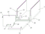
图1为本发明一种高压配电箱的外形的结构示意图;Fig. 1 is the structural representation of the profile of a kind of high voltage distribution box of the present invention;
图2为本发明一种高压配电箱底部的结构示意图;Fig. 2 is a schematic structural view of the bottom of a high-voltage distribution box of the present invention;
图3为本发明一种高压配电箱散热除湿组件部分的结构示意图;Fig. 3 is a structural schematic diagram of a heat dissipation and dehumidification component part of a high-voltage distribution box of the present invention;
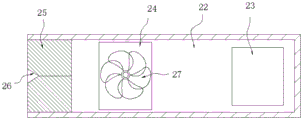
图4为本发明一种高压配电箱散热除湿组件内部的结构示意图;Fig. 4 is a schematic structural diagram of the interior of a heat dissipation and dehumidification component of a high-voltage distribution box according to the present invention;
图5为本发明一种高压配电箱定位机构部分的结构示意图;Fig. 5 is a structural schematic diagram of a positioning mechanism part of a high-voltage distribution box of the present invention;
图中:1、箱体;2、门板;3、密码锁;4、进气扇;5、散热除湿组件;6、定位机构;7、侧挡板;8、切换组件;9、保护机构;10、底板;11、前凸板;12、升降槽;13、定位基座;14、收纳孔;15、前挡板;16、转轴;17、把手;18、卡杆;19、绝缘板;20、凸条;21、定位孔;22、出风管;23、进风口;24、出风口;25、海绵块;26、锥面;27、排气扇;28、托板;29、磁石板;30、电磁铁。In the figure: 1. Box body; 2. Door panel; 3. Combination lock; 4. Intake fan; 5. Heat dissipation and dehumidification component; 6. Positioning mechanism; 7. Side baffle; 8. Switching component; 10. Base plate; 11. Front convex plate; 12. Lifting groove; 13. Positioning base; 14. Storage hole; 15. Front baffle; 16. Rotating shaft; 17. Handle; 20. Raised strip; 21. Positioning hole; 22. Air outlet pipe; 23. Air inlet; 24. Air outlet; 25. Sponge block; 26. Cone surface; 27. Exhaust fan; 28. Support plate; 29. Magnet plate; 30, electromagnet.
具体实施方式Detailed ways
为使本发明实现的技术手段、创作特征、达成目的与功效易于明白了解,下面结合具体实施方式,进一步阐述本发明。In order to make the technical means, creative features, goals and effects achieved by the present invention easy to understand, the present invention will be further described below in conjunction with specific embodiments.
请参阅图1至图5,本发明提供一种技术方案:一种高压配电箱,包括配电箱本体,所述配电箱本体包括箱体1、散热除湿组件5、保护机构9和切换组件8,所述箱体1的底端安装有底板10,所述底板10的侧边设置有侧挡板7,所述底板10的前端安装有保护机构9,所述保护机构9的前端与配电箱本体所放置的地面上相贴合,所述箱体1的前端安装有门板2,所述门板2的表面安装有密码锁3,所述门板2的底部一端设置有定位机构6,所述侧挡板7的前端位置上安装有切换组件8,所述切换组件8的表面设置有前挡板15,所述前挡板15的两端均与每个侧挡板7部分相接触,所述箱体1的顶部安装有进气扇4,所述箱体1的侧边安装有散热除湿组件5,该高压配电箱整体呈立式结构,将多种电气设备放置在箱体1的内部,通过前端的门板2进行封堵遮挡,利用侧边的散热除湿组件5实现对箱体1内部的散热处理,并在底部设置有相应的保护机构9,使用时,通过控制门板2上的密码锁3,即可将门板2进行开启,开启时通过定位组件即可将门板2进行吸附和定位,并通过将定位组件接入到现有的控制系统中,利用常规的控制程序将开启密码锁3后向电磁铁30中通入一定时间的电流,即可实现将门板2在一定时间内施加吸附效果。Please refer to Figures 1 to 5, the present invention provides a technical solution: a high-voltage distribution box, including a distribution box body, the distribution box body includes a box body 1, a heat dissipation and
本实施例,所述保护机构9包括绝缘板19和凸条20,所述绝缘板19的后端与底板10的前端固定为整体,所述凸条20设置在绝缘板19后端的上方,所述切换组件8设置在保护机构9的后端,所述绝缘板19和凸条20整体均采用硬质绝缘材料,两个所述侧挡板7之间设置有空腔结构,所述切换组件8覆盖在该空腔的前端位置上,通过底部增加的保护机构9,利用绝缘板19覆盖整个配电箱前端的地面空间,即可在工作人员进行操控时提供底部额外的绝缘效果,即使发生触电情况,能够在一定程度上减轻电流对接触人体产生的伤害,且及时工作人员未穿戴绝缘鞋的情况下仍旧有效,具体的,工作人员需要对该配电箱进行操控调节时,直接站立在绝缘板19上,绝缘板19将上方站立的人员与地面隔绝,即可在后期一旦发生触电情况时,阻断电流沿着人体导入到大地,该情况下人体呈断路状态,因此能够避免全部电流从人体流过,实现了一定程度上的防触电功能。In this embodiment, the protection mechanism 9 includes an insulating
本实施例,所述切换组件8包括前挡板15和前凸板11,所述前凸板11设置在侧挡板7的前端位置上,所述前凸板11的内部开设有升降槽12,所述侧挡板7的内侧底部安装有定位基座13,所述定位基座13的内部开设有收纳孔14,所述前挡板15的侧边安装有转轴16,所述前挡板15的底端外侧安装有把手17,所述前挡板15底端的内侧安装有卡杆18,每个所述转轴16均插入到相应的升降槽12的内部,所述卡杆18通过前挡板15垂直于底板10状态后插入到收纳孔14的内部,所述绝缘板19的表面开设有定位孔21,所述卡杆18通过前挡板15平行于底板10的状态后插入到定位孔21的内部,且卡杆18插入到定位孔21内的状态下,此时转轴16按压在升降槽12的底部位置且前挡板15处于水平状态,通过底部切换组件8能够将整个前挡板15向外进行翻折,覆盖在保护机构9的顶部,作为踩踏区域进行使用,从而在对较高位置的电力设备进行控制时能够更加便于操作,使用更加高效方便,且不会影响绝缘保护的效果,常态下如附图1所示.前挡板15垂直收纳在侧挡板7前方,当工作人员需要对配电箱的顶部进行操作时,直接将把手17前拉,将卡杆18插入到定位孔21内,即可将前挡板15水平放置,作为踩踏的台阶使用。In this embodiment, the switching
本实施例,所述散热除湿组件5包括出风管22和海绵块25,所述出风管22的一端的侧边设置有进风口23,所述出风管22的另一端设置有出风口24,所述进风口23插入到箱体1的内部,所述出风口24的开口朝向门板2的位置,所述出风口24的内部安装有排气扇27,所述出风管22的一端开口处填装有海绵块25,两个所述海绵块25贴合的外侧设置有锥面26,通过散热除湿组件5能够在工作人员进行操控前将手插入到海绵块25的内部,利用海绵吸附效果除去手掌上的汗渍等水份,避免潮湿的水份进入到配电箱的内部从而提高了触电的风险,且该结构依靠于散热系统产生的气流,不需要额外的干燥组件,充分利用了能源,降低了成本,并配合定位机构6能够实现对门板2的自动关闭效果,利用出风管22内部的气流,即可持续对海绵块25进行烘干,进一步提高了去除手上水份的效果。In this embodiment, the heat dissipation and
本实施例,所述定位机构6包括磁石板29和电磁铁30,所述箱体1的前端设置有托板28,所述磁石板29嵌装在托板28的表面,所述电磁铁30安装在门板2底部的后端位置上,所述门板2通过合页与箱体1的边缘处活动连接,且磁石板29和电磁铁30与该合页之间的距离相同,所述电磁铁30通过电线与密码锁3部分相连接,具体的,开启密码锁3时,即可通过相应的程序向电磁铁30内部通入电流使其具有磁性,此时打开门板2即可利用磁石板29与电磁铁30吸附,该状态下门板2不会闭合,当工作人员离开后若发生忘记关闭门板2的情况,通入到电磁铁30中的电流会在设定的时间后断开,磁石板29与电磁铁30不再吸附,因此通过出风口24吹出的气流即可缓慢将门板2进行闭合,避免长时间的开启。In this embodiment, the
以上显示和描述了本发明的基本原理和主要特征和本发明的优点,对于本领域技术人员而言,显然本发明不限于上述示范性实施例的细节,而且在不背离本发明的精神或基本特征的情况下,能够以其他的具体形式实现本发明。因此,无论从哪一点来看,均应将实施例看作是示范性的,而且是非限制性的,本发明的范围由所附权利要求而不是上述说明限定,因此旨在将落在权利要求的等同要件的含义和范围内的所有变化囊括在本发明内。不应将权利要求中的任何附图标记视为限制所涉及的权利要求。The basic principles and main features of the present invention and the advantages of the present invention have been shown and described above. For those skilled in the art, it is obvious that the present invention is not limited to the details of the above-mentioned exemplary embodiments, and without departing from the spirit or fundamentals of the present invention. The present invention can be implemented in other specific forms without any specific features. Accordingly, the embodiments should be regarded in all points of view as exemplary and not restrictive, the scope of the invention being defined by the appended claims rather than the foregoing description, and it is therefore intended that the scope of the invention be defined by the appended claims rather than by the foregoing description. All changes within the meaning and range of equivalents of the elements are embraced in the present invention. Any reference sign in a claim should not be construed as limiting the claim concerned.
此外,应当理解,虽然本说明书按照实施方式加以描述,但并非每个实施方式仅包含一个独立的技术方案,说明书的这种叙述方式仅仅是为清楚起见,本领域技术人员应当将说明书作为一个整体,各实施例中的技术方案也可以经适当组合,形成本领域技术人员可以理解的其他实施方式。In addition, it should be understood that although this specification is described according to implementation modes, not each implementation mode only contains an independent technical solution, and this description in the specification is only for clarity, and those skilled in the art should take the specification as a whole , the technical solutions in the various embodiments can also be properly combined to form other implementations that can be understood by those skilled in the art.
Claims (10)
Priority Applications (1)
| Application Number | Priority Date | Filing Date | Title |
|---|---|---|---|
| CN202211601815.6A CN115954773B (en) | 2022-12-13 | 2022-12-13 | High-voltage distribution box |
Applications Claiming Priority (1)
| Application Number | Priority Date | Filing Date | Title |
|---|---|---|---|
| CN202211601815.6A CN115954773B (en) | 2022-12-13 | 2022-12-13 | High-voltage distribution box |
Publications (2)
| Publication Number | Publication Date |
|---|---|
| CN115954773A true CN115954773A (en) | 2023-04-11 |
| CN115954773B CN115954773B (en) | 2023-08-25 |
Family
ID=87290002
Family Applications (1)
| Application Number | Title | Priority Date | Filing Date |
|---|---|---|---|
| CN202211601815.6A Active CN115954773B (en) | 2022-12-13 | 2022-12-13 | High-voltage distribution box |
Country Status (1)
| Country | Link |
|---|---|
| CN (1) | CN115954773B (en) |
Cited By (1)
| Publication number | Priority date | Publication date | Assignee | Title |
|---|---|---|---|---|
| CN116914579A (en) * | 2023-09-07 | 2023-10-20 | 河南澳美电气有限公司 | An electrical integrated distribution cabinet |
Citations (7)
| Publication number | Priority date | Publication date | Assignee | Title |
|---|---|---|---|---|
| CN104505725A (en) * | 2014-11-18 | 2015-04-08 | 江苏辰宇电气有限公司 | Convenient-to-maintain power distribution cabinet |
| CN206947776U (en) * | 2017-05-18 | 2018-01-30 | 广东兆华电业有限公司 | Electrocution-proof switch cabinet |
| CN209029731U (en) * | 2018-12-29 | 2019-06-25 | 山西农业大学信息学院 | A kind of moisture-proof electrical cabinet |
| CN210669160U (en) * | 2019-10-24 | 2020-06-02 | 湖南天宇自控工程有限公司 | Outdoor block terminal of protection against electric shock |
| CN212849347U (en) * | 2020-10-09 | 2021-03-30 | 李大卫 | Dampproofing net electric automatization switch board of joining in marriage |
| CN212849441U (en) * | 2020-07-31 | 2021-03-30 | 国网山西省电力公司 | New energy grid-connected consumption capability analysis device based on Internet |
| CN113700387A (en) * | 2021-08-11 | 2021-11-26 | 刘茂发 | Stainless steel explosion-proof power distribution cabinet |
-
2022
- 2022-12-13 CN CN202211601815.6A patent/CN115954773B/en active Active
Patent Citations (7)
| Publication number | Priority date | Publication date | Assignee | Title |
|---|---|---|---|---|
| CN104505725A (en) * | 2014-11-18 | 2015-04-08 | 江苏辰宇电气有限公司 | Convenient-to-maintain power distribution cabinet |
| CN206947776U (en) * | 2017-05-18 | 2018-01-30 | 广东兆华电业有限公司 | Electrocution-proof switch cabinet |
| CN209029731U (en) * | 2018-12-29 | 2019-06-25 | 山西农业大学信息学院 | A kind of moisture-proof electrical cabinet |
| CN210669160U (en) * | 2019-10-24 | 2020-06-02 | 湖南天宇自控工程有限公司 | Outdoor block terminal of protection against electric shock |
| CN212849441U (en) * | 2020-07-31 | 2021-03-30 | 国网山西省电力公司 | New energy grid-connected consumption capability analysis device based on Internet |
| CN212849347U (en) * | 2020-10-09 | 2021-03-30 | 李大卫 | Dampproofing net electric automatization switch board of joining in marriage |
| CN113700387A (en) * | 2021-08-11 | 2021-11-26 | 刘茂发 | Stainless steel explosion-proof power distribution cabinet |
Cited By (2)
| Publication number | Priority date | Publication date | Assignee | Title |
|---|---|---|---|---|
| CN116914579A (en) * | 2023-09-07 | 2023-10-20 | 河南澳美电气有限公司 | An electrical integrated distribution cabinet |
| CN116914579B (en) * | 2023-09-07 | 2024-01-16 | 河南澳美电气有限公司 | Integrated switch board of electrical apparatus |
Also Published As
| Publication number | Publication date |
|---|---|
| CN115954773B (en) | 2023-08-25 |
Similar Documents
| Publication | Publication Date | Title |
|---|---|---|
| CN115954773B (en) | High-voltage distribution box | |
| CN209766971U (en) | Switchgear and its cooling mechanism | |
| CN208623132U (en) | A kind of high-voltage switch gear control cabinet with radiating dustproof | |
| CN107912010B (en) | A kind of anti-interference power equipment based on shielded layer principle | |
| CN209344577U (en) | A kind of distribution box with long service life | |
| CN219497496U (en) | Transformer protection shell | |
| CN206250642U (en) | Switchyard casing | |
| CN211508213U (en) | Electrical safety switch cabinet | |
| CN221947648U (en) | Safe type regulator cubicle | |
| CN212907590U (en) | A withdrawable switch circuit breaker | |
| CN208707168U (en) | A kind of high-voltage terminal cabinet with decompression function | |
| CN208257227U (en) | A kind of high and low voltage switchgear with heat sinking function | |
| CN209071889U (en) | A kind of power generation distribution box | |
| CN216959055U (en) | Multifunctional soft start cabinet | |
| CN218648434U (en) | A high and low voltage complete switchgear with a refrigeration mechanism | |
| CN221842148U (en) | A complete set of electrical switch cabinet body | |
| CN218887860U (en) | Self-service terminal switch board of handling electric in business office | |
| CN214124375U (en) | Commercial low-voltage apparatus power-saving control cabinet | |
| CN212085587U (en) | Modular intelligent power grid switch cabinet | |
| CN221669310U (en) | Three-phase safety power consumption management platform monitoring device | |
| CN216903973U (en) | Cubical switchboard with dustproof construction | |
| CN217217225U (en) | Be used for open air electrical control cabinet | |
| CN215419202U (en) | High-voltage electrical cabinet with heat abstractor | |
| CN219659251U (en) | A new type of combined switch cabinet | |
| CN220382495U (en) | An electrical automation control box |
Legal Events
| Date | Code | Title | Description |
|---|---|---|---|
| PB01 | Publication | ||
| PB01 | Publication | ||
| SE01 | Entry into force of request for substantive examination | ||
| SE01 | Entry into force of request for substantive examination | ||
| TA01 | Transfer of patent application right |
Effective date of registration: 20230804 Address after: 071000 office building, No. 202, Xingyuan modern city, No. 79, swan Middle Road, Baoding City, Hebei Province Applicant after: HEBEI XINDA CHANGYUAN ELECTRIC POWER TECHNOLOGY CO.,LTD. Address before: Room 01 and Room 02, 10th Floor, Building 2, SAGE Technology R&D Center, No. 26 Binhu Road, Donghu New Technology Development Zone, Wuhan City, Hubei Province, 430000 (multiple photos of one site) Applicant before: Wuhan Shengyu Intelligent Technology Co.,Ltd. |
|
| TA01 | Transfer of patent application right | ||
| GR01 | Patent grant | ||
| GR01 | Patent grant | ||
| PE01 | Entry into force of the registration of the contract for pledge of patent right |
Denomination of invention: Device, system and method for controlling high-voltage distribution box Granted publication date: 20230825 Pledgee: Shunping Rural Credit Union Co.,Ltd. Pledgor: HEBEI XINDA CHANGYUAN ELECTRIC POWER TECHNOLOGY CO.,LTD. Registration number: Y2025980029838 |
|
| PE01 | Entry into force of the registration of the contract for pledge of patent right |