CN115954772A - An intelligent high-pressure floor-standing metering box - Google Patents
An intelligent high-pressure floor-standing metering box Download PDFInfo
- Publication number
- CN115954772A CN115954772A CN202210908542.3A CN202210908542A CN115954772A CN 115954772 A CN115954772 A CN 115954772A CN 202210908542 A CN202210908542 A CN 202210908542A CN 115954772 A CN115954772 A CN 115954772A
- Authority
- CN
- China
- Prior art keywords
- voltage
- phase
- room
- metering
- circuit breaker
- Prior art date
- Legal status (The legal status is an assumption and is not a legal conclusion. Google has not performed a legal analysis and makes no representation as to the accuracy of the status listed.)
- Pending
Links
Images




Landscapes
- Patch Boards (AREA)
Abstract
Description
技术领域technical field
本发明涉及10kV高压供电高压计量领域,具体涉及一种智能型高压落地式计量箱。The invention relates to the field of high-voltage metering for 10kV high-voltage power supply, in particular to an intelligent high-voltage floor-standing metering box.
背景技术Background technique
常规的10kV高压供电高压计量方案,采用柱上断路器和组合式计量单元(集成电流互感器和电压互感器)来实现。柱上断路器和组合式计量单元安装在两根电线杆的横担上,而安装微机保护装置的控制箱和安装电能表的计量箱安装在电线杆上,避雷器也安装在电线杆上,他们之间通过高压电线连接起来。考虑到使用安全,柱上断路器、组合式计量单元、避雷器、高压连接线都安装在距离地面大约6米的电线杆上,控制箱和计量箱安装在距离地面大约3.5米的电线杆上。The conventional 10kV high-voltage power supply high-voltage metering scheme is realized by using a pole-mounted circuit breaker and a combined metering unit (integrated current transformer and voltage transformer). The circuit breaker on the pole and the combined metering unit are installed on the cross arms of the two utility poles, while the control box with the microcomputer protection device and the metering box with the electric energy meter are installed on the utility poles, and the lightning arrester is also installed on the utility poles. connected by high voltage wires. Considering the safety of use, the pole-mounted circuit breaker, combined metering unit, lightning arrester, and high-voltage connecting line are all installed on the pole about 6 meters above the ground, and the control box and metering box are installed on the pole about 3.5 meters above the ground.
在实际使用过程中,柱上断路器的分合闸状态、储能状态,计量单元的使用状态,电线接头是否牢固可靠,元器件是否有裂纹或者老化等,在地面上无法观察到,如果元器件出线问题,无法及时发现,容易造成安全隐患和安全事故。柱上断路器的分合闸操作和储能操作也需要操作工人站在地面上,通过一根大约5米长的绝缘操作杆来操作断路器的分合闸和储能,操作起来非常不方便。在柱上断路器与微机保护装置调试过程中,需要爬到电线杆上,来设置微机保护的保护定值;在抄表时,也需要爬到电线杆上来记录电能计量表的度数,这些操作都会高空跌落和触电风险,对操作人员的安全造成威胁。In the actual use process, the opening and closing status of the circuit breaker on the pole, the energy storage status, the usage status of the metering unit, whether the wire connector is firm and reliable, whether the components are cracked or aging, etc., cannot be observed on the ground. The problem of device outlets cannot be found in time, which may easily cause safety hazards and safety accidents. The opening and closing operation and energy storage operation of the circuit breaker on the pole also requires the operator to stand on the ground and operate the opening, closing and energy storage of the circuit breaker through an insulating operating rod about 5 meters long, which is very inconvenient to operate . During the debugging process of the circuit breaker on the pole and the microcomputer protection device, it is necessary to climb on the electric pole to set the protection setting value of the microcomputer protection; when reading the meter, it is also necessary to climb on the electric pole to record the degree of the electric energy meter. These operations There will be risks of falling from high altitude and electric shock, posing a threat to the safety of operators.
柱上断路器、计量单元、高压电线、避雷器等高压带电部件,裸露在空气中,在潮湿、多尘、污秽的环境中,容易导致绝缘击穿,危害设备和人身安全。而且在这个高度,树枝或其他异物也容易造成两相或者三相短路,影响设备工作的可靠性。裸露在空气中长时间的工作,自然的风吹日晒,容易造成绝缘老化,元器件龟裂,降低产品的使用寿命和工作的可靠性。Pole-mounted circuit breakers, metering units, high-voltage wires, lightning arresters and other high-voltage live parts are exposed to the air, and in humid, dusty, and dirty environments, it is easy to cause insulation breakdown and endanger equipment and personal safety. Moreover, at this height, tree branches or other foreign objects are likely to cause two-phase or three-phase short circuits, which will affect the reliability of the equipment. Exposure to the air for a long time, natural wind and sun, will easily cause insulation aging, cracks in components, and reduce the service life and reliability of the product.
发明内容Contents of the invention
为解决上述问题,提供一种智能型高压落地式计量箱,本发明的技术方案是以下述方式实现的:In order to solve the above problems, an intelligent high-pressure floor-standing metering box is provided. The technical solution of the present invention is realized in the following manner:
一种智能型高压落地式计量箱,包括计量箱本体, 所述的柜体的内部通过金属隔板分割为独立的进线室、出线室、控制室、计量室、操作室,所述的进线室、出线室、控制室、计量室、操作室分别设置有开关门,所述的控制室和计量室的开关门为双层门,控制室门板上安装有微机保护装置、强制型带电显示器、分闸按钮8、合闸按钮、储能旋钮;所述的进线室安装有柱上断路器,柱上断路器通过柱上支架安装在进线室底部,柱上断路器的三个进线端分别连接A相高压进线铜排、B相高压进线铜排和C相高压进线铜排,柱上断路器的三个出线端分别连接三个保护电流互感器,三个保护电流互感器分别连接A相高压出线铜排、B相高压出线铜排和C相高压出线铜排。An intelligent high-voltage floor-standing metering box, including a metering box body, the interior of the cabinet is divided into independent wire inlet rooms, wire outlet rooms, control rooms, metering rooms, and operating rooms through metal partitions. The line room, outlet room, control room, metering room, and operating room are respectively equipped with switch doors. The switch doors of the control room and the metering room are double-layer doors, and the control room door is equipped with a microcomputer protection device and a forced live display. , switch-off
所述的A相高压进线铜排、B相高压进线铜排和C相高压进线铜排分别并联有避雷器。The A-phase high-voltage incoming copper bar, the B-phase high-voltage incoming copper bar and the C-phase high-voltage incoming copper bar are respectively connected in parallel with lightning arresters.
所述的A相高压进线铜排和B相高压进线铜排并联有供电电压互感器,所属的供电电压互感器变比为10kV/0.22kV。The A-phase high-voltage incoming line copper bar and the B-phase high-voltage incoming line copper bar are connected in parallel with power supply voltage transformers, and the transformation ratio of the power supply voltage transformers is 10kV/0.22kV.
所述的A相高压出线铜排连接A相计量电压互感器、C相高压出线铜排连接C相计量电压互感器, A相高压出线铜排连接A相计量电流互感器、C相高压出线铜排连接C相计量电流互感器, B相高压出线铜排连接A相计量电压互感器和C相计量电压互感器。The phase A high-voltage outlet copper bar is connected to the A-phase metering voltage transformer, the C-phase high-voltage outlet copper bar is connected to the C-phase metering voltage transformer, the A-phase high-voltage outlet copper bar is connected to the A-phase metering current transformer, and the C-phase high-voltage outlet copper bar is connected to the C-phase metering voltage transformer. The bus bar is connected to the C-phase metering current transformer, and the B-phase high-voltage outlet copper bar is connected to the A-phase metering voltage transformer and the C-phase metering voltage transformer.
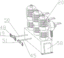
所述的柱上断路器安装有分合闸操作轴50和储能操作轴45,所述的分合闸操作轴50和储能操作轴45延伸到操作室。The pole-mounted circuit breaker is equipped with an opening and
所述的操作室设置有分合闸观察窗47和储能观察窗46。The operating room is provided with an opening and
所述的计量室设置有观察窗,所述的观察窗采用透明有机玻璃制作。The metering chamber is provided with an observation window, and the observation window is made of transparent plexiglass.
所述的柱上断路器的保护CT变比可调,柱上断路器CT变比是200/5、400/5、600/5三档可调。The protective CT transformation ratio of the pole-mounted circuit breaker is adjustable, and the CT transformation ratio of the pole-mounted circuit breaker is adjustable in three levels: 200/5, 400/5, and 600/5.
所述的进线室开关门内侧安装有第一电磁锁,出线室开关门内侧安装有第二电磁锁, 第一电磁锁和第二电磁锁电连接强制型带电显示器。A first electromagnetic lock is installed on the inner side of the switch door of the inlet room, and a second electromagnetic lock is installed on the inner side of the switch door of the outlet room. The first electromagnetic lock and the second electromagnetic lock are electrically connected to the mandatory charged display.
后门内侧边缘设置有插销安装板。A bolt mounting plate is arranged on the inner edge of the rear door.
相对于现有技术,本发明的具有以下有益效果:Compared with the prior art, the present invention has the following beneficial effects:
一种智能型高压落地式计量箱,包括计量箱本体,所述的柜体的内部通过金属隔板分割为独立的进线室、出线室、控制室、计量室、操作室,所述的进线室、出线室、控制室、计量室、操作室分别设置有开关门,所述的控制室和计量室的开关门为双层门,控制室门板上安装有微机保护装置,强制型带电显示器,分闸按钮8,合闸按钮,储能旋钮;所述的进线室安装有柱上断路器,柱上断路器通过柱上支架安装在进线室底部,柱上断路器的三个进线端分别连接A相高压进线铜排、B相高压进线铜排和C相高压进线铜排,柱上断路器的三个出线端分别连接三个保护电流互感器,三个保护电流互感器连接A相高压出线铜排、B相高压出线铜排和C相高压出线铜排,通过该发明的可以有效的保护人身安全,且采用独一元器件的拼接安装,成本比较低,且检修方便,若检测到个别零件损坏,容易检修。An intelligent high-voltage floor-standing metering box, including a metering box body, the interior of the cabinet is divided into independent wire inlet rooms, wire outlet rooms, control rooms, metering rooms, and operating rooms through metal partitions. The line room, outlet room, control room, metering room, and operating room are respectively equipped with switch doors. The switch doors of the control room and the metering room are double-layer doors, and a microcomputer protection device is installed on the door panel of the control room. , switch-off
附图说明Description of drawings
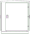
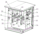
图1是本发明的左视图。Fig. 1 is a left side view of the present invention.
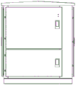
图2是本发明的主视图。Fig. 2 is a front view of the present invention.
图3是本发明的右视图。Fig. 3 is a right side view of the present invention.
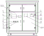
图4是本发明的控制室和计量室。Figure 4 is the control chamber and metering chamber of the present invention.
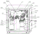
图5是正视图视图(隐藏前门板,隐藏观察窗门板)。Figure 5 is a front view (hiding the front door panel and hiding the observation window door panel).
图6是内部示意图1。FIG. 6 is an internal schematic diagram 1 .
图7是内部示意图2。FIG. 7 is an internal schematic diagram 2 .
图8为柱上断路器示意图。Fig. 8 is a schematic diagram of a pole-mounted circuit breaker.
图9为控制室示意图。Figure 9 is a schematic diagram of the control room.
图10为柱上断路器保护CT变比可调结构1。Fig. 10 is a pole-mounted circuit breaker protection CT transformation ratio adjustable structure 1.
图11为柱上断路器保护CT变比可调结构2。Fig. 11 is the pole-mounted circuit breaker protection CT transformation ratio
图12为电磁锁示意图1。Fig. 12 is a schematic diagram 1 of the electromagnetic lock.
图13为电磁锁示意图2。Fig. 13 is a schematic diagram 2 of the electromagnetic lock.
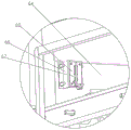
图14为后门插销安装板结构1。Fig. 14 is the rear door latch mounting plate structure 1.
图15为后门插销安装板结构2。Fig. 15 is the rear door latch
具体实施方式Detailed ways
下面结合附图和具体实施方式对本发明作进一步详细说明。The present invention will be described in further detail below in conjunction with the accompanying drawings and specific embodiments.
为使本发明实施方式的目的、技术方案和优点更加清楚,下面将结合本发明实施方式中的附图,对本发明实施方式中的技术方案进行清楚、完整地描述,显然,所描述的实施方式是本发明一部分实施方式,而不是全部的实施方式。基于本发明中的实施方式,本领域普通技术人员在没有作出创造性劳动前提下所获得的所有其他实施方式,都属于本发明保护的范围。In order to make the purpose, technical solutions and advantages of the embodiments of the present invention clearer, the technical solutions in the embodiments of the present invention will be clearly and completely described below in conjunction with the accompanying drawings in the embodiments of the present invention. Obviously, the described embodiments It is some embodiments of the present invention, but not all of them. Based on the implementation manners in the present invention, all other implementation manners obtained by persons of ordinary skill in the art without creative efforts fall within the protection scope of the present invention.
如图1-15所示的一种集成三段保护、五室隔开的智能型高压落地式计量箱,高压落地式计量箱总体包括5个部分:进线室101、出线室102、控制室103、计量室104、操作室42,五室通过金属隔板分开,独立成室,保证相互独立,互不影响。As shown in Figure 1-15, an intelligent high-voltage floor-standing metering box with integrated three-stage protection and five compartments is separated. The high-voltage floor-standing metering box generally includes five parts: the
该计量箱前后左右设置有开关门,开关门铰接在立柱型材上,计量箱前部为双层门设计,前门1左侧铰接在计量箱立柱型材上,前门1右侧中间位置设置有开启前门1的把手1001,前门1内部设置有控制室103和计量室104,控制室103分布在左侧,计量室104分布在右侧,控制室103和计量室104,可以对微机保护进行参数设置和调试,也可以观察到计量室内的计量表读数,进行计量表抄表。The metering box is equipped with open and close doors, which are hinged on the column profile. The front part of the metering box is a double-layer door design. The left side of the front door 1 is hinged on the column profile of the metering box. The
控制室103内部设置有控制室门板5,控制室门板5铰接在左侧立柱上,控制室门板5上分布安装有微机保护装置7,强制型带电显示器6,分闸按钮8,分闸按钮8集成指示灯,合闸按钮9,合闸按钮9集成指示灯,储能旋钮10。在不打开控制室门板5的情况下,可以对微机保护装置进行参数设置和与断路器的联调,并且可以通过分合闸按钮控制断路器的分合闸,通过储能旋钮来对断路器机构进行储能操作。强制型带电显示器6接收来自高压传感器的感应电压信号,来指示高压侧是否带电。The
计量室104内部设置有计量室门板11,计量室门板11铰接在右侧立柱上,计量室门板11上部设置有两个观察窗:电能计量表观察窗13和电能采集终端观察窗14,电能计量表观察窗13和电能采集终端观察窗14采用透明有机玻璃制作。在不打开计量室门板的情况下,通过电能计量表观察窗13,可以看到电能表的用电量,通过电能采集终端观察窗14,可以看到电能采集终端的实时数字显示。The
进线室观察窗和出线室观察窗设计,在控制室和计量室上部设置有进线室观察窗门板和出线室观察窗观察窗门板,进线室观察窗门板和出线室观察窗观察窗门板分别铰接在左右立柱上,进线室观察窗门板上设置有进线室观察窗15,出线室观察窗门板上设置有出线室观察窗,进线室观察窗15可以看到进线室内的供电电压互感器、柱上断路器、高压熔断器、避雷器、高压进线电缆和电缆头等的工作状态。出线室观察窗16可以看到出线室内的计量电流互感器、计量电压互感器、高压熔断器、出线电缆和电缆头等的工作状态。通过两个观察窗,如果进线室和出线室内的元器件有老化龟裂、火花放电、污垢和凝露等情况,都可以及时发现,及时处理,防止事故的发生。The observation window of the incoming line room and the observation window of the outgoing line room are designed. The observation window door panel of the incoming line room and the observation window of the outgoing line room are arranged on the upper part of the control room and the metering room. The observation window door panel of the incoming line room and the observation window of the outgoing line room are installed. Respectively hinged on the left and right columns, the inlet room observation window door panel is provided with an inlet
进线室元器件结构布置,计量箱左侧位置为进线室,计量箱右侧位置为出线室,进线室和出线室之间设置有计量箱中间隔板28,对进线室和出线室分隔开,使进线室和出线室单独成室,在进线室内部,箱体底部开有电缆进线孔25;在进线室底部设置有柱上断路器支架24,柱上断路器支架24上部螺钉固定柱上断路器20,柱上断路器20包括下部的机构箱和机构箱上部的三个极柱,三个极柱为柱上断路器20的进线端,柱上断路器20三个极柱上分别螺栓固定A相高压出线铜排221、B相高压出线铜排222和C相高压出线铜排223,A相高压出线铜排221、B相高压出线铜排222和C相高压出线铜排223均为L型,三个高压进线铜排远离柱上断路器20一端设置有长圆孔,用来固定从电缆进线孔25穿过来的高压电缆线,A相高压出线铜排221、B相高压出线铜排222和C相高压出线铜排223分别上固定有三个高压传感器21,高压进线铜排通过高压传感器21进行固定在计量箱上,高压传感器21感应电源电压,与带电显示器6配合可指示计量箱进线端是否带电。在高压进线铜排22上部,并联有避雷器19,如果有雷电过电压或者操作过电压,避雷器可以对柱上断路器20、电流互感器23、A相计量电压互感器29,C相计量电压互感器30等一次部件进行限压保护,防止一次元器件因为过电压而绝缘击穿造成损坏。如图所示的高压进线铜排22的数量为三个,分别为A向高压进线铜排221,B向高压进线铜排222和C向高压进线铜排223,在A向高压进线铜排221和B向高压进线铜排222上,还并联有供电电压互感器17,变比为10kV/0.22kV,为微机保护、照明灯、柱上断路器电动机构提供220V电源。电压互感器17和A向高压进线铜排221以及电压互感器17和B向高压进线铜排222之间串联两个高压熔断器18,如果电压互感器后端负载有短路等异常情况,熔断器可迅速熔断,对电压互感器17进行保护。Structural arrangement of components in the incoming line room. The left side of the metering box is the incoming line room, and the right side of the metering box is the outgoing line room. There is a
电流通过柱上断路器内部的真空泡后,到柱上断路器20的出线接线端子26。柱上断路器出线接线端子26分为A向柱上断路器出线接线端子261, B向柱上断路器出线接线端子262和C向柱上断路器出线接线端子263,分别对应三相电的A向,B向和C向。After the current passes through the vacuum bubble inside the pole-mounted circuit breaker, it goes to the
在柱上断路器20出线端,串联有保护电流互感器23,如果后端负荷出线短路,电流突然增大,电流互感器感应出二次电流,与微机保护装置配合来控制断路器分闸,可实现速断、限时速断、过流三段保护,防止一次元器件在后端负荷短路时烧毁,保护一次元器件的安全使用。在出线接线端子上,连接有出线铜排。在进线室和出线室之间,有计量箱中间隔板28,对进线室和出线室分隔开,进线室和出线室单独成室。在计量箱中间隔板上,对应铜排的位置,开孔,安装有穿墙套管27,以保证绝缘,防止击穿放电。At the outlet end of the
出线室内部元器件布置:由于10kV供电系统三相平衡,中性点不接地运行,所有高压计量常采用三相三线计量方式,即A相C相2个计量电流互感器,A相C相2个计量电压互感器,B相电压和B相电流通过A相C相合成而来。Arrangement of internal components in the outlet room: Since the 10kV power supply system is three-phase balanced and the neutral point is not grounded, all high-voltage metering usually adopts a three-phase three-wire metering method, that is, two metering current transformers for phase A and phase C, and two metering current transformers for phase A and C. A metering voltage transformer, B-phase voltage and B-phase current are synthesized through A-phase and C-phase.
柱上断路器20的出线接线端子26穿过计量箱中间隔板28后与出线端的电流互感器进线排连接,其中,A向柱上断路器出线接线端子261连接A相电流互感器进线排34,A相电流互感器进线排34连接A相计量电流互感器35,A相计量电流互感器35固定安装在计量箱中间隔板28朝向出线室一侧位置,A相计量电流互感器35下端固定有A相出线排36,A相出线排36端部设置有长圆孔,长圆孔上固定电缆从出线室下部设置的出线孔引出计量箱。The
A相电流互感器进线排34向上部连接有A相高压熔断器31,A相高压熔断器31另一端连接A相计量电压互感器29,如果A相电压互感器后端负载出现短路等异常情况,高压熔断器可迅速熔断对电压互感器进行保护。A相计量电压互感器29固定在计量箱中间隔板28朝向出线室一侧上部位置。The phase A current transformer
同样的安装方式,C向柱上断路器出线接线端子263连接C相电流互感器进线排41,C相电流互感器进线排41连接C相计量电流互感器40,C相计量电流互感器40固定安装在计量箱中间隔板28朝向出线室一侧位置,C相计量电流互感器40下端固定有C相出线排39,C相出线排39端部设置有长圆孔,长圆孔上固定电缆从出线室下部设置的出线孔引出计量箱。C相电流互感器进线排41向上部连接有C相高压熔断器33,C相高压熔断器33另一端连接C相计量电压互感器30,C相计量电压互感器30固定在计量箱中间隔板28朝向出线室一侧上部位置。In the same installation method, the
B向柱上断路器出线接线端子262连接B相出线排38,B相出线排38端部设置有长圆孔,长圆孔上固定电缆从出线室下部设置的出线孔引出计量箱。B相出线排38向上部连接有B相高压熔断器32,C相高压熔断器33另一端通过线排A相计量电压互感器29和C相计量电压互感器30,对A相和C相计量电压互感器30合成的B相电压进行保护。B相出线排38通过B相绝缘子固定在计量箱中间隔板28上。The outlet connection terminal 262 of the circuit breaker on the B column is connected to the B-
在计量箱左侧下部设置有操作室3,操作室42单独成室,与进线室使用储能室底板隔开,保证了操作人员在操作室远离一次高压带电部件,保证了操作人员的安全。操作室3的操作门左侧铰接在立柱上,右侧设置有把手,可以方便打开,柱上断路器20上安装有分合闸操作轴50和储能操作轴45,所述的分合闸操作轴50和储能操作轴45安装在操作室3内部,分合闸操作轴50端部设置有分合闸操作手柄48,在分合闸操作手柄的左右两侧分别铆接分闸标示牌49和合闸标示牌51,指示进行分合闸操作的方向。在储能操作轴45端部安装储能手柄44,储能手柄上铆接储能标示牌43,指导操作人员进行储能操作。在储能室底板还有分合闸观察窗47和储能观察窗46,从观察窗内可以看到安装在进线室内的断路器的分合闸状态和储能状态。操作人员在地面即可完成断路器的分合闸操作和储能操作,并且可以看到断路器的分合闸状态和储能状态,使操作和状态观察更为便捷,也保证了操作人员的安全。There is an operating room 3 at the lower left side of the metering box, and the
箱体散热通风结构设计。内部高压元器件,正常工作时会通过很大的工作电流,电流通过导体是会产生发热,为了保证箱体的散热和通风,在顶盖固定板上,增加条形孔531。保证内部热气流上升时,热气流能通过条形散热孔向外散热。降低箱体内部的温度,能提高元器件的寿命和工作的可靠性。The heat dissipation and ventilation structure design of the box body. The internal high-voltage components will pass a large working current during normal operation, and the current will generate heat when passing through the conductor. In order to ensure the heat dissipation and ventilation of the box, a strip hole 531 is added on the top cover fixing plate. Ensure that when the internal hot air flow rises, the hot air flow can dissipate heat outward through the strip-shaped cooling holes. Reducing the temperature inside the box can improve the life of components and the reliability of work.
柱上断路器保护CT变比可调结构。在计量箱实际使用中,后端负荷可能变化较大,或者实现不知道后端负荷的大小。而计量箱出厂时,内部的柱上断路器CT变比是200/5、400/5、600/5三档可调的。为了方便现场和实际使用过程中CT变比的调节,在计量箱控制室内,设计了方便CT变比调节的结构。如需调节CT变比,只需要打开控制室门,然后将CT变比调节盖板拆下,就可以去掉CT变比调节盒的盖子,进行线路接线的调整,来调节CT变比,而不需要打开进线室,不需要接触带电的高压元器件。The pole-mounted circuit breaker protects the structure with adjustable CT ratio. In the actual use of the metering box, the back-end load may vary greatly, or the implementation does not know the size of the back-end load. When the metering box leaves the factory, the CT ratio of the internal pole-mounted circuit breaker is adjustable in three levels: 200/5, 400/5, and 600/5. In order to facilitate the adjustment of CT ratio in the field and during actual use, a structure for CT ratio adjustment is designed in the control room of the metering box. If you need to adjust the CT ratio, you only need to open the door of the control room, and then remove the CT ratio adjustment cover, then you can remove the cover of the CT ratio adjustment box and adjust the wiring to adjust the CT ratio without The incoming room needs to be opened, and there is no need to touch live high-voltage components.
高压侧带电后无法打开进线室和出线室门的安全结构设计。在进线侧送电后,因为一次带电部件电压高达10kV,为了防止进线室、出线室的门被打开,设计了防止高压侧带电后无法打开进线室和出线室门的结构设计。具体方案为在进线室门板内侧,安装一门板锁舌62,门板锁舌62上设置有锁孔,在设置有门板锁舌62对应的计量箱箱体对应位置上固定设置有电磁锁支架63. 电磁锁支架63上安装有电磁锁,电磁锁电连接强制型带电显示器,电磁锁的电磁锁锁杆61伸出后与门板锁舌62上设置有锁孔匹配,能够对进线门进行锁死。在进线门关闭后,如果高压侧送电,则高压传感器感应出电压,将电压信号反馈给强制型带电显示器,强制型带电显示器的指示灯亮起,并且会给出闭锁信号到电磁锁,电磁锁收到闭锁信号后,电磁锁锁杆61伸出,插入门板锁舌的腰形孔内,此时,计量箱进线门无法打开,防止操作人员的误操作,进入高压带电隔室而造成触电事故。The safety structure design that the doors of the incoming line room and the outgoing line room cannot be opened after the high voltage side is charged. After the power is supplied to the incoming line side, because the voltage of the primary live parts is as high as 10kV, in order to prevent the doors of the incoming line room and the outgoing line room from being opened, a structural design is designed to prevent the doors of the incoming line room and the outgoing line room from being opened after the high-voltage side is electrified. The specific scheme is to install a
后门在无电时可以打开结构设计。为了方便安装、检修,设计了后门在无电时可以打开的机构。在后门内侧,安装有插销安装板66,在插销安装板66上,固定有插销安装底座65。插销安装底座65上安装有插销销轴67,所述的插销安装板66安装在计量箱后门上部靠近型材边缘部位,插销销轴67伸出后,插销销轴67伸展到上部型材位置,能够对计量箱后门64进行锁死,使其无法从外部打开,在装配时,或者高压侧无电,可以打开进线室门的情况下,将插销销轴往下拉,解除对后门的锁定,同样,在下部位置也同样设置同样结构,使其锁死时更牢固。下面的插销也这样操作,就可以打开后门。Back door can open structural design when there is no electricity. In order to facilitate installation and maintenance, a mechanism for opening the rear door when there is no power is designed. Inside the rear door, a
以上所述实施例的各技术特征可以进行任意的组合,为使描述简洁,未对上述实施例中的各个技术特征所有可能的组合都进行描述,然而,只要这些技术特征的组合不存在矛盾,都应当认为是本说明书记载的范围,当技术方案的结合出现相互矛盾或无法实现时应当认为这种技术方案的结合不存在,也不在本发明要求的保护范围之内。而且,对于本领域普通技术人员而言,在不脱离本发明的原理的精神的情况下对这些实施例进行多种变化、修改、替换和变型都在本说明书的范围内。The technical features of the above-mentioned embodiments can be combined arbitrarily. To make the description concise, all possible combinations of the technical features in the above-mentioned embodiments are not described. However, as long as there is no contradiction in the combination of these technical features, All should be considered as within the scope of this specification. When the combination of technical solutions is contradictory or unrealizable, it should be considered that the combination of technical solutions does not exist, nor is it within the scope of protection required by the present invention. Moreover, it is within the scope of this description for those skilled in the art to make various changes, modifications, substitutions and variations to these embodiments without departing from the spirit of the principles of the present invention.
以上所述的仅是本发明的优选实施方式,应当指出,对于本领域的技术人员来说,在不脱离本发明整体构思前提下,还可以作出若干改变和改进,这些也应该视为本发明的保护范围。What has been described above is only the preferred embodiment of the present invention. It should be pointed out that for those skilled in the art, some changes and improvements can be made without departing from the overall concept of the present invention, and these should also be regarded as the present invention. scope of protection.
Claims (10)
Priority Applications (1)
| Application Number | Priority Date | Filing Date | Title |
|---|---|---|---|
| CN202210908542.3A CN115954772A (en) | 2022-07-29 | 2022-07-29 | An intelligent high-pressure floor-standing metering box |
Applications Claiming Priority (1)
| Application Number | Priority Date | Filing Date | Title |
|---|---|---|---|
| CN202210908542.3A CN115954772A (en) | 2022-07-29 | 2022-07-29 | An intelligent high-pressure floor-standing metering box |
Publications (1)
| Publication Number | Publication Date |
|---|---|
| CN115954772A true CN115954772A (en) | 2023-04-11 |
Family
ID=87289763
Family Applications (1)
| Application Number | Title | Priority Date | Filing Date |
|---|---|---|---|
| CN202210908542.3A Pending CN115954772A (en) | 2022-07-29 | 2022-07-29 | An intelligent high-pressure floor-standing metering box |
Country Status (1)
| Country | Link |
|---|---|
| CN (1) | CN115954772A (en) |
Cited By (3)
| Publication number | Priority date | Publication date | Assignee | Title |
|---|---|---|---|---|
| CN118645895A (en) * | 2024-06-21 | 2024-09-13 | 苏州阿德文斯电子科技有限公司 | Intelligent electric energy metering and control device |
| CN119029679A (en) * | 2024-08-20 | 2024-11-26 | 国网湖北省电力有限公司鄂州供电公司 | A power metering box and method for facilitating installation of electrical components |
| CN120657561A (en) * | 2025-07-10 | 2025-09-16 | 祥兴电气有限公司 | Double-sided protection three-phase multi-epitope metering box |
Citations (4)
| Publication number | Priority date | Publication date | Assignee | Title |
|---|---|---|---|---|
| CN104466777A (en) * | 2014-12-05 | 2015-03-25 | 北京合锐赛尔电力科技股份有限公司 | Solid-insulated ring main unit |
| CN204258130U (en) * | 2014-12-05 | 2015-04-08 | 北京合锐赛尔电力科技股份有限公司 | Be provided with the solid insulation ring main unit of optical transmission window and visualization window |
| CN207853305U (en) * | 2017-12-14 | 2018-09-11 | 珠海盈源电气有限公司 | A kind of intelligent medium voltage breaker switch |
| CN218449052U (en) * | 2022-07-29 | 2023-02-03 | 华拓电力装备集团有限公司 | Intelligent high-voltage floor type metering box |
-
2022
- 2022-07-29 CN CN202210908542.3A patent/CN115954772A/en active Pending
Patent Citations (4)
| Publication number | Priority date | Publication date | Assignee | Title |
|---|---|---|---|---|
| CN104466777A (en) * | 2014-12-05 | 2015-03-25 | 北京合锐赛尔电力科技股份有限公司 | Solid-insulated ring main unit |
| CN204258130U (en) * | 2014-12-05 | 2015-04-08 | 北京合锐赛尔电力科技股份有限公司 | Be provided with the solid insulation ring main unit of optical transmission window and visualization window |
| CN207853305U (en) * | 2017-12-14 | 2018-09-11 | 珠海盈源电气有限公司 | A kind of intelligent medium voltage breaker switch |
| CN218449052U (en) * | 2022-07-29 | 2023-02-03 | 华拓电力装备集团有限公司 | Intelligent high-voltage floor type metering box |
Cited By (3)
| Publication number | Priority date | Publication date | Assignee | Title |
|---|---|---|---|---|
| CN118645895A (en) * | 2024-06-21 | 2024-09-13 | 苏州阿德文斯电子科技有限公司 | Intelligent electric energy metering and control device |
| CN119029679A (en) * | 2024-08-20 | 2024-11-26 | 国网湖北省电力有限公司鄂州供电公司 | A power metering box and method for facilitating installation of electrical components |
| CN120657561A (en) * | 2025-07-10 | 2025-09-16 | 祥兴电气有限公司 | Double-sided protection three-phase multi-epitope metering box |
Similar Documents
| Publication | Publication Date | Title |
|---|---|---|
| CN201113331Y (en) | Outdoor low-voltage pole-mounted integrated distribution box | |
| CN211182929U (en) | High-voltage switch cabinet structure | |
| CN201821024U (en) | Pole-mounted power distribution box in rural power network | |
| CN109244898A (en) | A kind of outdoor energy-conserving intelligent type switchgear | |
| CN218449052U (en) | Intelligent high-voltage floor type metering box | |
| CN103701060A (en) | Steel-clad movable-type alternating current metal closed switch cabinet | |
| CN201113266Y (en) | Distribution rack low-voltage switch box | |
| CN203690788U (en) | Steel-clad movable-type AC metal enclosed switch cabinet | |
| CN207925985U (en) | A kind of multifunctional intelligent distribution box | |
| CN218334991U (en) | Gas-insulated boundary switchgear and metering device | |
| CN205565728U (en) | Intelligent power distribution platform district | |
| CN205985773U (en) | High -voltage switch cabinet | |
| CN213243212U (en) | Switch cabinet with safety early warning device | |
| CN203260917U (en) | Intelligentized oil-field electrical control box with partitioned installation structure | |
| CN209844248U (en) | Floor type high-voltage isolation switch cabinet | |
| CN108233244B (en) | 35kV prepayment metering complete device | |
| CN203242948U (en) | High-pressure wattless automatic compensation apparatus | |
| CN202840255U (en) | Middle-set-type high pressure switch cabinet | |
| CN220527464U (en) | Switch cabinet | |
| CN221806279U (en) | Stable and reliable high-low voltage switch cabinet | |
| CN209948516U (en) | Million kilowatt nuclear power plant voltage transformer cabinet | |
| CN215580010U (en) | Full-insulation high-voltage switch cabinet | |
| CN212011616U (en) | Integrated three-phase distribution box | |
| CN223023885U (en) | Intelligent comprehensive distribution box | |
| CN223967540U (en) | Photovoltaic grid-connected box |
Legal Events
| Date | Code | Title | Description |
|---|---|---|---|
| PB01 | Publication | ||
| PB01 | Publication | ||
| SE01 | Entry into force of request for substantive examination | ||
| SE01 | Entry into force of request for substantive examination |