CN115945838B - Welding equipment for tank type chemical equipment - Google Patents

Welding equipment for tank type chemical equipment Download PDF

Info

Publication number
CN115945838B
CN115945838B CN202310223446.XA CN202310223446A CN115945838B CN 115945838 B CN115945838 B CN 115945838B CN 202310223446 A CN202310223446 A CN 202310223446A CN 115945838 B CN115945838 B CN 115945838B
Authority
CN
China
Prior art keywords
arm
telescopic
fixedly connected
telescopic arm
welding
Prior art date
Legal status (The legal status is an assumption and is not a legal conclusion. Google has not performed a legal analysis and makes no representation as to the accuracy of the status listed.)
Active
Application number
CN202310223446.XA
Other languages
Chinese (zh)
Other versions
CN115945838A (en
Inventor
崔京华
Current Assignee (The listed assignees may be inaccurate. Google has not performed a legal analysis and makes no representation or warranty as to the accuracy of the list.)
Hebei Chemical and Pharmaceutical College
Original Assignee
Hebei Chemical and Pharmaceutical College
Priority date (The priority date is an assumption and is not a legal conclusion. Google has not performed a legal analysis and makes no representation as to the accuracy of the date listed.)
Filing date
Publication date
Application filed by Hebei Chemical and Pharmaceutical College filed Critical Hebei Chemical and Pharmaceutical College
Priority to CN202310223446.XA priority Critical patent/CN115945838B/en
Publication of CN115945838A publication Critical patent/CN115945838A/en
Application granted granted Critical
Publication of CN115945838B publication Critical patent/CN115945838B/en
Active legal-status Critical Current
Anticipated expiration legal-status Critical

Links

Images

Landscapes

  • Resistance Welding (AREA)

Abstract

The invention relates to the field of welding equipment, in particular to welding equipment of tank-type chemical equipment, which comprises a base, a welding carrier, a lifting platform and a telescopic welding tool, wherein the telescopic welding tool comprises two first telescopic arms, the output end of one first telescopic arm is provided with a second telescopic arm, the output end of the second telescopic arm is provided with a first welding gun, the lifting platform is fixedly connected with a translation mechanism, the output end of the other first telescopic arm is fixedly connected with a second welding gun and an industrial camera, a telescopic transmission shaft is further arranged between the two first telescopic arms, and each first telescopic arm is internally connected with a power supply inner barrel and an external power supply sleeve which are mutually and electrically connected. According to the invention, the first welding gun and the second welding gun are respectively arranged on the two first telescopic arms, so that the first welding gun and the second welding gun can be respectively sent to the inner side and the outer side of the joint of the two tank bodies, and the inner side and the outer side of the joint of the two tank bodies are synchronously welded.

Description

罐型化工设备的焊接设备Welding equipment for tank type chemical equipment

技术领域technical field

本发明涉及焊接设备相关领域,具体是涉及罐型化工设备的焊接设备。The invention relates to the field of welding equipment, in particular to welding equipment for tank-type chemical equipment.

背景技术Background technique

金属储油罐一般体积巨大,是由大量壳体现场焊接而成。我国公告号为CN103386581B的发明专利,其公开了一种罐体焊接设备,包括相对设置的夹紧装置和弹性顶紧装置,夹紧装置连接有旋转驱动装置,夹紧装置和弹性顶紧装置之间设置有用于支撑圆形罐体的托架,在圆形罐体旁设置有焊枪支撑架,焊枪支撑架上安装有自动焊枪。焊接时由旋转驱动装置驱动的夹紧装置装夹圆形罐体的一端,并在罐体另一端用弹性顶紧装置顶压罐体,从而实现罐体的自动连续旋转,再配合自动焊枪对罐体进行焊接操作。Metal oil storage tanks are generally huge in size and are welded on-site by a large number of shells. my country's notification number is the invention patent of CN103386581B, which discloses a tank body welding equipment, including a clamping device and an elastic clamping device oppositely arranged. A bracket for supporting the circular tank body is arranged between, a welding torch support frame is arranged beside the circular tank body, and an automatic welding torch is installed on the welding torch support frame. During welding, the clamping device driven by the rotary drive device clamps one end of the circular tank body, and presses the tank body with an elastic clamping device at the other end of the tank body, so as to realize the automatic and continuous rotation of the tank body, and then cooperate with the automatic welding gun to The tank is welded.

该罐体焊接设备具有以下不足:该罐体焊接设备在对罐体焊接时仅能对罐体进行单侧焊接,如对罐体焊缝的外侧进行焊接,但是很多罐体是由两个分罐体拼接后焊接而成,很多罐体为了保证整体的刚性,需要对两个分罐体连接处的内外侧均进行满焊操作,此焊接设备便无法同时对两个罐体连接处的内外侧进行焊接操作。The tank body welding equipment has the following disadvantages: the tank body welding equipment can only carry out one-side welding of the tank body when welding the tank body, such as welding the outside of the tank body weld seam, but many tank bodies are made of two parts. The tanks are welded after splicing. In order to ensure the overall rigidity of many tanks, it is necessary to perform full welding on the inside and outside of the joint of the two sub-tanks. This welding equipment cannot simultaneously weld the inside and outside of the joint of the two tanks. Welding operations are performed on the outside.

发明内容Contents of the invention

基于此,有必要针对现有技术问题,提供罐型化工设备的焊接设备。Based on this, it is necessary to provide welding equipment for tank-type chemical equipment in view of the existing technical problems.

为解决现有技术问题,本发明采用的技术方案为:In order to solve the problems of the prior art, the technical solution adopted in the present invention is:

罐型化工设备的焊接设备,包括底座以及设置于底座上且用于承托并带动两个罐体呈水平状态缓慢自转的焊接载台,还包括设置于底座上且位于焊接载台旁侧的升降平台以及呈水平状态设置于升降平台上且用于对两个罐体的内外交接处进行同步焊接的伸缩焊具,所述伸缩焊具包括两个相互平行间隔设置且输出端能够向焊接载台延伸的第一伸缩臂,其中一个第一伸缩臂与升降平台固连且该第一伸缩臂的输出端上设置有能够旋转九十度的第二伸缩臂,第二伸缩臂的输出端上固定设置有用于焊接两罐体连接处内圈的第一焊枪,升降平台上还固连有用于带动两第一伸缩臂相互靠近或远离的平移机构,另一个第一伸缩臂固定设置于平移机构的输出端上,且该第一伸缩臂的输出端上固连有用于焊接两罐体连接处外圈的第二焊枪以及用于监测第二焊枪焊接状态的工业相机,两个第一伸缩臂之间还设置有用于带动两个第一伸缩臂输出端同步伸缩的伸缩传动轴,每个第一伸缩臂的固定臂和活动臂内均分别固定绝缘连接有相互电连接的供电内筒和外供电套筒,第二伸缩臂和第一焊枪与对应外供电套筒电连接,第二焊枪和工业相机与对应外供电套筒电连接。Welding equipment for tank-type chemical equipment, including a base and a welding platform set on the base and used to support and drive two tanks to rotate slowly in a horizontal state, and also includes a welding platform set on the base and located next to the welding platform. An elevating platform and a telescopic welding tool set on the lifting platform in a horizontal state and used for synchronous welding of the inner and outer joints of the two tanks. The first telescopic arm extended by the platform, one of the first telescopic arms is fixedly connected with the lifting platform and the output end of the first telescopic arm is provided with a second telescopic arm capable of rotating 90 degrees, and the output end of the second telescopic arm is The first welding torch used to weld the inner ring of the joint of the two tanks is fixedly installed. The lifting platform is also fixedly connected with a translation mechanism for driving the two first telescopic arms to approach or move away from each other. The other first telescopic arm is fixedly arranged on the translation mechanism. On the output end of the first telescopic arm, the second welding torch used to weld the outer ring of the joint of the two tanks and the industrial camera used to monitor the welding state of the second welding torch are fixedly connected to the output end of the first telescopic arm. There is also a telescopic transmission shaft used to drive the output ends of the two first telescopic arms to expand and contract synchronously. The fixed arm and the movable arm of each first telescopic arm are respectively fixed and insulated and connected with a power supply inner cylinder and an outer cylinder electrically connected to each other. The power supply sleeve, the second telescopic arm and the first welding torch are electrically connected to the corresponding external power supply sleeve, and the second welding torch and the industrial camera are electrically connected to the corresponding external power supply sleeve.

优选的,每个所述第一伸缩臂的活动臂内均固定设置有若干个沿其长度方向等间距设置的限位托板,且每个所述限位托板上均开设有适应对应外供电套筒结构的承托穿孔,每个第一伸缩臂的活动臂两端均固连有端部封板,且每个外供电套筒的其中一端与对应端部封板相固连,每个外供电套筒靠近对应第一伸缩臂自由端的一端均绝缘固连有两个供电触片,每个外供电套筒的另一端均绝缘固连有两个分别与两个供电触片电连接的金属弹片,每个第一伸缩臂的固定臂远离其活动臂的一端内均固连有绝缘连接板,绝缘连接板与对应供电内筒对应端绝缘固连,每个供电内筒的另一端滑动插设于对应外供电套筒内,每个供电内筒上还绝缘固连有两个对称设置的金属供电条且两个金属弹片夹紧滑动设置于两个金属供电条上。Preferably, each movable arm of the first telescopic arm is fixedly provided with several space-limiting pallets arranged at equal intervals along its length direction, and each of the space-limiting pallets is provided with a The support perforation of the power supply sleeve structure, the end sealing plate is fixedly connected to both ends of the movable arm of each first telescopic arm, and one end of each outer power supply sleeve is fixedly connected to the corresponding end sealing plate, each One end of each outer power supply sleeve close to the free end of the corresponding first telescopic arm is insulated and fixedly connected with two power supply contacts, and the other end of each outer power supply sleeve is insulated and fixedly connected with two power supply contacts respectively electrically connected to the two power supply contacts The metal shrapnel of the fixed arm of each first telescopic arm is fixedly connected with an insulating connecting plate at one end of the fixed arm away from its movable arm, and the insulating connecting plate is insulated and fixedly connected with the corresponding end of the corresponding power supply inner cylinder, and the other end of each power supply inner cylinder Slidingly inserted into the corresponding outer power supply sleeve, two symmetrically arranged metal power supply bars are also insulated and fixed on each power supply inner cylinder, and two metal shrapnels are clamped and slidably arranged on the two metal power supply bars.

优选的,所述第二伸缩臂包括与第一伸缩臂输出端相铰接的外臂和滑动设置于外臂内的内臂,对应第一伸缩臂的输出端上固连有两个对称设置的铰接板,外臂远离内臂的一端铰接设置于两个铰接板之间,且对应第一伸缩臂的输出端上还设置有用于带动第二伸缩臂旋转九十度的翻转机构,第二伸缩臂上设置有用于带动内臂相对外臂伸缩的伸缩机构,所述翻转机构和伸缩机构均与对应两个供电触片电连接,第一焊枪与内臂远离外臂一端相固连。Preferably, the second telescopic arm includes an outer arm hinged to the output end of the first telescopic arm and an inner arm slidably arranged in the outer arm, and two symmetrically arranged arms are fixedly connected to the output end of the first telescopic arm The hinged plate, the end of the outer arm away from the inner arm is hinged between the two hinged plates, and the output end corresponding to the first telescopic arm is also provided with a turning mechanism for driving the second telescopic arm to rotate 90 degrees, the second telescopic arm The arm is provided with a telescopic mechanism for driving the inner arm to expand and contract relative to the outer arm. Both the turning mechanism and the telescopic mechanism are electrically connected to the corresponding two power supply contacts, and the first welding torch is fixedly connected to the end of the inner arm away from the outer arm.

优选的,所述翻转机构包括固定端与第一伸缩臂输出端相铰接且与对应两个供电触片电连接的小型电缸,对应第一伸缩臂的输出端上开设有用于避让小型电缸的避让槽,且该第一伸缩臂的输出端上还固连有第一铰接座,小型电缸的缸体远离其输出端的一端固连有与第一铰接座相铰接的第二铰接座,外臂远离内臂的一端固连有斜铰座,且小型电缸的输出端上固连有与斜铰座相铰接的铰接套。Preferably, the turning mechanism includes a small electric cylinder whose fixed end is hinged to the output end of the first telescopic arm and is electrically connected to the corresponding two power supply contacts, and the output end corresponding to the first telescopic arm is provided with a small electric cylinder for avoiding The avoidance groove, and the output end of the first telescopic arm is also fixedly connected with the first hinged seat, and the end of the cylinder body of the small electric cylinder away from the output end is fixedly connected with the second hinged seat hinged with the first hinged seat, The end of the outer arm away from the inner arm is fixedly connected with an oblique hinge seat, and the output end of the small electric cylinder is fixedly connected with a hinge sleeve hinged with the oblique hinge seat.

优选的,所述伸缩机构包括与内臂相固连且轴线与内臂长度方向相平行的螺纹套筒、同轴设置于螺纹套筒内且与螺纹套筒螺纹连接的丝杆以及与外臂固连且输出端与丝杆同轴固连的小型电机,内臂远离外臂的一端固定设置有用于与螺纹套筒相固连的第一固定架,外臂靠近内臂的一端固定设置有与螺纹套筒滑动相连的第二固定架,且外臂另一端固连有用于与丝杆远离螺纹套筒一端轴接相连的轴座,小型电机为与对应两个供电触片电连接的步进电机且小型电机通过电机支架与外臂相固连。Preferably, the telescoping mechanism includes a threaded sleeve that is fixedly connected to the inner arm and whose axis is parallel to the length direction of the inner arm, a screw rod that is coaxially arranged in the threaded sleeve and threadedly connected with the threaded sleeve, and is connected to the outer arm. A small motor that is fixedly connected and the output end is coaxially connected with the screw rod. The end of the inner arm away from the outer arm is fixedly provided with a first fixing frame for fixed connection with the threaded sleeve, and the end of the outer arm close to the inner arm is fixedly provided with a The second fixed frame is slidably connected with the threaded sleeve, and the other end of the outer arm is fixedly connected with a shaft seat for axial connection with the end of the screw rod away from the threaded sleeve, and the small motor is a stepper electrically connected with the corresponding two power supply contacts The motor is fed into the motor and the small motor is fixedly connected with the outer arm through the motor bracket.

优选的,所述平移机构为与升降平台相固连的丝杆滑台,丝杆滑台输出端的移动方向与第一伸缩臂的长度方向相垂直,且对应第一伸缩臂的固定臂与丝杆滑台的输出端相固连,升降平台上固连有两个对称设置且长度方向与第一伸缩臂长度方向相垂直的滑轨,每个所述滑轨上均滑动设置有滑块,与丝杆滑台相连的第一伸缩臂的固定臂与两个滑块相固连,伸缩传动轴包括与其中一个第一伸缩臂相连的内六棱柱和与另一个第一伸缩臂相连的外六棱柱套筒,外六棱柱套筒上开设有适应六棱柱结构的内棱柱滑槽且内六棱柱沿其长度方向滑动设置于内棱柱滑槽内。Preferably, the translation mechanism is a screw slide table fixedly connected with the lifting platform, the moving direction of the output end of the screw slide table is perpendicular to the length direction of the first telescopic arm, and corresponds to the fixed arm of the first telescopic arm and the wire The output ends of the rod slide table are fixedly connected to each other, and two symmetrically arranged slide rails whose length direction is perpendicular to the length direction of the first telescopic arm are fixedly connected to the lifting platform. A slider is slidably arranged on each of the slide rails. The fixed arm of the first telescopic arm connected with the screw slide table is fixedly connected with the two sliders, and the telescopic transmission shaft includes an inner hexagonal prism connected with one of the first telescopic arms and an outer hexagonal prism connected with the other first telescopic arm. The hexagonal prism sleeve, the outer hexagonal prism sleeve is provided with an inner prism chute adapting to the hexagonal prism structure, and the inner hexagonal prism is slidably arranged in the inner prism chute along its length direction.

优选的,所述底座上固连有位于焊接载台旁侧的剪式升降台,所述升降平台呈水平状态与剪式升降台顶部的输出端相固连。Preferably, the base is fixedly connected with a scissor lift platform located beside the welding carrier, and the lift platform is fixedly connected with the output end on the top of the scissor lift platform in a horizontal state.

优选的,对应第一伸缩臂输出端上固连有用于与第二焊枪相固连的连接外框,且工业相机通过连接支架固定设置于对应第一伸缩臂的输出端上。Preferably, the output end of the first telescopic arm is fixedly connected with a connection frame for connection with the second welding torch, and the industrial camera is fixedly arranged on the output end of the first telescopic arm through a connection bracket.

本发明与现有技术相比具有的有益效果是:The beneficial effect that the present invention has compared with prior art is:

其一,本发明通过在两个第一伸缩臂分别设置第一焊枪和第二焊枪,能够实现将第一焊枪和第二焊枪分别送至两个罐体连接处的内外侧,从而对两个罐体连接的内外侧实现同步焊接;One, the present invention can realize sending the first welding torch and the second welding torch to the inner and outer sides of the connection of the two tank bodies respectively by setting the first welding torch and the second welding torch respectively on the two first telescopic arms, thereby to the two The inner and outer sides of the tank connection realize simultaneous welding;

其二,本发明中在安装时通过对升降平台和与第一焊枪相连的第一伸缩臂位置的调整,能够实现对任意直径罐体进行焊接时,均能将第一伸缩臂送至罐体的轴线处,并通过第二伸缩臂的旋转和伸缩,将第一焊枪送至贴近两罐体连接处内侧的位置;Second, in the present invention, by adjusting the position of the lifting platform and the first telescopic arm connected to the first welding torch during installation, it is possible to send the first telescopic arm to the tank body when welding any diameter tank body axis, and through the rotation and expansion of the second telescopic arm, the first welding torch is sent to a position close to the inner side of the junction of the two tanks;

其三,本发明中的两个第一伸缩臂通过伸缩传动轴传动相连,保证两个第一伸缩臂始终同步伸缩,继而保证焊接时第一焊枪和第二焊枪始终相互正对,从而在通过工业相机对第一焊枪焊接状况进行监控的同时,保证第二焊枪焊接的质量。Third, the two first telescopic arms in the present invention are connected through telescopic transmission shaft transmission, so as to ensure that the two first telescopic arms are always synchronously telescopic, and then ensure that the first welding torch and the second welding torch are always facing each other during welding, thereby passing through While the industrial camera monitors the welding status of the first welding torch, it also ensures the welding quality of the second welding torch.

附图说明Description of drawings

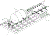
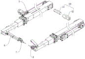
图1是实施例的立体结构示意图一。Fig. 1 is a three-dimensional structural schematic diagram of the first embodiment.

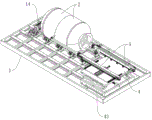
图2是实施例的立体结构示意图二。Fig. 2 is the second stereoscopic structural diagram of the embodiment.

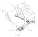
图3是实施例中焊接时第一焊枪和第二焊枪的位置状态示意图。Fig. 3 is a schematic diagram of the positions and states of the first welding torch and the second welding torch during welding in the embodiment.

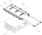
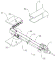
图4是实施例的剪式升降台和两个第一伸缩臂的立体结构分解图。Fig. 4 is an exploded view of the three-dimensional structure of the scissor lift platform and the two first telescopic arms of the embodiment.

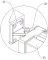
图5是图4中A处的局部结构放大图。FIG. 5 is an enlarged view of the local structure at A in FIG. 4 .

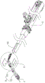
图6是实施例的两个第一伸缩臂的立体结构分解图。Fig. 6 is an exploded view of the three-dimensional structure of the two first telescopic arms of the embodiment.

图7是实施例的工业相机和第二焊枪在第一伸缩臂输出端上的位置状态图。Fig. 7 is a position diagram of the embodiment of the industrial camera and the second welding torch on the output end of the first telescopic arm.

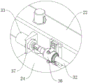
图8是实施例的第一伸缩臂和第二伸缩臂的立体结构分解图。Fig. 8 is an exploded view of the three-dimensional structure of the first telescopic arm and the second telescopic arm of the embodiment.

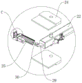
图9是图8中B处的局部结构放大图。FIG. 9 is an enlarged view of the local structure at B in FIG. 8 .

图10是图9中C处的局部结构放大图。FIG. 10 is an enlarged view of the local structure at point C in FIG. 9 .

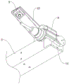
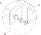
图11是实施例的两个铰接板和第二伸缩臂的立体结构分解图。Fig. 11 is an exploded view of the three-dimensional structure of the two hinge plates and the second telescopic arm of the embodiment.

图12是图11中D1处的局部结构放大图。FIG. 12 is an enlarged view of the local structure at D1 in FIG. 11 .

图13是图11中D2处的局部结构放大图。FIG. 13 is an enlarged view of the local structure at D2 in FIG. 11 .

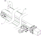
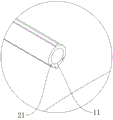
图14是实施例的第一伸缩臂的固定臂与供电内筒的立体结构分解图。Fig. 14 is an exploded view of the three-dimensional structure of the fixed arm of the first telescopic arm and the power supply inner cylinder of the embodiment.

图15是图14中E处的局部结构放大图。FIG. 15 is an enlarged view of the local structure at E in FIG. 14 .

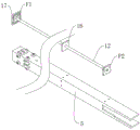
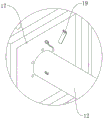
图16是实施例的第一伸缩臂的活动臂与外供电套筒的立体结构分解图。Fig. 16 is an exploded view of the three-dimensional structure of the movable arm and the outer power supply sleeve of the first telescopic arm of the embodiment.

图17是图16中F1处的局部结构放大图。FIG. 17 is an enlarged view of the partial structure at F1 in FIG. 16 .

图18是图16中F2处的局部结构放大图。Fig. 18 is an enlarged view of the partial structure at F2 in Fig. 16 .

图中标号为:1、底座;2、罐体;3、焊接载台;4、升降平台;5、第一伸缩臂;6、第二伸缩臂;7、第一焊枪;8、第二焊枪;9、工业相机;10、伸缩传动轴;11、供电内筒;12、外供电套筒;13、驱动横轴;14、双轴电机;15、承托轮;16、限位托板;17、端部封板;18、供电触片;19、金属弹片;20、绝缘连接板;21、金属供电条;22、外臂;23、内臂;24、铰接板;25、小型电缸;26、避让槽;27、第一铰接座;28、第二铰接座;29、斜铰座;30、铰接套;31、螺纹套筒;32、丝杆;33、小型电机;34、第一固定架;35、第二固定架;36、轴座;37、电机支架;38、丝杆滑台;39、滑轨;40、滑块;41、内六棱柱;42、外六棱柱套筒;43、剪式升降台;44、连接外框;45、连接支架。The labels in the figure are: 1. Base; 2. Tank body; 3. Welding platform; 4. Lifting platform; 5. First telescopic arm; 6. Second telescopic arm; 7. First welding torch; 8. Second welding torch ;9. Industrial camera; 10. Telescopic transmission shaft; 11. Power supply inner cylinder; 12. External power supply sleeve; 13. Drive horizontal shaft; 14. Dual-axis motor; 17. End sealing plate; 18. Power supply contact piece; 19. Metal shrapnel; 20. Insulation connecting plate; 21. Metal power supply strip; 22. Outer arm; 23. Inner arm; 24. Hinged plate; 25. Small electric cylinder ; 26, avoidance groove; 27, the first hinge seat; 28, the second hinge seat; 29, oblique hinge seat; 30, hinge sleeve; 31, threaded sleeve; 32, screw rod; 33, small motor; 34, the first A fixed frame; 35, the second fixed frame; 36, shaft seat; 37, motor support; 38, screw slide table; 39, slide rail; 40, slider; 41, inner hexagonal prism; 42, outer hexagonal prism sleeve Tube; 43, scissor lift table; 44, connecting outer frame; 45, connecting bracket.

具体实施方式Detailed ways

为能进一步了解本发明的特征、技术手段以及所达到的具体目的、功能,下面结合附图与具体实施方式对本发明作进一步详细描述。In order to further understand the features, technical means, and specific objectives and functions achieved by the present invention, the present invention will be further described in detail below in conjunction with the accompanying drawings and specific embodiments.

参考图1至图18所示的罐型化工设备的焊接设备,包括底座1以及设置于底座1上且用于承托并带动两个罐体2呈水平状态缓慢自转的焊接载台3,还包括设置于底座1上且位于焊接载台3旁侧的升降平台4以及呈水平状态设置于升降平台4上且用于对两个罐体2的内外交接处进行同步焊接的伸缩焊具,所述伸缩焊具包括两个相互平行间隔设置且输出端能够向焊接载台3延伸的第一伸缩臂5,其中一个第一伸缩臂5与升降平台4固连且该第一伸缩臂5的输出端上设置有能够旋转九十度的第二伸缩臂6,第二伸缩臂6的输出端上固定设置有用于焊接两罐体2连接处内圈的第一焊枪7,升降平台4上还固连有用于带动两第一伸缩臂5相互靠近或远离的平移机构,另一个第一伸缩臂5固定设置于平移机构的输出端上,且该第一伸缩臂5的输出端上固连有用于焊接两罐体2连接处外圈的第二焊枪8以及用于监测第二焊枪8焊接状态的工业相机9,两个第一伸缩臂5之间还设置有用于带动两个第一伸缩臂5输出端同步伸缩的伸缩传动轴10,每个第一伸缩臂5的固定臂和活动臂内均分别固定绝缘连接有相互电连接的供电内筒11和外供电套筒12,第二伸缩臂6和第一焊枪7与对应外供电套筒12电连接,第二焊枪8和工业相机9与对应外供电套筒12电连接。Referring to the welding equipment for tank-type chemical equipment shown in Figures 1 to 18, it includes a base 1 and a welding platform 3 arranged on the base 1 and used to support and drive two tank bodies 2 to rotate slowly in a horizontal state. It includes an elevating platform 4 arranged on the base 1 and located on the side of the welding platform 3, and a telescopic welding tool arranged horizontally on the elevating platform 4 and used for synchronous welding of the inner and outer joints of the two tank bodies 2. The telescopic welding tool includes two first telescopic arms 5 arranged parallel to each other at intervals and whose output end can extend to the welding platform 3, wherein one of the first telescopic arms 5 is fixedly connected with the lifting platform 4 and the output of the first telescopic arm 5 The end is provided with the second telescopic arm 6 that can rotate 90 degrees, and the output end of the second telescopic arm 6 is fixedly provided with the first welding torch 7 that is used for welding the inner circle of the junction of two tank bodies 2, and the lifting platform 4 is also fixed. A translation mechanism for driving the two first telescopic arms 5 to approach or move away from each other is connected, and another first telescopic arm 5 is fixedly arranged on the output end of the translation mechanism, and the output end of the first telescopic arm 5 is fixedly connected with The second welding torch 8 for welding the outer ring of the joint of the two tank bodies 2 and the industrial camera 9 for monitoring the welding state of the second welding torch 8 are also provided between the two first telescopic arms 5 for driving the two first telescopic arms 5 The telescopic transmission shaft 10 that is synchronously telescopic at the output end, the fixed arm and the movable arm of each first telescopic arm 5 are respectively fixed and insulated and connected with a power supply inner cylinder 11 and an outer power supply sleeve 12 that are electrically connected to each other, and the second telescopic arm 6 The first welding torch 7 is electrically connected to the corresponding external power supply sleeve 12 , and the second welding torch 8 and the industrial camera 9 are electrically connected to the corresponding external power supply sleeve 12 .

罐体2呈图1至图3中所示结构,且两个罐体2被放置于焊接载台3前,两个罐体2的连接处已经过多点点焊进行初固定,且其中一个罐体2靠近升降平台4的一侧成型有能够供对应第一伸缩臂5输出端伸入的开口结构,第一伸缩臂5能够带动其输出端精确伸长一定距离,焊接载台3上设置有图1和图3中所示的两根呈水平状态且能够自由旋转的驱动横轴13以及用于同步带动两根驱动横轴13同步同向旋转的双轴电机14,每根驱动横轴13上均固连有若干个间隔设置且用于承托两个罐体2的承托轮15,驱动横轴13的轴向与第一伸缩臂5的长度方向相平行,且第二伸缩臂6旋转九十度后能够使其长度方向与对应第一伸缩臂5的长度方向相垂直,两个罐体2被放置于若干个承托轮15上,其中一个第一伸缩臂5与升降平台4固连,升降平台4能够带动该第一伸缩臂5升高至与两个罐体2轴线等高度处(即两个罐体2的轴线与第一伸缩臂5沿长度方向的水平中心面和竖直中心面的交界线相重合),且安装两个驱动横轴13、升降平台4以及与升降平台4相固连的第一伸缩臂5时,保证两个驱动横轴13对称设置于该第一伸缩臂5长度方向的两侧,如此升降平台4将该第一伸缩臂5升高至与两个罐体2轴线等高度时,与升降平台4相固连的第一伸缩臂5沿其长度方向的水平中心面和竖直中心面的交界线,便与罐体2的轴线相重合(如此通过调整第二伸缩臂6的长度,即可保证第二伸缩臂6的长度方向垂直于第一伸缩臂5的长度方向时,第一焊枪7能够精确移动至贴近两罐体2内连接处的状态),通过事先测量两个罐体2连接处与升降平台4之间的间距、伸长第一伸缩臂5至合适距离、旋转第二伸缩臂6至第二伸缩臂6垂直于对应第一伸缩臂5以及合理控制第二伸缩臂6的长度,使得第一焊枪7移动至靠近两个罐体2内交接处的状态,且两个第一伸缩臂5通过伸缩传动轴10传动相连,保证两个第一伸缩臂5的输出端始终伸出相同距离,再通过平移机构的配合调整对应第一伸缩臂5的位置,即可使得第二焊枪8和工业相机9移动至靠近两个罐体2外交接处的状态,即图3中所示状态,如此,双轴电机14通过两根驱动横轴13带动若干个承托轮15同步同向旋转后即可带动罐体2缓慢旋转,配合第一焊枪7和第二焊枪8,即可实现对两个罐体2的内外交接处的同步焊接。The tank body 2 has the structure shown in Figures 1 to 3, and the two tank bodies 2 are placed in front of the welding platform 3, and the joints of the two tank bodies 2 have been initially fixed by multi-point spot welding, and one of the tank bodies The side of the body 2 close to the lifting platform 4 is formed with an opening structure that can be inserted into the output end of the corresponding first telescopic arm 5. The first telescopic arm 5 can drive its output end to extend a certain distance accurately. The welding carrier 3 is provided with The two horizontal drive shafts 13 shown in FIG. 1 and FIG. 3 and the two-axis motor 14 for synchronously driving the two drive shafts 13 to rotate synchronously and in the same direction, each drive shaft 13 There are several supporting wheels 15 arranged at intervals and used to support the two tank bodies 2. The axial direction of the driving transverse shaft 13 is parallel to the length direction of the first telescopic arm 5, and the second telescopic arm 6 After rotating 90 degrees, its length direction can be perpendicular to the length direction of the corresponding first telescopic arm 5. Two tank bodies 2 are placed on several support wheels 15, and one of the first telescopic arms 5 is connected to the lifting platform 4. Fixed connection, the lifting platform 4 can drive the first telescopic arm 5 to rise to the same height as the axis of the two tank bodies 2 (that is, the axis of the two tank bodies 2 and the horizontal center plane of the first telescopic arm 5 along the length direction and The boundary lines of the vertical center planes are coincident), and when installing the two driving horizontal shafts 13, the lifting platform 4 and the first telescopic arm 5 fixedly connected with the lifting platform 4, ensure that the two driving horizontal shafts 13 are arranged symmetrically on the Both sides of the length direction of the first telescopic arm 5, when the lifting platform 4 raised the first telescopic arm 5 to the same height as the axes of the two tank bodies 2, the first telescopic arm 5 fixedly connected with the lifting platform 4 moved along the The horizontal central plane of its length direction and the boundary line of vertical central plane just coincide with the axis of tank body 2 (by adjusting the length of the second telescopic arm 6 like this, can guarantee that the length direction of the second telescopic arm 6 is perpendicular to In the length direction of the first telescopic arm 5, the first welding torch 7 can be accurately moved to the state close to the connection in the two tanks 2), by measuring the distance between the connection of the two tanks 2 and the lifting platform 4 in advance, the extension Lengthen the first telescopic arm 5 to a suitable distance, rotate the second telescopic arm 6 to the point where the second telescopic arm 6 is perpendicular to the corresponding first telescopic arm 5 and reasonably control the length of the second telescopic arm 6, so that the first welding torch 7 moves close to the two The state of the junction in the tank body 2, and the two first telescopic arms 5 are connected through the telescopic transmission shaft 10 transmission, to ensure that the output ends of the two first telescopic arms 5 always extend the same distance, and then adjusted through the cooperation of the translation mechanism Corresponding to the position of the first telescopic arm 5, the second welding torch 8 and the industrial camera 9 can be moved to a state close to the junction of the two tank bodies 2, that is, the state shown in Fig. 3 , so that the biaxial motor 14 passes two The root driving horizontal shaft 13 drives several support wheels 15 to rotate synchronously and in the same direction to drive the tank body 2 to rotate slowly. Cooperating with the first welding torch 7 and the second welding torch 8, the internal and external joints of the two tank bodies 2 can be realized. synchronous welding.

为了保证第一伸缩臂5与供电内筒11和外供电套筒12的绝缘连接以及保持供电内筒11和外供电套筒12之间的电连接,具体设置了如下特征:In order to ensure the insulating connection between the first telescopic arm 5 and the power supply inner cylinder 11 and the outer power supply sleeve 12 and to maintain the electrical connection between the power supply inner cylinder 11 and the outer power supply sleeve 12, the following features are specifically set:

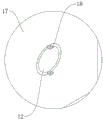
每个所述第一伸缩臂5的活动臂内均固定设置有若干个沿其长度方向等间距设置的限位托板16,且每个所述限位托板16上均开设有适应对应外供电套筒12结构的承托穿孔,每个第一伸缩臂5的活动臂两端均固连有端部封板17,且每个外供电套筒12的其中一端与对应端部封板17相固连,每个外供电套筒12靠近对应第一伸缩臂5自由端的一端均绝缘固连有两个供电触片18,每个外供电套筒12的另一端均绝缘固连有两个分别与两个供电触片18电连接的金属弹片19,每个第一伸缩臂5的固定臂远离其活动臂的一端内均固连有绝缘连接板20,绝缘连接板20与对应供电内筒11对应端绝缘固连,每个供电内筒11的另一端滑动插设于对应外供电套筒12内,每个供电内筒11上还绝缘固连有两个对称设置的金属供电条21且两个金属弹片19夹紧滑动设置于两个金属供电条21上。The movable arm of each said first telescopic arm 5 is fixedly provided with several space-limiting pallets 16 equidistantly arranged along its length direction, and each of said space-limiting pallets 16 is provided with a corresponding outer wall. The support perforation of the power supply sleeve 12 structure, the end sealing plate 17 is fixedly connected to both ends of the movable arm of each first telescopic arm 5, and one end of each outer power supply sleeve 12 is connected to the corresponding end sealing plate 17 Each outer power supply sleeve 12 is insulated and fixedly connected to one end of the free end of the corresponding first telescopic arm 5 with two power supply contacts 18, and the other end of each outer power supply sleeve 12 is insulated and fixedly connected to two power supply contacts. The metal shrapnel 19 electrically connected to the two power supply contacts 18 respectively, the fixed arm of each first telescopic arm 5 is fixedly connected with an insulating connecting plate 20 at the end of the fixed arm away from its movable arm, and the insulating connecting plate 20 is connected with the corresponding power supply inner cylinder 11 The corresponding end is insulated and fixed, and the other end of each power supply inner cylinder 11 is slidably inserted into the corresponding outer power supply sleeve 12, and each power supply inner cylinder 11 is also insulated and fixedly connected with two symmetrically arranged metal power supply bars 21 and Two metal elastic pieces 19 are clamped and slidably arranged on two metal power supply bars 21 .

为了适应罐体2的尺寸,第一伸缩臂5的长度较长而第二伸缩臂6长度较短,第一焊枪7以及第二伸缩臂6均与对应两个供电触片18电连接,从而保证第一伸缩臂5的长度改变后,第一焊枪7和第二伸缩臂6仍能够保持供电,也避免了在第一伸缩臂5内设置较长且易缠绕的供电线材,同理第二焊枪8和工业相机9与对应两个供电触片18电连接,保持随着对应第一伸缩臂5的伸长,仍能对第二焊枪8和工业相机9持续供电。In order to adapt to the size of the tank body 2, the length of the first telescopic arm 5 is longer and the length of the second telescopic arm 6 is shorter, and the first welding torch 7 and the second telescopic arm 6 are electrically connected to the corresponding two power supply contacts 18, thereby Ensure that after the length of the first telescopic arm 5 is changed, the first welding torch 7 and the second telescopic arm 6 can still maintain power supply, and it also avoids setting a long and easily entangled power supply wire in the first telescopic arm 5. Similarly, the second The welding torch 8 and the industrial camera 9 are electrically connected to the corresponding two power supply contacts 18, so that the second welding torch 8 and the industrial camera 9 can still be powered continuously as the corresponding first telescopic arm 5 is extended.

为了带动第二伸缩臂6在第一伸缩臂5的输出端上旋转以及实现第二伸缩臂6的伸缩,具体设置了如下特征:In order to drive the second telescopic arm 6 to rotate on the output end of the first telescopic arm 5 and realize the expansion and contraction of the second telescopic arm 6, the following features are specifically set:

所述第二伸缩臂6包括与第一伸缩臂5输出端相铰接的外臂22和滑动设置于外臂22内的内臂23,对应第一伸缩臂5的输出端上固连有两个对称设置的铰接板24,外臂22远离内臂23的一端铰接设置于两个铰接板24之间,且对应第一伸缩臂5的输出端上还设置有用于带动第二伸缩臂6旋转九十度的翻转机构,第二伸缩臂6上设置有用于带动内臂23相对外臂22伸缩的伸缩机构,所述翻转机构和伸缩机构均与对应两个供电触片18电连接,第一焊枪7与内臂23远离外臂22一端相固连。The second telescopic arm 6 includes an outer arm 22 hinged to the output end of the first telescopic arm 5 and an inner arm 23 slidably arranged in the outer arm 22, two corresponding to the output end of the first telescopic arm 5 are fixedly connected. Symmetrically arranged hinge plates 24, one end of the outer arm 22 away from the inner arm 23 is hingedly arranged between the two hinge plates 24, and the output end corresponding to the first telescopic arm 5 is also provided with a device for driving the second telescopic arm 6 to rotate nine times. A ten-degree turning mechanism, the second telescopic arm 6 is provided with a telescopic mechanism for driving the inner arm 23 to expand and contract relative to the outer arm 22, the turning mechanism and the telescopic mechanism are electrically connected to the corresponding two power supply contacts 18, the first welding torch 7 is fixedly connected with the end of the inner arm 23 away from the outer arm 22.

外臂22呈图8和图9中所示状态铰接设置于两个铰接板24之间,外臂22对应端固连有轴接设置于两个铰接板24上的旋转横轴,每个铰接板24上均开设有九十度弧形槽(图中未示出),且旋转横轴的两端均嵌设有分别滑动设置于两个九十度弧形槽内的平键,通过九十度弧形槽对两个平键的限位,保证外臂22对应端在翻转机构驱动下仅能旋转九十度,且外臂22带动内臂23远离对应第一伸缩臂5输出端旋转至极限位置后能够使得外臂22的长度方向与第一伸缩臂5的长度方向相垂直(即图6和图8中所示状态),此时即对应第一焊枪7对两罐体2内壁焊接的状态,而外臂22带动内臂23靠近对应第一伸缩臂5输出端旋转至极限位置后,则可保持外臂22的长度方向与第一伸缩臂5的长度方向相平行,如此方便该第一伸缩臂5带动第一焊枪7进出对应罐体2。The outer arm 22 is hingedly arranged between the two hinged plates 24 in the state shown in FIG. 8 and FIG. The plate 24 is provided with a ninety-degree arc groove (not shown in the figure), and both ends of the horizontal axis of rotation are embedded with flat keys that are slidably arranged in the two ninety-degree arc grooves. The limit of the two flat keys by the ten-degree arc groove ensures that the corresponding end of the outer arm 22 can only rotate 90 degrees under the drive of the turning mechanism, and the outer arm 22 drives the inner arm 23 to rotate away from the output end of the corresponding first telescopic arm 5 After reaching the extreme position, the length direction of the outer arm 22 can be perpendicular to the length direction of the first telescopic arm 5 (that is, the state shown in Fig. 6 and Fig. 8 ), which corresponds to the first welding torch 7 pairing the inner walls of the two tank bodies 2 In the state of welding, after the outer arm 22 drives the inner arm 23 to rotate to the extreme position close to the output end of the corresponding first telescopic arm 5, the length direction of the outer arm 22 can be kept parallel to the length direction of the first telescopic arm 5, which is so convenient The first telescopic arm 5 drives the first welding torch 7 into and out of the corresponding tank body 2 .

为了带动外臂22在对应第一伸缩臂5的输出端上翻转九十度,具体设置了如下特征:In order to drive the outer arm 22 to turn over 90 degrees on the output end corresponding to the first telescopic arm 5, the following features are specifically set:

所述翻转机构包括固定端与第一伸缩臂5输出端相铰接且与对应两个供电触片18电连接的小型电缸25,对应第一伸缩臂5的输出端上开设有用于避让小型电缸25的避让槽26,且该第一伸缩臂5的输出端上还固连有第一铰接座27,小型电缸25的缸体远离其输出端的一端固连有与第一铰接座27相铰接的第二铰接座28,外臂22远离内臂23的一端固连有斜铰座29,且小型电缸25的输出端上固连有与斜铰座29相铰接的铰接套30。The turning mechanism includes a small electric cylinder 25 whose fixed end is hinged to the output end of the first telescopic arm 5 and is electrically connected to the corresponding two power supply contacts 18, and a small electric cylinder 25 corresponding to the output end of the first telescopic arm 5 is provided for avoiding the small electric cylinder. The escape groove 26 of the cylinder 25, and the output end of the first telescopic arm 5 is also fixedly connected with the first hinged seat 27, and the end of the cylinder body of the small electric cylinder 25 away from its output end is fixedly connected with the first hinged seat 27. In the hinged second hinge seat 28 , the end of the outer arm 22 away from the inner arm 23 is fixedly connected with an oblique hinge seat 29 , and the output end of the small electric cylinder 25 is fixedly connected with a hinge sleeve 30 hinged with the oblique hinge seat 29 .

通过第一铰接座27与第二铰接座28之间以及斜铰座29与铰接套30之间的铰接配合,能够保证当小型电缸25的输出端伸出后,通过第二伸缩臂6带动第一焊枪7靠近对应第一伸缩臂5,而小型电缸25具有高精度且驱动力较大的特点,从而能够实现带动第二伸缩臂6绕旋转横轴精确旋转九十度,所述斜铰座29呈图9中所示结构,其远离外臂22一端倾斜朝向小型电缸25延伸并与铰接套30相铰接,使得小型电缸25能够更加顺畅的驱动外臂22旋转,同时当外臂22与第一伸缩臂5相平行时,保证小型电缸25的输出端不会与外臂22干涉。Through the hinge fit between the first hinge seat 27 and the second hinge seat 28 and between the oblique hinge seat 29 and the hinge sleeve 30, it can be ensured that when the output end of the small electric cylinder 25 stretches out, the second telescopic arm 6 drives The first welding gun 7 is close to the corresponding first telescopic arm 5, and the small electric cylinder 25 has the characteristics of high precision and large driving force, so that it can drive the second telescopic arm 6 to rotate precisely 90 degrees around the horizontal axis of rotation. The hinge seat 29 has the structure shown in FIG. 9 , and its end away from the outer arm 22 extends obliquely towards the small electric cylinder 25 and is hinged with the hinge sleeve 30 so that the small electric cylinder 25 can drive the outer arm 22 to rotate more smoothly. When the arm 22 is parallel to the first telescopic arm 5, it is ensured that the output end of the small electric cylinder 25 will not interfere with the outer arm 22.

为了带动内臂23在外臂22内精确伸缩,具体设置了如下特征:In order to drive the inner arm 23 to expand and contract precisely in the outer arm 22, the following features are specifically set:

所述伸缩机构包括与内臂23相固连且轴线与内臂23长度方向相平行的螺纹套筒31、同轴设置于螺纹套筒31内且与螺纹套筒31螺纹连接的丝杆32以及与外臂22固连且输出端与丝杆32同轴固连的小型电机33,内臂23远离外臂22的一端固定设置有用于与螺纹套筒31相固连的第一固定架34,外臂22靠近内臂23的一端固定设置有与螺纹套筒31滑动相连的第二固定架35,且外臂22另一端固连有用于与丝杆32远离螺纹套筒31一端轴接相连的轴座36,小型电机33为与对应两个供电触片18电连接的步进电机且小型电机33通过电机支架37与外臂22相固连。The telescoping mechanism includes a threaded sleeve 31 that is fixedly connected with the inner arm 23 and whose axis is parallel to the length direction of the inner arm 23, a screw rod 32 coaxially arranged in the threaded sleeve 31 and threaded with the threaded sleeve 31, and A small motor 33 that is fixedly connected with the outer arm 22 and whose output end is coaxially connected with the screw rod 32, and the end of the inner arm 23 away from the outer arm 22 is fixedly provided with a first fixing frame 34 for being fixedly connected with the threaded sleeve 31, One end of the outer arm 22 close to the inner arm 23 is fixedly provided with a second fixing bracket 35 slidingly connected with the threaded sleeve 31, and the other end of the outer arm 22 is fixedly connected with a shaft connection with the end of the screw rod 32 away from the threaded sleeve 31. The shaft seat 36 and the small motor 33 are stepper motors electrically connected to the corresponding two power supply contacts 18 and the small motor 33 is fixedly connected to the outer arm 22 through the motor bracket 37 .

螺纹套筒31靠近第一固定架34一端成型有图13中所示的正六棱柱结构,且正六棱柱的截面外切圆直径小于螺纹套筒31靠近外臂22一端外径,第一固定架34上开设有与正六棱柱结构相适应的棱槽,且螺纹套筒31该端还固连有两个用于将螺纹套筒31该端夹紧在第一固定架34上的螺母,如此实现将螺纹套筒31该端与第一固定架34固连且螺纹套筒31不会旋转,第二固定架35上则固连有滑动套设于螺纹套筒31外的直线轴承,保证螺纹套筒31能够沿其轴向在外臂22上顺畅滑动,而丝杆32一端螺纹连接在螺纹套筒31内,另一端通过轴座36轴接设置于外臂22上,丝杆32靠近轴座36一端成型有图12中所示的台阶结构,且轴座36另一端固连有用于与台阶结构相配合并对丝杆32轴向限位的轴套,以保证丝杆32无法沿其轴向在外臂22上移动,如此当小型电机33驱动丝杆32旋转后,丝杆32通过与螺纹套筒31的螺纹配合带动螺纹套筒31沿其轴向运动,从而带动内臂23在外臂22上滑动,小型电机33为步进电机能够保证内臂23相对外臂22伸缩的精度。The end of the threaded sleeve 31 close to the first fixing frame 34 is formed with a regular hexagonal prism structure as shown in FIG. There are grooves adapted to the structure of the regular hexagonal prism, and two nuts are fixedly connected to the end of the threaded sleeve 31 for clamping the end of the threaded sleeve 31 on the first holder 34, so that the This end of the threaded sleeve 31 is fixedly connected with the first fixed mount 34 and the threaded sleeve 31 will not rotate, and the second fixed mount 35 is fixedly connected with a linear bearing slidingly sleeved outside the threaded sleeve 31 to ensure that the threaded sleeve 31 can slide smoothly on the outer arm 22 along its axial direction, and one end of the screw rod 32 is screwed into the threaded sleeve 31, and the other end is pivotally arranged on the outer arm 22 through the shaft seat 36, and the end of the screw rod 32 is close to the shaft seat 36 The stepped structure shown in Figure 12 is formed, and the other end of the shaft seat 36 is fixedly connected with a bushing for matching with the stepped structure and axially limiting the screw rod 32, so as to ensure that the screw rod 32 cannot move along its axial direction on the outer arm. 22, so that when the small motor 33 drives the screw 32 to rotate, the screw 32 drives the threaded sleeve 31 to move along its axial direction through the thread cooperation with the threaded sleeve 31, thereby driving the inner arm 23 to slide on the outer arm 22, The small-sized motor 33 is a stepper motor, which can ensure the telescopic accuracy of the inner arm 23 relative to the outer arm 22 .

为了调整两个第一伸缩臂5之间的夹具以及保持两个第一伸缩臂5的同步伸缩,具体设置了如下特征:In order to adjust the clamp between the two first telescopic arms 5 and maintain the synchronous expansion and contraction of the two first telescopic arms 5, the following features are specifically set:

所述平移机构为与升降平台4相固连的丝杆滑台38,丝杆滑台38输出端的移动方向与第一伸缩臂5的长度方向相垂直,且对应第一伸缩臂5的固定臂与丝杆滑台38的输出端相固连,升降平台4上固连有两个对称设置且长度方向与第一伸缩臂5长度方向相垂直的滑轨39,每个所述滑轨39上均滑动设置有滑块40,与丝杆滑台38相连的第一伸缩臂5的固定臂与两个滑块40相固连,伸缩传动轴10包括与其中一个第一伸缩臂5相连的内六棱柱41和与另一个第一伸缩臂5相连的外六棱柱套筒42,外六棱柱套筒42上开设有适应六棱柱结构的内棱柱滑槽且内六棱柱41沿其长度方向滑动设置于内棱柱滑槽内。The translation mechanism is a screw slide 38 fixedly connected to the lifting platform 4. The moving direction of the output end of the screw slide 38 is perpendicular to the length direction of the first telescopic arm 5, and corresponds to the fixed arm of the first telescopic arm 5. It is fixedly connected with the output end of the screw slide table 38, and the lifting platform 4 is fixedly connected with two slide rails 39 which are arranged symmetrically and whose length direction is perpendicular to the length direction of the first telescopic arm 5, each of the slide rails 39 Sliders 40 are provided for sliding. The fixed arm of the first telescopic arm 5 connected to the screw slide 38 is fixedly connected with the two sliders 40. The hexagonal prism 41 and the outer hexagonal prism sleeve 42 connected with the other first telescopic arm 5, the outer hexagonal prism sleeve 42 is provided with an inner prism chute adaptable to the hexagonal prism structure and the inner hexagonal prism 41 is slidably set along its length direction In the inner prism chute.

两个滑轨39配合两个滑块40用于对对应第一伸缩臂5进行承重和限位,配合丝杆滑台38精确调整两个第一伸缩臂5之间的间距,从而保证第二焊枪8能够精确移动至两个罐体2的外连接处附近,第一伸缩臂5呈图6中所示结构,每个第一伸缩臂5的固定臂两端均设置有用于驱动其活动臂伸缩的传动齿轮,且两个传动齿轮通过链条传动相连,内六棱柱41与对应第一伸缩臂5上远离其活动臂一端的传动齿轮相固连,外六棱柱套筒42则与另一第一伸缩臂5上远离其活动臂一端的传动齿轮相固连,且其中一个第一伸缩臂5上还固定连接有用于驱动其中一个传动齿轮旋转的伺服电机,当伺服电机带动对应传动齿轮旋转后,两个传动齿轮之间通过链条带动同步旋转,而两个第一伸缩臂5的对应两个传动齿轮之间又通过内六棱柱41和外六棱柱套筒42传动相连,同样保持同步旋转,且丝杆滑台38调整两个第一伸缩臂5之间的间距后,内六棱柱41和外六棱柱套筒42之间能够在沿其轴向相对滑动的同时,不影响到对应两个传动齿轮之间的传动连接,如此两个第一伸缩臂5上的四个传动齿轮均能保持同步旋转,以保证两个第一伸缩臂5的活动臂始终能够同步伸缩且伸出距离一致。The two slide rails 39 cooperate with the two sliders 40 to carry out load-bearing and position-limiting for the corresponding first telescopic arm 5, and cooperate with the screw slide table 38 to accurately adjust the distance between the two first telescopic arms 5, thereby ensuring the second Welding torch 8 can accurately move to the vicinity of the outer connection of two tank bodies 2, and the first telescopic arm 5 is the structure shown in Figure 6, and the fixed arm two ends of each first telescopic arm 5 are all provided with for driving its movable arm telescopic transmission gear, and the two transmission gears are connected by chain transmission, the inner hexagonal prism 41 is fixedly connected with the transmission gear at the end of the corresponding first telescopic arm 5 away from its movable arm, and the outer hexagonal prism sleeve 42 is connected with the other first telescopic arm 5 The transmission gear at one end of the telescopic arm 5 away from its movable arm is fixedly connected, and one of the first telescopic arms 5 is also fixedly connected with a servo motor for driving one of the transmission gears to rotate. When the servo motor drives the corresponding transmission gear to rotate, , the two transmission gears are driven by a chain to rotate synchronously, and the corresponding two transmission gears of the two first telescopic arms 5 are connected to each other through an inner hexagonal prism 41 and an outer hexagonal prism sleeve 42, and also keep synchronous rotation, And after the screw slide 38 adjusts the distance between the two first telescopic arms 5, the inner hexagonal prism 41 and the outer hexagonal prism sleeve 42 can slide relative to each other along its axial direction without affecting the corresponding two The transmission connection between the transmission gears, so that the four transmission gears on the two first telescopic arms 5 can keep synchronously rotating, so as to ensure that the movable arms of the two first telescopic arms 5 can always be retracted synchronously and have the same extension distance.

为了保持升降平台4在底座1上的竖直升降,具体设置了如下特征:In order to maintain the vertical lifting of the lifting platform 4 on the base 1, the following features are specifically provided:

所述底座1上固连有位于焊接载台3旁侧的剪式升降台43,所述升降平台4呈水平状态与剪式升降台43顶部的输出端相固连。The base 1 is fixedly connected with a scissor lift platform 43 located at the side of the welding carrier 3 , and the lift platform 4 is fixedly connected with the output end of the top of the scissor lift platform 43 in a horizontal state.

剪式升降台43的底部与底座1相固连,剪式升降台43呈图4中所示结构,其内设置有用于驱动升降平台4竖直升降的伺服电机,保证升降平台4的移动精度。The bottom of the scissor lift 43 is fixedly connected to the base 1. The scissor lift 43 has the structure shown in FIG. .

为了将第二焊枪8和工业相机9固定在对应第一伸缩臂5上,具体设置了如下特征:In order to fix the second welding gun 8 and the industrial camera 9 on the corresponding first telescopic arm 5, the following features are specifically set:

对应第一伸缩臂5输出端上固连有用于与第二焊枪8相固连的连接外框44,且工业相机9通过连接支架45固定设置于对应第一伸缩臂5的输出端上。Corresponding to the output end of the first telescopic arm 5 is fixedly connected with a connection frame 44 for fixed connection with the second welding torch 8 , and the industrial camera 9 is fixedly arranged on the output end corresponding to the first telescopic arm 5 through a connecting bracket 45 .

焊接时第一焊枪7和第二焊枪8呈图3中所示状态,工业相机9时刻监控罐体2外侧第二焊枪8的焊接效果,通过对应第一伸缩臂5、第二伸缩臂6和小型电机33等的调控,来保证第一焊枪7在罐体2内移动至正对第二焊枪8的状态,并通过保持第一焊枪7和第二焊枪8的同步焊接来保证第二焊枪8的焊接效果与第一焊枪7的焊接效果一致,即保证两罐体2的内外连接处焊接效果一致。When welding, the first welding torch 7 and the second welding torch 8 are in the state shown in Fig. 3, and the industrial camera 9 always monitors the welding effect of the second welding torch 8 on the outside of the tank body 2. By corresponding to the first telescopic arm 5, the second telescopic arm 6 and The regulation and control of small motor 33 etc., to ensure that the first welding torch 7 moves to the state facing the second welding torch 8 in the tank body 2, and ensure the second welding torch 8 by keeping the synchronous welding of the first welding torch 7 and the second welding torch 8 The welding effect is consistent with the welding effect of the first welding torch 7, that is, to ensure that the welding effect of the internal and external connections of the two tank bodies 2 is consistent.

工作原理:在剪式升降台43的驱动下,升降平台4带动该第一伸缩臂5升高至与两个罐体2轴线等高度处(即两个罐体2的轴线与第一伸缩臂5沿长度方向的水平中心面和竖直中心面的交界线相重合),在事先安装两个驱动横轴13、升降平台4以及与升降平台4相固连的第一伸缩臂5时,保证两个驱动横轴13对称设置于该第一伸缩臂5长度方向的两侧,如此升降平台4将该第一伸缩臂5升高至与两个罐体2轴线等高度时(罐体2尺寸已知),与升降平台4相固连的第一伸缩臂5沿其长度方向的水平中心面和竖直中心面的交界线,便与罐体2的轴线相重合,通过事先测量两个罐体2连接处与升降平台4之间的间距、延长两个第一伸缩臂5的活动臂至合适距离、旋转第二伸缩臂6至第二伸缩臂6垂直于对应第一伸缩臂5以及合理控制第二伸缩臂6的长度,便可使得第一焊枪7移动至靠近两个罐体2内交接处的状态,两个第一伸缩臂5通过伸缩传动轴10传动相连,保证两个第一伸缩臂5的输出端始终伸出相同距离,再通过丝杆滑台38的配合即可调整对应第一伸缩臂5的位置,即可使得第二焊枪8和工业相机9移动至靠近两个罐体2外交接处的状态,如此,双轴电机14通过两根驱动横轴13带动若干个承托轮15同步同向旋转后即可带动罐体2缓慢旋转,配合第一焊枪7和第二焊枪8,即可实现对两个罐体2的内外交接处的同步焊接。Working principle: Driven by the scissor lift platform 43, the lifting platform 4 drives the first telescopic arm 5 to rise to the same height as the axes of the two tank bodies 2 (that is, the axes of the two tank bodies 2 and the first telescopic arm 5, the horizontal center plane along the length direction coincides with the boundary line of the vertical center plane), and when the two driving transverse shafts 13, the lifting platform 4 and the first telescopic arm 5 fixedly connected to the lifting platform 4 are installed in advance, it is ensured that Two driving transverse shafts 13 are symmetrically arranged on both sides of the length direction of the first telescopic arm 5, so that when the lifting platform 4 raises the first telescopic arm 5 to the same height as the axes of the two tank bodies 2 (the size of the tank body 2 Known), the first telescopic arm 5 that is fixedly connected with the lifting platform 4 along the boundary line of the horizontal center plane and the vertical center plane along its length direction coincides with the axis of the tank body 2. By measuring the two tanks in advance The distance between the joint of the body 2 and the lifting platform 4, extending the movable arms of the two first telescopic arms 5 to a suitable distance, rotating the second telescopic arm 6 until the second telescopic arm 6 is perpendicular to the corresponding first telescopic arm 5 and reasonable By controlling the length of the second telescopic arm 6, the first welding torch 7 can be moved to a state close to the junction of the two tank bodies 2, and the two first telescopic arms 5 are connected by a transmission shaft 10 to ensure that the two first The output end of the telescopic arm 5 always extends the same distance, and then the position corresponding to the first telescopic arm 5 can be adjusted through the cooperation of the screw slide 38, so that the second welding torch 8 and the industrial camera 9 can be moved close to the two tanks. The state of the junction outside the body 2, so that the biaxial motor 14 can drive the tank body 2 to rotate slowly after driving several supporting wheels 15 through two driving transverse shafts 13 to rotate in the same direction synchronously, and cooperate with the first welding torch 7 and the second The welding torch 8 can realize the synchronous welding of the inner and outer joints of the two tank bodies 2 .

以上实施例仅表达了本发明的一种或几种实施方式,其描述较为具体和详细,但并不能因此而理解为对本发明专利范围的限制。应当指出的是,对于本领域的普通技术人员来说,在不脱离本发明构思的前提下,还可以做出若干变形和改进,这些都属于本发明的保护范围。因此,本发明专利的保护范围应以所附权利要求为准。The above examples only represent one or several implementations of the present invention, and the descriptions thereof are more specific and detailed, but should not be construed as limiting the patent scope of the present invention. It should be noted that, for those skilled in the art, several modifications and improvements can be made without departing from the concept of the present invention, and these all belong to the protection scope of the present invention. Therefore, the protection scope of the patent for the present invention should be based on the appended claims.

Claims (6)

1. The welding equipment of the tank-type chemical equipment comprises a base (1) and a welding carrier (3) which is arranged on the base (1) and used for supporting and driving two tank bodies (2) to rotate slowly in a horizontal state, and is characterized in that the welding equipment also comprises a lifting platform (4) which is arranged on the base (1) and is positioned beside the welding carrier (3) and a telescopic welding tool which is arranged on the lifting platform (4) in a horizontal state and used for synchronously welding the inner joint and the outer joint of the two tank bodies (2), the telescopic welding tool comprises two first telescopic arms (5) which are arranged at intervals in parallel with each other and are capable of extending towards the welding carrier (3) at the output end, one of the first telescopic arms (5) is fixedly connected with the lifting platform (4), a second telescopic arm (6) which can rotate ninety degrees is arranged at the output end of the first telescopic arm (5), a first welding gun (7) which is used for welding the inner ring of the two tank bodies (2) is fixedly arranged at the output end of the second telescopic arm (6), a first welding gun (7) which is fixedly connected with the lifting platform (4) is also used for driving the first telescopic arm (5) to move close to the first telescopic arm (5) or the second telescopic arm (8) which is fixedly connected with the output end of the first telescopic arm (5) and is arranged at the output end of the second telescopic arm (5) and is fixedly connected with the second telescopic arm (8) which is provided with the second telescopic arm (8), a telescopic transmission shaft (10) used for driving the output ends of the two first telescopic arms (5) to synchronously stretch is further arranged between the two first telescopic arms (5), a power supply inner cylinder (11) and an outer power supply sleeve (12) which are electrically connected with each other are fixedly and insulating respectively in the fixed arm and the movable arm of each first telescopic arm (5), one end of each outer power supply sleeve (12) is electrically connected with a corresponding outer power supply sleeve (12), the second welding gun (8) and the industrial camera (9) are electrically connected with a corresponding outer power supply sleeve (12), a plurality of limit supporting plates (16) which are arranged at equal intervals along the length direction of the movable arm of each first telescopic arm (5) are fixedly arranged in the movable arm of each first telescopic arm (5), supporting perforations adapting to the structure of the corresponding outer power supply sleeve (12) are respectively arranged on each limit supporting plate (16), one end of each outer power supply sleeve (12) is fixedly connected with a corresponding end part (17), two free contact plates (18) are respectively connected with two metal contact plates (18) of each outer power supply sleeve (12) which are fixedly connected with one end of each free contact plate (18), the fixed arm of each first telescopic arm (5) is fixedly connected with an insulating connecting plate (20) in one end far away from the movable arm, the insulating connecting plate (20) is fixedly connected with the corresponding end of the corresponding power supply inner cylinder (11), the other end of each power supply inner cylinder (11) is slidably inserted into the corresponding outer power supply sleeve (12), two symmetrically arranged metal power supply strips (21) are fixedly connected with each power supply inner cylinder (11) in an insulating manner, two metal elastic sheets (19) are fixedly connected onto the two symmetrically arranged metal power supply strips (21) in a clamping manner, the second telescopic arm (6) comprises an outer arm (22) hinged with the output end of the first telescopic arm (5) and an inner arm (23) slidably arranged in the outer arm (22), two symmetrically arranged telescopic arms (24) are fixedly connected onto the output end of the corresponding first telescopic arm (5), one end of the outer arm (22) far away from the inner arm (23) is hinged between the two hinge plates (24), the output end of the corresponding first telescopic arm (5) is further provided with a telescopic mechanism for driving a second telescopic arm (6) to rotate, the second telescopic arm (6) is connected with the corresponding telescopic mechanism (18) which is electrically connected with the corresponding telescopic mechanism (18), the first welding gun (7) is fixedly connected with one end of the inner arm (23) far away from the outer arm (22).
2. The welding equipment of tank-type chemical equipment according to claim 1, wherein the turnover mechanism comprises a small electric cylinder (25) with a fixed end hinged with the output end of the first telescopic arm (5) and electrically connected with two corresponding power supply contact pieces (18), an avoidance groove (26) for avoiding the small electric cylinder (25) is formed in the output end of the corresponding first telescopic arm (5), a first hinging seat (27) is fixedly connected to the output end of the first telescopic arm (5), a second hinging seat (28) hinged with the first hinging seat (27) is fixedly connected to one end, away from the output end, of the cylinder body of the small electric cylinder (25), of the outer arm (22) is fixedly connected with an inclined hinging seat (29), and a hinging sleeve (30) hinged with the inclined hinging seat (29) is fixedly connected to the output end of the small electric cylinder (25).
3. Welding equipment for tank-type chemical equipment according to claim 1, characterized in that the telescopic mechanism comprises a threaded sleeve (31) fixedly connected with the inner arm (23) and having an axis parallel to the length direction of the inner arm (23), a screw rod (32) coaxially arranged in the threaded sleeve (31) and in threaded connection with the threaded sleeve (31), and a small motor (33) fixedly connected with the outer arm (22) and having an output end coaxially fixedly connected with the screw rod (32), one end of the inner arm (23) far away from the outer arm (22) is fixedly provided with a first fixing frame (34) fixedly connected with the threaded sleeve (31), one end of the outer arm (22) close to the inner arm (23) is fixedly provided with a second fixing frame (35) slidingly connected with the threaded sleeve (31), the other end of the outer arm (22) is fixedly connected with a shaft seat (36) for being in shaft connection with one end of the screw rod (32) far away from the threaded sleeve (31), and the small motor (33) is a stepping motor electrically connected with two corresponding power supply contact pieces (18) and the small motor (33) is fixedly connected with the outer arm bracket (22) through the motor.
4. The welding equipment of tank-type chemical equipment according to claim 1, wherein the translation mechanism is a screw rod sliding table (38) fixedly connected with the lifting platform (4), the moving direction of the output end of the screw rod sliding table (38) is perpendicular to the length direction of the first telescopic arm (5), the fixed arm corresponding to the first telescopic arm (5) is fixedly connected with the output end of the screw rod sliding table (38), two sliding rails (39) which are symmetrically arranged and are perpendicular to the length direction of the first telescopic arm (5) are fixedly connected with the lifting platform (4), sliding blocks (40) are slidably arranged on each sliding rail (39), the fixed arm of the first telescopic arm (5) connected with the screw rod sliding table (38) is fixedly connected with the two sliding blocks (40), the telescopic transmission shaft (10) comprises an inner hexagonal prism (41) connected with one first telescopic arm (5) and an outer hexagonal prism sleeve (42) connected with the other first telescopic arm (5), and the inner hexagonal prism sleeve (41) adapting to the six prismatic structure is arranged on the outer hexagonal prism sleeve (42) and is arranged in the sliding groove (41) along the length direction.
5. The welding equipment of the tank-type chemical equipment according to claim 1, wherein the base (1) is fixedly connected with a scissor type lifting platform (43) positioned beside the welding carrier (3), and the lifting platform (4) is horizontally fixedly connected with the output end at the top of the scissor type lifting platform (43).
6. The welding equipment of the tank-type chemical equipment according to claim 1, wherein a connecting outer frame (44) for fixedly connecting with the second welding gun (8) is fixedly connected to the output end of the corresponding first telescopic arm (5), and the industrial camera (9) is fixedly arranged on the output end of the corresponding first telescopic arm (5) through a connecting bracket (45).
CN202310223446.XA 2023-03-09 2023-03-09 Welding equipment for tank type chemical equipment Active CN115945838B (en)

Priority Applications (1)

Application Number Priority Date Filing Date Title
CN202310223446.XA CN115945838B (en) 2023-03-09 2023-03-09 Welding equipment for tank type chemical equipment

Applications Claiming Priority (1)

Application Number Priority Date Filing Date Title
CN202310223446.XA CN115945838B (en) 2023-03-09 2023-03-09 Welding equipment for tank type chemical equipment

Publications (2)

Publication Number Publication Date
CN115945838A CN115945838A (en) 2023-04-11
CN115945838B true CN115945838B (en) 2023-06-27

Family

ID=85892912

Family Applications (1)

Application Number Title Priority Date Filing Date
CN202310223446.XA Active CN115945838B (en) 2023-03-09 2023-03-09 Welding equipment for tank type chemical equipment

Country Status (1)

Country Link
CN (1) CN115945838B (en)

Families Citing this family (1)

* Cited by examiner, † Cited by third party
Publication number Priority date Publication date Assignee Title
CN116140885B (en) * 2023-04-23 2023-06-23 淄博市特种设备检验研究院 Glass lining reaction kettle welding device and method

Family Cites Families (6)

* Cited by examiner, † Cited by third party
Publication number Priority date Publication date Assignee Title
JP2001259852A (en) * 2000-03-22 2001-09-25 Nissan Motor Co Ltd Variable pressure device for spot welding gun
CN101244775A (en) * 2007-02-13 2008-08-20 张凤球 Assembled exterior float disc for storage tank
CN106144624B (en) * 2016-08-10 2017-08-29 杨晖伟 A kind of automatic boxing method and the mechanical hand of automatic boxing
CN112222662B (en) * 2020-10-22 2022-01-07 苏州海陆重工股份有限公司 Automatic welding device for large boiler pipeline
CN216546098U (en) * 2022-01-17 2022-05-17 青岛美联清洗设备有限公司 Inside self-cleaning equipment in carriage
CN218311660U (en) * 2022-09-02 2023-01-17 佛山市顺德区赛恩特实业有限公司 Welding gun rotating mechanism

Also Published As

Publication number Publication date
CN115945838A (en) 2023-04-11

Similar Documents

Publication Publication Date Title
CN115401353A (en) Full-automatic steel pipe welding device and welding method thereof
CN107378191B (en) A pipe fitting welding device, welding system and welding method
CN113996915B (en) A friction stir welding device with a variable speed probe
CN111168278A (en) an automatic welding machine
CN211219464U (en) Workpiece positioning device for digital welding processing
CN116810224A (en) High-efficiency automated welding device for tubular components
CN115945838A (en) Welding equipment of tank type chemical equipment
CN115922206B (en) Bellows compensator ring flange aligns processing frock
CN111843365A (en) Butt joint equipment suitable for steel pipe
CN112570504B (en) High strength anti-bending's intelligent cabinet body processing platform
CN220217390U (en) Automatic welding device
CN221171037U (en) Pipeline laying device
CN112809309A (en) Positioning and clamping device for welding round pipe steel
CN219986658U (en) Rapid alignment tool for welding automobile parts
CN118322220A (en) Intelligent welding robot
CN117733455A (en) Cylinder bottom group butt welding system, control system and control method
CN115488563A (en) An intelligent welding industrial robot
CN108971879A (en) A kind of production pipe fitting welding positioning device
CN114473158A (en) Industrial automatic electric arc welding workbench
CN115740936A (en) Spatial position adjustable frock clamp
CN219854639U (en) A convenient angle-adjustable fixture for robots
CN222002399U (en) Welding device
CN119609665B (en) A processing equipment for expansion joint collar
CN220838473U (en) Pipe cutting machine loading attachment
CN221019072U (en) A changeable operating table for electric welding machine

Legal Events

Date Code Title Description
PB01 Publication
PB01 Publication
SE01 Entry into force of request for substantive examination
GR01 Patent grant
GR01 Patent grant