CN115940503A - A joint module of double rigid wheel harmonic reducer - Google Patents
A joint module of double rigid wheel harmonic reducer Download PDFInfo
- Publication number
- CN115940503A CN115940503A CN202211580552.5A CN202211580552A CN115940503A CN 115940503 A CN115940503 A CN 115940503A CN 202211580552 A CN202211580552 A CN 202211580552A CN 115940503 A CN115940503 A CN 115940503A
- Authority
- CN
- China
- Prior art keywords
- rigid
- motor
- wave generator
- wheel
- bearing
- Prior art date
- Legal status (The legal status is an assumption and is not a legal conclusion. Google has not performed a legal analysis and makes no representation as to the accuracy of the status listed.)
- Pending
Links
Images


Classifications
-
- Y—GENERAL TAGGING OF NEW TECHNOLOGICAL DEVELOPMENTS; GENERAL TAGGING OF CROSS-SECTIONAL TECHNOLOGIES SPANNING OVER SEVERAL SECTIONS OF THE IPC; TECHNICAL SUBJECTS COVERED BY FORMER USPC CROSS-REFERENCE ART COLLECTIONS [XRACs] AND DIGESTS
- Y02—TECHNOLOGIES OR APPLICATIONS FOR MITIGATION OR ADAPTATION AGAINST CLIMATE CHANGE
- Y02P—CLIMATE CHANGE MITIGATION TECHNOLOGIES IN THE PRODUCTION OR PROCESSING OF GOODS
- Y02P70/00—Climate change mitigation technologies in the production process for final industrial or consumer products
- Y02P70/10—Greenhouse gas [GHG] capture, material saving, heat recovery or other energy efficient measures, e.g. motor control, characterised by manufacturing processes, e.g. for rolling metal or metal working
Landscapes
- Retarders (AREA)
Abstract
本发明提供了一种双刚轮谐波减速机关节模组,涉及减速机技术领域,包括波发生器、柔性轴承、柔轮、刚轮一、刚轮二、电机外壳、电机定子、电机转子、驱动板、电机后盖、前端盖及后端盖,刚轮一和刚轮二之间设有十字交叉滚子轴承,刚轮一和刚轮二的外壁分别作为十字交叉滚子轴承内圈和外圈;电机外壳固定在波发生器一端,电机转子套装固定在波发生器外,电机定子安装在电机外壳内,前端盖靠近波发生器的一侧设有与其一体成型且穿设在波发生器内孔内的通线管;波发生器和通线管之间设有第一轴承,电机后盖和波发生器之间设有第二轴承。本发明能够提高模组运动精度和稳定性,缩短模组轴线长度,满足模组小尺寸、轻重量、高转矩密度的需求。
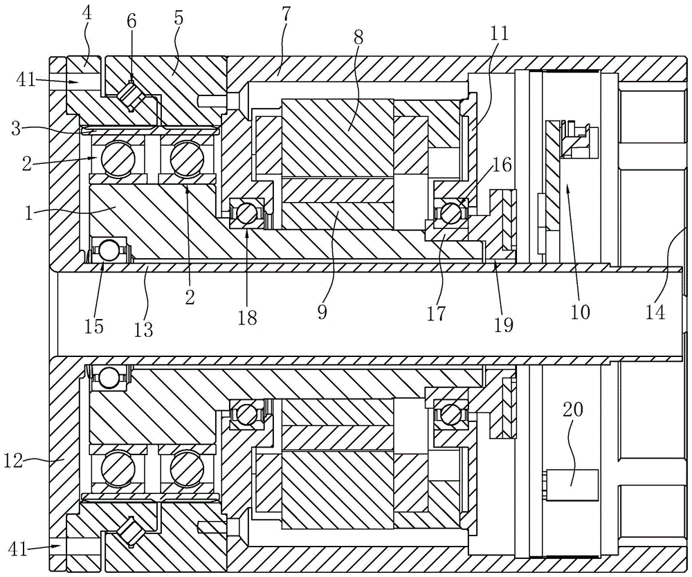
The invention provides a joint module of a double rigid wheel harmonic reducer, which relates to the technical field of reducers, including a wave generator, a flexible bearing, a flexible wheel, a rigid wheel 1, a rigid wheel 2, a motor casing, a motor stator, and a motor rotor , drive plate, motor back cover, front end cover and rear end cover, there is a cross roller bearing between the first and second steel wheels, and the outer walls of the first and second steel wheels are respectively used as the inner rings of the cross roller bearings and the outer ring; the motor casing is fixed on one end of the wave generator, the motor rotor sleeve is fixed outside the wave generator, the motor stator is installed in the motor casing, and the front end cover is integrally formed with it and pierced on the wave generator side. A line pipe in the inner hole of the generator; a first bearing is provided between the wave generator and the line pipe, and a second bearing is provided between the motor back cover and the wave generator. The invention can improve the motion precision and stability of the module, shorten the axial length of the module, and meet the requirements of small size, light weight and high torque density of the module.
Description
技术领域technical field
本发明涉及减速机技术领域,尤其涉及一种双刚轮谐波减速机关节模组。The invention relates to the technical field of reducers, in particular to a joint module of a double rigid wheel harmonic reducer.
背景技术Background technique
机器人关节模组是协作机器人、移动机器人等小型机器人的核心部件,通过减速机、电机模块化的关节模组实现机器人快速便捷的装配和维护。目前机器人关节模组正被越来越多地应用于服务类机器人行业中,因而对关节模组的小尺寸、轻重量、高转矩密度、高可靠性等性能有着严格的要求。The robot joint module is the core component of small robots such as collaborative robots and mobile robots. The joint module of the reducer and motor can realize the fast and convenient assembly and maintenance of the robot. At present, robot joint modules are being more and more used in the service robot industry, so there are strict requirements on the performance of joint modules such as small size, light weight, high torque density, and high reliability.
现有技术中的机器人关节模组多为采用单刚轮结构谐波减速机与无框力矩电机的集成化设计,单刚轮谐波减速机存在轴向长度长、负载和抗冲击能力不足等问题。而无框力矩电机受体积、厚度、中心孔径等的限制,往往转子磁性材料厚度不够,导致功率不足,无法匹配谐波减速机的输出能力,进而无法满足模组的负载能力。Most of the robot joint modules in the prior art adopt the integrated design of a single rigid wheel structure harmonic reducer and a frameless torque motor. The single rigid wheel harmonic reducer has long axial length, insufficient load and impact resistance, etc. question. The frameless torque motor is limited by volume, thickness, central aperture, etc., and the thickness of the magnetic material of the rotor is often not enough, resulting in insufficient power, which cannot match the output capacity of the harmonic reducer, and thus cannot meet the load capacity of the module.
现有技术中的双刚轮模组两个刚轮之间如不使用十字交叉轴承连接,则弯矩能力不足,无法满足模组弯矩承载能力的需求,若使用十字交叉轴承连接,则会导致体积大重量中,无法满足模组小型化轻量化需求。除此之外,现有模组中大多减速机轴和电机轴为分体式两根轴,导致两者很难做到高的同轴度,大大增加了装配难度,无法保证模组运转的平稳性。If the two rigid wheels of the double rigid wheel module in the prior art are not connected by cross bearings, the bending moment capacity is insufficient to meet the requirements of the module's bending moment carrying capacity. If the cross bearings are used to connect, it will As a result, the large volume and weight cannot meet the requirements for miniaturization and light weight of the module. In addition, most of the reducer shaft and the motor shaft in the existing modules are two separate shafts, which makes it difficult to achieve high coaxiality between the two, which greatly increases the difficulty of assembly and cannot guarantee the smooth operation of the module. sex.
发明内容Contents of the invention
本发明的目的是提供一种双刚轮谐波减速机关节模组,其能够提高模组的运动精度和稳定性,缩短模组的轴线长度,满足模组小尺寸、轻重量、高转矩密度、高可靠性的需求。The purpose of the present invention is to provide a double rigid wheel harmonic reducer joint module, which can improve the motion accuracy and stability of the module, shorten the axis length of the module, and meet the small size, light weight and high torque of the module. Density, high reliability requirements.
本发明的上述技术目的是通过以下技术方案得以实现的:Above-mentioned technical purpose of the present invention is achieved through the following technical solutions:
一种双刚轮谐波减速机关节模组,包括波发生器、柔性轴承、柔轮、刚轮一、刚轮二、电机外壳、电机定子、电机转子、驱动板、电机后盖、前端盖及后端盖,所述波发生器外安装有柔性轴承,所述柔性轴承外套装有柔轮,所述柔轮外齿与刚轮一内齿及刚轮二内齿啮合,且所述柔轮与刚轮一和刚轮二中的一个同齿啮合,另一个差齿啮合;所述刚轮一和刚轮二之间设有十字交叉滚子轴承,且所述刚轮一和刚轮二的外壁分别作为十字交叉滚子轴承的内圈和外圈,所述刚轮一的内齿和刚轮二的内齿分别在十字交叉滚子轴承的内圈和外圈上加工形成;A joint module of a double rigid wheel harmonic reducer, including a wave generator, a flexible bearing, a flexible wheel, a rigid wheel 1, a
所述电机外壳与波发生器同轴设置且固定在波发生器一端,所述刚轮二位于刚轮一和电机外壳之间且与电机外壳连接,所述电机转子套装固定在波发生器外带动波发生器旋转,所述电机定子安装在电机外壳内与电机转子配合;所述电机后盖设置在电机定子远离柔性轴承的一端,所述后端盖设置在电机外壳远离波发生器的一端,所述驱动板设置在电机后盖和后端盖之间;The motor housing is arranged coaxially with the wave generator and fixed at one end of the wave generator, the second rigid wheel is located between the first rigid wheel and the motor housing and is connected to the motor housing, and the motor rotor is set and fixed outside the wave generator Drive the wave generator to rotate, the motor stator is installed in the motor shell to cooperate with the motor rotor; the motor back cover is set at the end of the motor stator away from the flexible bearing, and the rear end cover is set at the end of the motor shell away from the wave generator , the drive board is arranged between the motor rear cover and the rear end cover;
所述前端盖设置在波发生器远离电机外壳的一端,且其靠近波发生器的一侧设有沿其轴向设置并与其一体成型的通线管,所述通线管穿设在波发生器及电机外壳的内孔内,且其与前端盖及波发生器同轴设置;所述波发生器和通线管之间设有靠近前端盖的第一轴承,所述电机后盖和波发生器之间设有第二轴承。The front end cover is arranged on the end of the wave generator away from the motor casing, and a line pipe arranged along its axial direction and integrally formed with it is provided on the side close to the wave generator, and the line pipe passes through the wave generator In the inner hole of the device and the motor casing, and it is coaxially arranged with the front end cover and the wave generator; the first bearing close to the front end cover is arranged between the wave generator and the line pipe, and the motor back cover and the wave generator A second bearing is provided between the generators.
通过采用上述技术方案,电机定子固定在电机外壳内,电机转子固定在波发生器上,刚轮二与电机外壳连接,刚轮一和刚轮二一个作为固定端,另一个作为输出端,驱动板驱动电机转子带动波发生器转动,波发生器通过柔性轴承驱动柔轮发生形变,刚轮一和刚轮二一个与柔轮齿数相同进行同齿数啮合,另一个内齿比柔轮外齿多一到四个齿进行差齿数啮合,同齿数啮合的与柔轮保持同速运转,差齿数啮合的与柔轮保持差齿数运转。利用双刚轮谐波减速机替代单刚轮谐波减速机,提高模组的抗冲击能力和负载能力。By adopting the above technical scheme, the stator of the motor is fixed in the motor casing, the rotor of the motor is fixed on the wave generator, the second rigid wheel is connected to the motor casing, one of the rigid wheel 1 and the second rigid wheel is used as a fixed end, and the other is used as an output end, The drive plate drives the motor rotor to drive the wave generator to rotate. The wave generator drives the flex spline to deform through the flexible bearing. There are one to four more teeth for differential tooth number meshing, and the meshing with the same number of teeth keeps running at the same speed with the flexspline, and the meshing with the differential number of teeth keeps running with a different number of teeth for the flexspline. The double rigid wheel harmonic reducer is used to replace the single rigid wheel harmonic reducer to improve the impact resistance and load capacity of the module.
其中,刚轮一和刚轮二分别作为十字交叉滚子轴承的内圈和外圈,且刚轮一和刚轮二的内齿均在十字交叉滚子轴承的内圈和外圈的内壁上加工所得,两者之间安装十字交叉滚子,形成刚轮一和刚轮二与十字交叉滚子轴承的一体化结构。也就是说,将原有十字交叉滚子轴承的内圈和外圈分别加工内齿替代原来的两个刚轮,在保证弯矩能力满足模组弯矩承载能力需求的同时,省去原来两个刚轮的重量和体积,而且谐波减速机的轴向长度仅相当于原来一个十字交叉滚子轴承的长度,轴向长度大幅缩短,从而有效减小模组的体积和重量,满足模组小型化、轻量化需求。Among them, the steel wheel 1 and the
另外,将波发生器的轴向长度加长,电机转子安装在波发生器外,直接将波发生器作为无框力矩电机的输入轴,提高电机和减速机的同轴度,降低装配难度,并利用第一轴承和第二轴承对减速机和电机进行支撑,保证模组运行的稳定性。而设置与前端盖一体成型的通线管,一方面便于波发生器与前端盖之间的安装,另一方面便于从通线管内走线。In addition, the axial length of the wave generator is lengthened, the motor rotor is installed outside the wave generator, and the wave generator is directly used as the input shaft of the frameless torque motor, which improves the coaxiality of the motor and the reducer, reduces the difficulty of assembly, and The reducer and the motor are supported by the first bearing and the second bearing to ensure the stability of the module operation. The provision of the line pipe integrally formed with the front end cover facilitates the installation between the wave generator and the front end cover on the one hand, and facilitates the routing of wires from the line pipe on the other hand.
本发明利用双刚轮谐波减速机替代模组中的单刚轮谐波减速机,并将波发生器作为无框力矩电机的输入轴,设置第一轴承和第二轴承对波发生器和电机进行支撑,在刚轮一和刚轮二之间设置十字交叉滚子轴承,并将刚轮一和刚轮二的外壁作为十字交叉滚子轴承的内圈和外圈,有效提高模组的运动精度和稳定性,缩短模组的轴线长度,满足模组小尺寸、轻重量、高转矩密度、高可靠性的需求。In the present invention, the double rigid wheel harmonic reducer is used to replace the single rigid wheel harmonic reducer in the module, and the wave generator is used as the input shaft of the frameless torque motor, and the first bearing and the second bearing are arranged to oppose the wave generator and the The motor is supported, and the cross roller bearing is set between the first and second steel wheels, and the outer walls of the first and second steel wheels are used as the inner and outer rings of the cross roller bearings, which effectively improves the performance of the module. Motion accuracy and stability, shorten the axis length of the module, and meet the requirements of small size, light weight, high torque density and high reliability of the module.
进一步地,所述第二轴承内圈与波发生器外圆之间设有轴承隔套,所述电机外壳靠近波发生器的一端和波发生器之间设有第三轴承;所述波发生器外圆直径呈阶梯状,其相对于轴承隔套、第三轴承、柔性轴承三个位置处的外圆直径依次增大。Further, a bearing spacer is provided between the inner ring of the second bearing and the outer circle of the wave generator, and a third bearing is provided between the end of the motor housing close to the wave generator and the wave generator; the wave generator The diameter of the outer circle of the device is stepped, and it increases sequentially relative to the diameters of the outer circle at the three positions of the bearing spacer, the third bearing and the flexible bearing.
通过采用上述技术方案,波发生器轴向长度比较长,一侧作为谐波减速机的输入轴,另一侧作为无框力矩电机的输入轴,设置第一轴承和第三轴承共同支撑减速机,第二轴承和第三轴承共同支撑电机,这样使用三个轴承合一确保整个模组的谐波减速机和电机始终能够保持同轴运转,同时减小波发生器的跳动,从而保证模组的运动精度和稳定性。其中,由于第三轴承的安装需求,波发生器外圆相对第二轴承位置处的外圆直径要小于其对应第三位置处的外圆直径,便于第三轴承从波发生器一端安装到位。而设置轴承隔套便于第二轴承的安装,且可以使得第二轴承和第三轴承大小相同,无需额外设计第二轴承。另外,波发生器外圆相对柔性轴承位置的外圆直径大于其对应第三轴承位置处的外圆直径,在保证波发生器正常功能的前提下,为电机安装提供足够的空间,并尽可能减轻波发生器的重量,满足模组的轻量化需求。By adopting the above technical scheme, the axial length of the wave generator is relatively long, one side is used as the input shaft of the harmonic reducer, and the other side is used as the input shaft of the frameless torque motor, and the first bearing and the third bearing are set to support the reducer together , the second bearing and the third bearing support the motor together, so that the use of three bearings in one ensures that the harmonic reducer and the motor of the entire module can always maintain coaxial operation, and at the same time reduce the runout of the wave generator, thereby ensuring the module movement precision and stability. Wherein, due to the installation requirements of the third bearing, the outer diameter of the outer circle of the wave generator relative to the position of the second bearing is smaller than the outer diameter of the outer circle corresponding to the third position, which is convenient for the third bearing to be installed in place from one end of the wave generator. The arrangement of the bearing spacer facilitates the installation of the second bearing, and can make the size of the second bearing and the third bearing the same, without additionally designing the second bearing. In addition, the diameter of the outer circle of the wave generator relative to the position of the flexible bearing is greater than the diameter of the outer circle corresponding to the position of the third bearing. Under the premise of ensuring the normal function of the wave generator, enough space is provided for the installation of the motor, and as much as possible Reduce the weight of the wave generator to meet the lightweight requirements of the module.
进一步地,所述驱动板和第二轴承之间设有电机编码器,所述电机编码器与波发生器靠近后端盖的一端连接;所述电机外壳内壁设有与其同轴的扭矩传感器,且所述扭矩传感器带有若干圆周阵列设置的感应片。Further, a motor encoder is provided between the drive plate and the second bearing, and the motor encoder is connected to one end of the wave generator close to the rear end cover; the inner wall of the motor housing is provided with a torque sensor coaxial with it, And the torque sensor has a plurality of induction plates arranged in a circular array.
通过采用上述技术方案,设置与波发生器连接的电机编码器,提高波发生器即输入端的转动精度,从而保证模组的运动精度。带有感应片的扭矩传感器在模组受到旋转方向的扭矩以及轴向方向的弯矩作用时会发生弹性变形,可以根据所测形变量计算模组不同方向上受到的扭矩大小,从而便于控制模组的工作。By adopting the above-mentioned technical scheme, a motor encoder connected to the wave generator is provided to improve the rotational accuracy of the wave generator, that is, the input end, thereby ensuring the motion accuracy of the module. The torque sensor with the induction sheet will elastically deform when the module is subjected to the torque in the rotation direction and the bending moment in the axial direction, and the torque received by the module in different directions can be calculated according to the measured deformation, so as to facilitate the control of the module. group work.
进一步地,所述柔性轴承设有两个,两个所述柔性轴承分别与刚轮一内齿和刚轮二内齿对应;所述刚轮一外壁作为十字交叉滚子轴承的内圈,所述刚轮二外壁作为十字交叉滚子轴承的外圈;所述刚轮一靠近前端盖的端面上和前端盖上设有相互配合的端面安装孔,且所述端面安装孔的轴线平行于刚轮一的轴线。Further, there are two flexible bearings, and the two flexible bearings correspond to the first inner tooth of the rigid wheel and the second inner tooth of the rigid wheel; the outer wall of the first rigid wheel serves as the inner ring of the cross roller bearing, so The outer wall of the second rigid wheel is used as the outer ring of the cross roller bearing; the end face of the first rigid wheel near the front end cover and the front end cover are provided with end face installation holes that cooperate with each other, and the axis of the end face installation hole is parallel to the rigid wheel. Axis of wheel one.
通过采用上述技术方案,柔性轴承设置两个且分别与刚轮一和刚轮二的内齿对应,便于波发生器通过两个柔性轴承驱动柔轮分别与刚轮一和刚轮二紧密啮合。由于刚轮一和刚轮二外形原因,将刚轮一外壁作为十字交叉滚子轴承的内圈,刚轮二作为十字交叉滚子轴承的外圈,刚轮一端面和前端盖上设置相互配合的端面安装孔,便于前端盖和刚轮一之间的安装连接。By adopting the above-mentioned technical scheme, two flexible bearings are provided and correspond to the inner teeth of the first and second rigid wheels respectively, so that the wave generator drives the flexible wheels to closely mesh with the first and second rigid wheels respectively through the two flexible bearings. Due to the shape of the steel wheel 1 and the
进一步地,所述柔性轴承设有一个且位于柔轮正中间,所述柔性轴承同时与刚轮一和刚轮二对应,所述柔轮外齿的宽度与刚轮一内齿及刚轮二内齿的总宽度一致;所述刚轮一外壁作为十字交叉滚子轴承的外圈,所述刚轮二外壁作为十字交叉滚子轴承的内圈;所述刚轮一的外壁设有外圆安装孔,且所述外圆安装孔的轴线沿刚轮一径向设置。Further, the flexible bearing is provided with one and is located in the middle of the flexible spline, the flexible bearing corresponds to the first and second rigid splines at the same time, and the width of the outer teeth of the flexible spline is the same as that of the first internal tooth of the rigid spline and the second rigid spline. The total width of the internal teeth is the same; the outer wall of the first wheel is used as the outer ring of the cross roller bearing, and the outer wall of the second wheel is used as the inner ring of the cross roller bearing; the outer wall of the first wheel is provided with an outer circle A mounting hole, and the axis of the outer circle mounting hole is arranged along the radial direction of the rigid wheel.
通过采用上述技术方案,将柔性轴承设置为一个,相应的波发生器与柔性轴承配合的椭圆凸轮、柔轮、刚轮一和刚轮二的轴向长度均可适当缩短,同时保持在轴向长度上柔轮外齿的宽度和刚轮一内齿及刚轮二内齿的总宽度一致,且柔性轴承位于柔轮正中间同时与刚轮一和刚轮二对应,这样柔轮外齿与刚轮一内齿及刚轮二内齿在啮合过程中受力程度相当,处于最优的平衡状态,减速机运转最平稳,使用寿命最大化。一个柔性轴承代替两个柔性轴承后,整个模组的体积大幅缩小,轴向长度大幅缩短,柔轮和刚轮一及刚轮二的轴向长度都缩短,这时刚轮一和包裹模组的壳体之间不再有轴向方向锁螺钉的空间,但外径没有变化,因此在刚轮一外壁设置外圆安装孔,从径向方向锁螺钉固定刚轮一和模组壳体。而由于外圆安装孔的设置及外形要求,需要将刚轮一外壁作为十字交叉滚子轴承的外圈,刚轮二外壁作为十字交叉滚子轴承的内圈。By adopting the above technical scheme, the flexible bearing is set as one, and the axial lengths of the elliptical cam, flex spline, rigid spline 1 and
进一步地,所述电机外壳与刚轮二一体成型,所述电机定子通过螺钉固定安装在刚轮二上,所述波发生器外壁设有与其同轴且与电机转子配合的环槽,所述电机转子嵌装在环槽内。Further, the motor casing and the second rigid wheel are integrally formed, the motor stator is fixed on the second rigid wheel by screws, and the outer wall of the wave generator is provided with a ring groove coaxial with it and matched with the motor rotor, so The motor rotor is embedded in the ring groove.
通过采用上述技术方案,电机外壳与刚轮二一体成型,即将电机外壳与刚轮二一体化设计,可增大整个模组的刚性和强度,并且让模组的结构更加紧凑,进一步缩短模组的轴向长度。利用螺钉将电机定子固定在刚轮二上,使得电机定子安装更加牢固,避免过盈安装带来的零件变形或者胶水固定带来的不稳定性和胶水污染问题,安装更加便捷。另外,电机定子固定在刚轮二上可以保证电机和减速机尽可能保证同轴,并且两者之间尽可能固定牢固避免产生相对位移,从而保证模组整体运行的稳定性和运动精度。而电机转子嵌装在环槽中,即将电机转子和波发生器一体化设计,一方面可以增大电机转子的厚度,提升电机的输出功率,另一方面可以使得波发生器的内孔进一步扩大,即通线管扩大,为模组接线提供便利,并且模组结构更加简单紧凑,整个模组的功率密度大幅提升。By adopting the above technical scheme, the motor shell and the rigid wheel are integrally formed, that is, the integrated design of the motor shell and the rigid wheel can increase the rigidity and strength of the entire module, and make the structure of the module more compact and further shorten The axial length of the module. The motor stator is fixed on the second rigid wheel with screws, which makes the installation of the motor stator more firm, avoids the deformation of parts caused by interference installation or the instability and glue pollution caused by glue fixing, and makes the installation more convenient. In addition, the stator of the motor is fixed on the second rigid wheel to ensure that the motor and the reducer are coaxial as much as possible, and the two are fixed as firmly as possible to avoid relative displacement, thereby ensuring the stability and motion accuracy of the overall operation of the module. The motor rotor is embedded in the ring groove, that is, the integrated design of the motor rotor and the wave generator. On the one hand, the thickness of the motor rotor can be increased, and the output power of the motor can be increased. On the other hand, the inner hole of the wave generator can be further enlarged. , that is, the expansion of the wire pipe provides convenience for module wiring, and the module structure is simpler and more compact, and the power density of the entire module is greatly improved.
进一步地,所述柔性轴承设有一个且位于柔轮正中间,所述柔性轴承同时与刚轮一和刚轮二对应,所述柔轮外齿的宽度与刚轮一内齿及刚轮二内齿的总宽度一致;所述刚轮一外壁作为十字交叉滚子轴承的外圈,所述刚轮二外壁作为十字交叉滚子轴承的内圈,且所述刚轮一的外壁设有外圆安装孔,所述外圆安装孔的轴线沿刚轮一径向设置。Further, the flexible bearing is provided with one and is located in the middle of the flexible spline, the flexible bearing corresponds to the first and second rigid splines at the same time, and the width of the outer teeth of the flexible spline is the same as that of the first internal tooth of the rigid spline and the second rigid spline. The total width of the internal teeth is the same; the outer wall of the first wheel is used as the outer ring of the cross roller bearing, the outer wall of the second wheel is used as the inner ring of the cross roller bearing, and the outer wall of the first wheel is provided with an outer ring. A circular mounting hole, the axis of the outer circular mounting hole is arranged along the radial direction of the rigid wheel.
通过采用上述技术方案,将柔性轴承设置为一个,相应的波发生器与柔性轴承配合的椭圆凸轮、柔轮、刚轮一和刚轮二的轴向长度均可适当缩短,同时保持在轴向长度上柔轮外齿的宽度和刚轮一内齿及刚轮二内齿的总宽度一致,且柔性轴承位于柔轮正中间同时与刚轮一和刚轮二对应,这样柔轮外齿与刚轮一内齿及刚轮二内齿在啮合过程中受力程度相当,处于最优的平衡状态,减速机运转最平稳,使用寿命最大化。一个柔性轴承代替两个柔性轴承后,整个模组的体积大幅缩小,轴向长度大幅缩短,柔轮和刚轮一及刚轮二的轴向长度都缩短,这时刚轮一和包裹模组的壳体之间不再有轴向方向锁螺钉的空间,但外径没有变化,因此在刚轮一外壁设置外圆安装孔,从径向方向锁螺钉固定刚轮一和模组壳体。而由于外圆安装孔的设置及外形要求,需要将刚轮一外壁作为十字交叉滚子轴承的外圈,刚轮二外壁作为十字交叉滚子轴承的内圈。By adopting the above technical scheme, the flexible bearing is set as one, and the axial lengths of the elliptical cam, flex spline, rigid spline 1 and
进一步地,所述电机转子和第二轴承之间设有第一编码器,所述驱动板和后端盖之间设有第二编码器,所述第一编码器与波发生器连接,所述第二编码器与前端盖上的通线管连接;所述电机外壳内壁设有与其同轴的扭矩传感器,且所述扭矩传感器带有若干圆周阵列设置的感应片。Further, a first encoder is provided between the motor rotor and the second bearing, a second encoder is provided between the drive plate and the rear end cover, and the first encoder is connected to the wave generator, so The second encoder is connected to the wire pipe on the front end cover; the inner wall of the motor casing is provided with a torque sensor coaxial with it, and the torque sensor has a plurality of induction plates arranged in a circular array.
通过采用上述技术方案,设置第一编码器和第二编码器,这样模组采用双编码器结构,第一编码器与波发生器即模组的输入端连接,第二编码器与通线管及模组的输出端连接,输入端和输出端双编码器闭环控制,能够大幅提升模组的运动精度。带有感应片的扭矩传感器在模组受到旋转方向的扭矩以及轴向方向的弯矩作用时会发生弹性变形,可以根据所测形变量计算模组不同方向上受到的扭矩大小,从而便于控制模组的工作。By adopting the above technical scheme, the first encoder and the second encoder are set, so that the module adopts a double encoder structure, the first encoder is connected to the wave generator, that is, the input end of the module, and the second encoder is connected to the line pipe It is connected to the output end of the module, and the closed-loop control of the double encoder at the input end and the output end can greatly improve the movement accuracy of the module. The torque sensor with the induction sheet will elastically deform when the module is subjected to the torque in the rotation direction and the bending moment in the axial direction, and the torque received by the module in different directions can be calculated according to the measured deformation, so as to facilitate the control of the module. group work.
进一步地,所述波发生器远离前端盖的一端端面和驱动板之间设有电机刹车,所述电机刹车包括衔铁、磁轭、电磁线圈和弹簧,且所述衔铁靠近波发生端面,所述电机刹车制动时,所述弹簧推动衔铁压紧波发生器端面进行刹车制动。Further, a motor brake is provided between the end face of the wave generator away from the front end cover and the drive plate, the motor brake includes an armature, a yoke, an electromagnetic coil and a spring, and the armature is close to the wave generating end face, the When the motor brakes, the spring pushes the armature to press against the end face of the wave generator for braking.
通过采用上述技术方案,原有电机刹车带有制动盘,本申请直接将波发生器的端面当做制动盘使用,省去原有制动盘,当电机刹车制动时,弹簧推动衔铁压紧波发生器端面,在摩擦力矩作用下,波发生器立即停止运转,即电机同时停止运转,实现刹车制动。这样可以减轻电机刹车的重量和体积,实现模组的轻量化和小型化。By adopting the above-mentioned technical scheme, the original motor brake has a brake disc. This application directly uses the end face of the wave generator as a brake disc, omitting the original brake disc. When the motor brakes, the spring pushes the armature to press Tighten the end face of the wave generator, under the action of friction torque, the wave generator stops running immediately, that is, the motor stops running at the same time, and the brake is realized. In this way, the weight and volume of the motor brake can be reduced, and the weight and miniaturization of the module can be realized.
进一步地,所述电机定子和刚轮二之间设有密封垫环,所述密封垫环为聚四氟乙烯垫环。Further, a sealing gasket ring is provided between the motor stator and the second rigid wheel, and the sealing gasket ring is a polytetrafluoroethylene gasket ring.
通过采用上述技术方案,设置在电机定子和刚轮二之间的密封垫环起到密封作用,防止油脂从减速机一侧泄漏至电机内。其中,密封垫环为聚四氟乙烯垫环,具有优良的化学稳定性、耐腐蚀性、密封性、高润滑不粘性、电绝缘性和良好的抗老化耐力,有效保证密封垫环的使用效果和使用寿命。By adopting the above technical solution, the gasket ring arranged between the stator of the motor and the second rigid wheel plays a sealing role, preventing grease from leaking from one side of the reducer into the motor. Among them, the gasket ring is a polytetrafluoroethylene gasket ring, which has excellent chemical stability, corrosion resistance, sealing, high lubrication and non-stickiness, electrical insulation and good anti-aging endurance, and effectively guarantees the use effect of the gasket ring and service life.
综上所述,本发明具有以下有益效果:In summary, the present invention has the following beneficial effects:
1、本发明中谐波减速机采用包括刚轮一和刚轮二的双刚轮结构替代单刚轮结构,增强谐波减速机的抗冲击能力和负载能力;刚轮一和刚轮二之间还设置十字交叉滚子轴承,且刚轮一和刚轮二的外壁分别作为十字交叉滚子轴承的内外圈,在原有十字交叉滚子轴承的内圈和外圈上加工内齿作为刚轮一和刚轮二,双刚轮与十字交叉滚子轴承一体化设计,省去原有两个刚轮的重量和体积,谐波减速机的轴向长度仅相当于原有一个十字交叉滚子轴承的长度,减速机轴向长度大幅缩短,使得整个模组更加轻量化和小型化;1. In the present invention, the harmonic speed reducer adopts a double rigid wheel structure including the first rigid wheel and the second rigid wheel to replace the single rigid wheel structure, which enhances the impact resistance and load capacity of the harmonic reducer; the difference between the first rigid wheel and the second rigid wheel Cross roller bearings are also set in the room, and the outer walls of the first and second steel wheels are respectively used as the inner and outer rings of the cross roller bearings, and the inner teeth are processed on the inner and outer rings of the original cross roller bearings as the steel wheels One and two rigid wheels, the integrated design of double rigid wheels and cross roller bearings saves the weight and volume of the original two rigid wheels, and the axial length of the harmonic reducer is only equivalent to the original cross rollers The length of the bearing and the axial length of the reducer are greatly shortened, making the whole module lighter and smaller;
2、本发明中将电机转子安装在波发生器上,加长波发生器的轴向长度,用波发生器替代原有电机输入轴,并第一轴承、第二轴承和第三轴承共同支撑减速机和电机,可大幅提升减速机和电机的同轴度,保证模组的运转精度和稳定性;2. In the present invention, the motor rotor is installed on the wave generator, the axial length of the wave generator is lengthened, the original motor input shaft is replaced by the wave generator, and the first bearing, the second bearing and the third bearing jointly support the deceleration The machine and motor can greatly improve the coaxiality of the reducer and the motor to ensure the operation accuracy and stability of the module;
3、本发明中将波发生器和电机转子一体化、电机外壳和刚轮二一体化,有效提高减速机和电机的同轴度,提高模组运转精度和平稳性,同时加大电机转子的厚度,提升电机的输出功率,整个模组的功率密度大幅提升,满足模组的负载能力需求。3. In the present invention, the wave generator and the motor rotor are integrated, and the motor casing and the rigid wheel are integrated to effectively improve the coaxiality of the reducer and the motor, improve the running accuracy and stability of the module, and increase the size of the motor rotor at the same time. The thickness of the motor increases the output power of the motor, and the power density of the entire module is greatly improved to meet the load capacity requirements of the module.
附图说明Description of drawings
图1是实施例一中一种双刚轮谐波减速机关节模组的整体结构示意图;Fig. 1 is a schematic diagram of the overall structure of a joint module of a double rigid wheel harmonic reducer in Embodiment 1;
图2是实施例二中一种双刚轮谐波减速机关节模组的整体结构示意图;Fig. 2 is a schematic diagram of the overall structure of a joint module of a double rigid wheel harmonic reducer in the second embodiment;
图3是实施例三中一种双刚轮谐波减速机关节模组的整体结构示意图;Fig. 3 is a schematic diagram of the overall structure of a joint module of a double rigid wheel harmonic reducer in the third embodiment;
图4是图3中A部分的结构示意图。FIG. 4 is a schematic structural diagram of part A in FIG. 3 .
图中,1、波发生器;2、柔性轴承;3、柔轮;4、刚轮一;41、端面安装孔;42、外圆安装孔;5、刚轮二;6、十字交叉滚子轴承;7、电机外壳;8、电机定子;81、密封垫环;82、螺钉;9、电机转子;91、环槽;10、驱动板;11、电机后盖;12、前端盖;13、通线管;14、后端盖;15、第一轴承;16、第二轴承;17、轴承隔套;18、第三轴承;19、电机编码器;20、扭矩传感器;21、第一编码器;22、第二编码器;23、电机刹车;24、衔铁;25、磁轭;26、电磁线圈;27、弹簧。In the figure, 1. wave generator; 2. flexible bearing; 3. flexible wheel; 4. rigid wheel 1; Bearing; 7. Motor shell; 8. Motor stator; 81. Gasket ring; 82. Screw; 9. Motor rotor; 91. Ring groove; 10. Drive plate; 11. Motor back cover; 12. Front cover; 13. 14. Rear end cover; 15. First bearing; 16. Second bearing; 17. Bearing spacer; 18. Third bearing; 19. Motor encoder; 20. Torque sensor; 21.
具体实施方式Detailed ways
以下结合附图和实施例,对本发明进行进一步详细说明。应当理解,此处所描述的具体实施例仅用以解释本发明,并不用于限定本发明。The present invention will be described in further detail below in conjunction with the accompanying drawings and embodiments. It should be understood that the specific embodiments described here are only used to explain the present invention, not to limit the present invention.
实施例一:Embodiment one:
一种双刚轮谐波减速机关节模组,如图1所示,包括双刚轮谐波减速机和电机,双刚轮谐波减速机包括波发生器1、柔性轴承2、柔轮3、刚轮一4、刚轮二5,电机包括电机外壳7、电机定子8、电机转子9、驱动板10、电机后盖11,电机外壳7与波发生器1同轴设置且固定在波发生器1一端,且波发生器1远离电机外壳7的一端设有前端盖12,电机外壳7远离波发生器1的一端设有后端盖14。A double rigid wheel harmonic reducer joint module, as shown in Figure 1, includes a double rigid wheel harmonic reducer and a motor, and the double rigid wheel harmonic reducer includes a wave generator 1, a
如图1所示,波发生器1与柔性轴承2对应的位置为椭圆凸轮状,柔性轴承2安装在波发生器1的椭圆凸轮上,柔性轴承2外套装环形直筒状的柔轮3,柔轮3的外齿与刚轮一4的内齿及刚轮二5的内齿同时啮合,且刚轮一4和刚轮二5其中一个内齿与柔轮3外齿齿数相同,两者同齿数啮合保持同速转动,另一个内齿比柔轮3外齿多一到四个齿,两者差齿数啮合保持差速运转。刚轮一4和刚轮二5其中一个作为输出端,另一个作为固定端。As shown in Figure 1, the position corresponding to the wave generator 1 and the
如图1所示,在刚轮一4和刚轮二5之间设有十字交叉滚子轴承6,刚轮一4和刚轮二5的外壁分别作为十字交叉滚子轴承6的内圈和外圈,且刚轮一4和刚轮二5的内齿分别在十字交叉滚子轴承6的内圈和外圈上加工形成,使得刚轮一4和刚轮二5与十字交叉滚子轴承6一体化。也就是说,直接在原来的十字交叉滚子轴承6的内外圈上分别上加工与柔轮3啮合的外齿,使十字交叉滚子轴承6的内外圈可以直接替代原有的两个刚轮,这样节省两个刚轮的体积和重量,且大幅缩小双刚轮谐波减速机的轴向长度。As shown in Figure 1, a
如图1所示,在本实施例中,柔性轴承2设有两个,两个柔性轴承2分别与刚轮一4内齿和刚轮二5内齿对应,保证柔轮3与刚轮一4及刚轮二5的啮合效果。刚轮一4外壁作为十字交叉滚子轴承6的内圈,刚轮二5外壁作为十字交叉滚子轴承6的外圈,也就是十字交叉滚子轴承6的内圈加工内齿当作刚轮一4,十字交叉滚子轴承6的外圈加工内齿当作刚轮二5。基于此结构,为方便刚轮一4与模组壳体(图中未表示)的连接,在刚轮一4靠近前端盖12的端面上和前端盖12上设有相互配合的端面安装孔41,且端面安装孔41的轴线平行于刚轮一4的轴线。As shown in Figure 1, in this embodiment, two
如图1所示,在本实施例中,刚轮二5位于刚轮一4和电机外壳7之间且与电机外壳7连接,波发生器1的轴向长度加长,电机转子9套转固定安装在波发生器1外,电机定子8安装在电机外壳7内与电机转子9配合。电机后盖11设置在电机定子8远离柔性轴承2的一端,后端盖14设置在电机外壳7远离波发生器1的一端,驱动板10设置在电机后盖11和后端盖14之间,驱动电机转子9带动波发生器1旋转。其中,前端盖12靠近波发生器1的一侧设有沿其轴向设置并与其一体成型的中空通线管13,通线管13穿设在波发生器1及电机外壳7的内孔内,且其与与前端盖12及波发生器1同轴设置,不仅方便波发生器1与前端盖12之间的转动连接,而且便于谐波减速机的穿线。As shown in Figure 1, in this embodiment, the second
如图1所示,这样通过加长波发生器1的轴向长度,电机转子9安装在波发生器1上,一侧作为谐波减速机的输入轴,另一侧作为电机的输入轴,利用波发生器1代替电机的输入轴,提高谐波减速机与电机的同轴度,降低装配难度。波发生器1轴向长度加长后运转时容易跳动,因此,在波发生器1和通线管13之间设有靠近前端盖12的第一轴承15,电机后盖11和波发生器1之间设有第二轴承16,且第二轴承16内圈和波发生器1外圆之间设有轴承隔套17,电机外壳7靠近波发生器1的一端和波发生器1之间设有第三轴承18。第一轴承15、第二轴承16和第三轴承18均为高精度深沟球轴承,这样利用第一轴承15和第三轴承18支撑波发生器1,第二轴承16和第三轴承18支撑电机,保证同轴度的同时减少波发生器1轴向跳动,提高模组运转的稳定性。As shown in Figure 1, by lengthening the axial length of the wave generator 1, the motor rotor 9 is installed on the wave generator 1, one side is used as the input shaft of the harmonic reducer, and the other side is used as the input shaft of the motor. The wave generator 1 replaces the input shaft of the motor, improves the coaxiality between the harmonic reducer and the motor, and reduces assembly difficulty. Wave generator 1 is easy to jump when running after the axial length is lengthened, therefore, be provided with the
如图1所示,在本实施例中,波发生器1外圆直径呈阶梯状,其相对于轴承隔套17、第三轴承18、柔性轴承2三个位置处的外圆直径依次增大,这样在保证波发生器1整体工作性能的同时,为电机留下足够的安装空间,同时降低模组的整体重量和体积。As shown in Figure 1, in this embodiment, the diameter of the outer circle of the wave generator 1 is stepped, and its outer circle diameter at three positions of the bearing
如图1所示,在驱动板10和第二轴承16之间还设有电机编码器19,且电机编码器19与波发生器1靠近后端盖14的一端连接,利用电机编码器19精确控制波发生器1即输入端的运转精度。另外,在电机外壳7内壁设有与其同轴的扭矩传感器20,且扭矩传感器20带有若干圆周阵列设置的感应片。带有感应片的扭矩传感器20在模组受到旋转方向的扭矩以及轴向方向的弯矩作用时会发生弹性变形,可以根据所测形变量计算模组不同方向上受到的扭矩大小,从而便于控制模组的工作。As shown in Figure 1, a
实施例二:Embodiment two:
一种双刚轮谐波减速机关节模组,如图1和图2所示,其结构及原理与实施例一中基本相同,与实施例一的而不同之处在于,柔性轴承2设有只设有一个,柔性轴承2由两个变为一个,相应地波发生器1上安装柔性轴承2的椭圆凸轮、柔轮3、刚轮一4和刚轮二5的轴向长度均可适当缩短。柔性轴承2设为一个后,要求柔性轴承2位于柔轮3正中间且同时与刚轮一4和刚轮二5对应,并且柔轮3外齿的宽度与刚轮一4内齿及刚轮二5内齿的总宽度一致,这样柔轮3外齿与刚轮一4内齿及刚轮二5内齿在啮合过程中受力程度相当,处于最优的平衡状态,减速机运转最平稳,使用寿命最大化。A double rigid wheel harmonic reducer joint module, as shown in Figure 1 and Figure 2, its structure and principle are basically the same as in Embodiment 1, the difference from Embodiment 1 is that the
如图1和图2所示,一个柔性轴承2代替两个柔性轴承2后,整个模组的体积大幅缩小,轴向长度大幅缩短,柔轮3和刚轮一4及刚轮二5的轴向长度都缩短,这时刚轮一4和包裹模组的壳体(图中未表示)之间不再有轴向方向锁螺钉82的空间,但外径没有变化,因此在刚轮一4外壁设置轴线沿刚轮一4径向设置的外圆安装孔42,用外圆安装孔42代替实施例一中的端面安装孔41,从径向方向锁螺钉82固定刚轮一4和模组壳体。As shown in Figure 1 and Figure 2, after one
如图1和图2所示,而由于外圆安装孔42的设置及外形要求,需要将刚轮一4外壁作为十字交叉滚子轴承6的外圈,刚轮二5外壁作为十字交叉滚子轴承6的内圈,相当于将实施例一中的刚轮一4和刚轮二5外形调换,也就是说,在十字交叉滚子轴承6的外圈上加工内齿当作刚轮一4使用,在十字交叉滚子轴承6的内圈上加工内齿当作刚轮二5使用。As shown in Figure 1 and Figure 2, due to the setting and shape requirements of the outer circular mounting
实施例三:Embodiment three:
一种双刚轮谐波减速机关节模组,其基本结构和原理与实施例一中基本相同,不同之处在于:A double rigid wheel harmonic reducer joint module, its basic structure and principle are basically the same as those in Embodiment 1, the difference lies in:
如图1和图3所示,实施例一中电机与刚轮二5可拆卸安装连接,电机转子9直接套装固定在波发生器1外,而本实施例中,将电机外壳7与刚轮二5设置为一体成型,电机定子8通过螺钉82固定安装在刚轮二5上,波发生器1外壁设有与其同轴且与电机转子9配合的环槽91,电机转子9嵌装在环槽91内,也就是说,本实施例中电机外壳7和刚轮二5一体化设计,电机转子9和波发生器1一体化设计。As shown in Fig. 1 and Fig. 3, in embodiment one, the motor is detachably installed and connected to the
如图1和图3所示,电机外壳7和刚轮的一体化设计能够增大整个模组的刚性和强度,让模组的结构更加紧凑,进一步缩短模组的轴向长度。利用螺钉82将电机定子8固定在刚轮二5上,使得电机定子8安装更加牢固,避免过盈安装带来的零件变形或者胶水固定带来的不稳定性和胶水污染问题,安装更加便捷。另外,电机定子8固定在刚轮二5上可以保证电机和减速机尽可能保证同轴,并且两者之间尽可能固定牢固避免产生相对位移,从而保证模组整体运行的稳定性和运动精度。As shown in Figures 1 and 3, the integrated design of the motor housing 7 and the rigid wheel can increase the rigidity and strength of the entire module, make the structure of the module more compact, and further shorten the axial length of the module. Use screws 82 to fix the
如图1和图3所示,电机转子9和波发生器1一体化设计,一方面可以增大电机转子9的厚度,提升电机的输出功率,另一方面可以使得波发生器1的内孔进一步扩大,即通线管13扩大,为模组接线提供便利,并且模组结构更加简单紧凑,整个模组的功率密度大幅提升。As shown in Figures 1 and 3, the integrated design of the motor rotor 9 and the wave generator 1 can increase the thickness of the motor rotor 9 on the one hand and increase the output power of the motor, and on the other hand can make the inner hole of the wave generator 1 Further expansion, that is, the expansion of the
如图1和图3所示,由于本实施例中刚轮二5和电机外壳7一体化设计,所以取消波发生器1和电机外壳7之间的第三轴承18以及第二轴承16和波发生器1之间的轴承隔套17。另外,如图3所示,刚轮二5和电机外壳7一体化设计后,为避免泄漏,在电机定子8和刚轮二5之间设有密封垫环81,且密封垫环81为聚四氟乙烯垫环,防止油脂从减速机一侧泄漏至电机内。As shown in Fig. 1 and Fig. 3, due to the integrated design of
本实施例中柔性轴承2只设置有一个,替代实施例一中两个,如图2和图3所示,与实施例二中相同,单个柔性轴承2位于柔轮3正中间且同时与与刚轮一4和刚轮二5对应,柔轮3外齿的宽度与刚轮一4内齿及刚轮二5内齿的总宽度一致。同样地,在刚轮一4外壁设置轴线沿刚轮一4径向设置的外圆安装孔42,用外圆安装孔42代替实施例一中的端面安装孔41,从径向方向锁螺钉82固定刚轮一4和模组壳体。而由于外圆安装孔42的设置及外形要求,将刚轮一4外壁作为十字交叉滚子轴承6的外圈,刚轮二5外壁作为十字交叉滚子轴承6的内圈,相当于将实施例一中的刚轮一4和刚轮二5外形调换,也就是说,在十字交叉滚子轴承6的外圈上加工内齿当作刚轮一4使用,在十字交叉滚子轴承6的内圈上加工内齿当作刚轮二5使用。In this embodiment, there is only one
如图1和图3所示,本实施例中与实施例一中一样,电机外壳7内壁设有与其同轴的扭矩传感器20,且扭矩传感器20带有若干圆周阵列设置的感应片,利用扭矩传感器20所测形变量计算模组不同方向上受到的扭矩大小,从而便于控制模组的工作。As shown in Figures 1 and 3, in this embodiment, as in Embodiment 1, the inner wall of the motor housing 7 is provided with a
如图1和图3所示,不同的是,本实施例中编码器设有两个,替代实施例一中的一个电机编码器19。在电机转子9和第二轴承16之间设有第一编码器21,驱动板10和后端盖14之间设有第二编码器22,第一编码器21与波发生器1连接,第二编码器22与前端盖12上的通线管13连接。这样模组采用双编码器结构,第一编码器21与波发生器1即模组的输入端连接,第二编码器22与通线管13即模组的输出端连接,输入端和输出端双编码器闭环控制,能够大幅提升模组的运动精度。As shown in FIG. 1 and FIG. 3 , the difference is that there are two encoders in this embodiment, instead of one
如图3和图4所示,在本实施例中,波发生器1远离前端盖12的一端端面和驱动板10之间设有电机刹车23,电机刹车23包括衔铁24、磁轭25、电磁线圈26和弹簧27,且衔铁24靠近波发生端面,电机刹车23制动时,弹簧27推动衔铁24压紧波发生器1端面进行刹车制动。原有电机刹车23带有制动盘,本实施例中直接将波发生器1的端面当做制动盘使用,只要波发生器1端面加工处理达到原来制动盘的使用性能即可。当电机刹车23制动时,弹簧27推动衔铁24压紧波发生器1端面,在摩擦力矩作用下,波发生器1立即停止运转,即电机同时停止运转,实现刹车制动。这样省去原有制动盘,可以减轻电机刹车23的重量和体积,实现模组的轻量化和小型化。As shown in Figures 3 and 4, in this embodiment, a
上述说明示出并描述了本发明的优选实施例,如前所述,应当理解本发明并非局限于本文所披露的形式,不应看作是对其他实施例的排除,而可用于各种其他组合、修改和环境,并能够在本文所述发明构想范围内,通过上述教导或相关领域的技术或知识进行改动。而本领域人员所进行的改动和变化不脱离本发明的精神和范围,则都应在本发明所附权利要求的保护范围内。The foregoing description shows and describes preferred embodiments of the present invention, and as previously stated, it is to be understood that the present invention is not limited to the form disclosed herein and should not be construed as excluding other embodiments but may be applied to various other embodiments. Combinations, modifications and circumstances, and can be modified within the scope of the inventive concept described herein, by the above teachings or by skill or knowledge in the relevant field. However, changes and changes made by those skilled in the art do not depart from the spirit and scope of the present invention, and should all be within the protection scope of the appended claims of the present invention.
Claims (10)
Priority Applications (1)
| Application Number | Priority Date | Filing Date | Title |
|---|---|---|---|
| CN202211580552.5A CN115940503A (en) | 2022-12-09 | 2022-12-09 | A joint module of double rigid wheel harmonic reducer |
Applications Claiming Priority (1)
| Application Number | Priority Date | Filing Date | Title |
|---|---|---|---|
| CN202211580552.5A CN115940503A (en) | 2022-12-09 | 2022-12-09 | A joint module of double rigid wheel harmonic reducer |
Publications (1)
| Publication Number | Publication Date |
|---|---|
| CN115940503A true CN115940503A (en) | 2023-04-07 |
Family
ID=86651863
Family Applications (1)
| Application Number | Title | Priority Date | Filing Date |
|---|---|---|---|
| CN202211580552.5A Pending CN115940503A (en) | 2022-12-09 | 2022-12-09 | A joint module of double rigid wheel harmonic reducer |
Country Status (1)
| Country | Link |
|---|---|
| CN (1) | CN115940503A (en) |
Cited By (6)
| Publication number | Priority date | Publication date | Assignee | Title |
|---|---|---|---|---|
| CN116247874A (en) * | 2023-05-06 | 2023-06-09 | 哈尔滨艾拓普科技有限公司 | Cycloid differential driving module |
| CN117895719A (en) * | 2023-07-28 | 2024-04-16 | 南京科迈德机器人技术有限公司 | Servo deceleration module with overload protection function and overload protection method |
| CN118342535A (en) * | 2024-04-28 | 2024-07-16 | 江淮前沿技术协同创新中心 | Motion control system of robot flexible joint module based on dual encoders |
| CN120462683A (en) * | 2025-07-10 | 2025-08-12 | 北京理工大学长三角研究院(嘉兴) | Torque balancing device, turntable and aircraft |
| CN121025136A (en) * | 2025-10-30 | 2025-11-28 | 珠海市钧兴机电有限公司 | Combined harmonic reducer module, joint module and robot |
| CN121408430A (en) * | 2025-12-29 | 2026-01-27 | 深圳市杉川谐波传动科技有限公司 | Harmonic reducer and joint module |
Citations (9)
| Publication number | Priority date | Publication date | Assignee | Title |
|---|---|---|---|---|
| CN104832605A (en) * | 2015-05-11 | 2015-08-12 | 上海鑫君传动科技有限公司 | High-output torque harmonic speed reducer |
| CN106230186A (en) * | 2016-08-15 | 2016-12-14 | 广州市昊志机电股份有限公司 | A kind of set has the hollow type harmonic speed reducer of motor |
| CN107263527A (en) * | 2017-06-30 | 2017-10-20 | 东南大学 | A kind of joint arrangement for articulated robot |
| CN109366480A (en) * | 2018-12-19 | 2019-02-22 | 浙江双环传动机械股份有限公司 | A kind of dynamoelectric controlled integrated joint of robot mould group of high integration |
| CN110242710A (en) * | 2019-06-05 | 2019-09-17 | 南通振康机械有限公司 | A kind of double firm gear harmonic wave speed reducing machines of no Internal and external cycle needle-type flexible bearing integral type |
| CN111473101A (en) * | 2020-05-27 | 2020-07-31 | 苏州绿的谐波传动科技股份有限公司 | A cup-shaped harmonic reducer device for joint modules |
| CN114060495A (en) * | 2021-11-18 | 2022-02-18 | 南通振康机械有限公司 | Harmonic speed reducer with double rigid wheels |
| CN115296481A (en) * | 2022-09-13 | 2022-11-04 | 江苏开璇智能科技有限公司 | Double-rigid-wheel hollow harmonic speed reduction all-in-one machine |
| CN219458828U (en) * | 2022-12-09 | 2023-08-01 | 南通振康机械有限公司 | Double-rigid-wheel harmonic reducer joint module |
-
2022
- 2022-12-09 CN CN202211580552.5A patent/CN115940503A/en active Pending
Patent Citations (9)
| Publication number | Priority date | Publication date | Assignee | Title |
|---|---|---|---|---|
| CN104832605A (en) * | 2015-05-11 | 2015-08-12 | 上海鑫君传动科技有限公司 | High-output torque harmonic speed reducer |
| CN106230186A (en) * | 2016-08-15 | 2016-12-14 | 广州市昊志机电股份有限公司 | A kind of set has the hollow type harmonic speed reducer of motor |
| CN107263527A (en) * | 2017-06-30 | 2017-10-20 | 东南大学 | A kind of joint arrangement for articulated robot |
| CN109366480A (en) * | 2018-12-19 | 2019-02-22 | 浙江双环传动机械股份有限公司 | A kind of dynamoelectric controlled integrated joint of robot mould group of high integration |
| CN110242710A (en) * | 2019-06-05 | 2019-09-17 | 南通振康机械有限公司 | A kind of double firm gear harmonic wave speed reducing machines of no Internal and external cycle needle-type flexible bearing integral type |
| CN111473101A (en) * | 2020-05-27 | 2020-07-31 | 苏州绿的谐波传动科技股份有限公司 | A cup-shaped harmonic reducer device for joint modules |
| CN114060495A (en) * | 2021-11-18 | 2022-02-18 | 南通振康机械有限公司 | Harmonic speed reducer with double rigid wheels |
| CN115296481A (en) * | 2022-09-13 | 2022-11-04 | 江苏开璇智能科技有限公司 | Double-rigid-wheel hollow harmonic speed reduction all-in-one machine |
| CN219458828U (en) * | 2022-12-09 | 2023-08-01 | 南通振康机械有限公司 | Double-rigid-wheel harmonic reducer joint module |
Cited By (11)
| Publication number | Priority date | Publication date | Assignee | Title |
|---|---|---|---|---|
| CN116247874A (en) * | 2023-05-06 | 2023-06-09 | 哈尔滨艾拓普科技有限公司 | Cycloid differential driving module |
| CN116247874B (en) * | 2023-05-06 | 2023-08-11 | 哈尔滨艾拓普科技有限公司 | Cycloid differential driving module |
| CN117895719A (en) * | 2023-07-28 | 2024-04-16 | 南京科迈德机器人技术有限公司 | Servo deceleration module with overload protection function and overload protection method |
| CN117895719B (en) * | 2023-07-28 | 2024-08-06 | 南京科迈德机器人技术有限公司 | Servo deceleration module with overload protection function and overload protection method |
| CN118342535A (en) * | 2024-04-28 | 2024-07-16 | 江淮前沿技术协同创新中心 | Motion control system of robot flexible joint module based on dual encoders |
| CN120462683A (en) * | 2025-07-10 | 2025-08-12 | 北京理工大学长三角研究院(嘉兴) | Torque balancing device, turntable and aircraft |
| CN120462683B (en) * | 2025-07-10 | 2025-09-23 | 北京理工大学长三角研究院(嘉兴) | Moment balancing device, turntable and aircraft |
| CN121025136A (en) * | 2025-10-30 | 2025-11-28 | 珠海市钧兴机电有限公司 | Combined harmonic reducer module, joint module and robot |
| CN121025136B (en) * | 2025-10-30 | 2026-01-27 | 珠海市钧兴机电有限公司 | Combined harmonic reducer module, joint module and robot |
| CN121408430A (en) * | 2025-12-29 | 2026-01-27 | 深圳市杉川谐波传动科技有限公司 | Harmonic reducer and joint module |
| CN121408430B (en) * | 2025-12-29 | 2026-02-27 | 深圳市杉川谐波传动科技有限公司 | Harmonic reducer and joint module |
Similar Documents
| Publication | Publication Date | Title |
|---|---|---|
| CN206738541U (en) | Robot, joint of robot and its harmonic speed reducer | |
| CN108036034B (en) | Bidirectional output type harmonic speed reducer | |
| CN115008497A (en) | Compact robot joint module based on harmonic speed reducer | |
| CN109968398B (en) | Ultra-thin type external rotor harmonic speed reduction all-in-one | |
| CN106230186A (en) | A kind of set has the hollow type harmonic speed reducer of motor | |
| CN111409097B (en) | Compact joint driving device for robot | |
| CN110666836A (en) | Arm integrated joint for bidirectional output humanoid robot | |
| CN113894837A (en) | Joint power unit and mechanical arm applying same | |
| CN106300795B (en) | A kind of big retarding is than harmonic reduction all-in-one machine | |
| CN211557070U (en) | Outer rotor planetary reduction steering engine and robot | |
| CN219458828U (en) | Double-rigid-wheel harmonic reducer joint module | |
| US20070152522A1 (en) | Rotating Electrical Machine with a Transmission and a Driving Apparatus Using the Same | |
| CN114810951A (en) | A brushless outer rotor actuator for robots with built-in reducer | |
| CN112460226B (en) | A harmonic reducer and driver | |
| CN118269141B (en) | A cycloid pinwheel reduction type robot joint module and its assembly method | |
| CN117458769B (en) | A motor and integrated joint with integrated wave generator | |
| CN216299344U (en) | Joint power unit and mechanical arm applying same | |
| CN207010448U (en) | A kind of screw-nut transmission for directly driving screw | |
| CN111590553B (en) | A harmonic reducer and driver | |
| CN115580078A (en) | Integrated brushless speed reduction type hub motor | |
| CN223369452U (en) | Servo joint and robot | |
| CN118855962A (en) | A lightweight RV reducer module | |
| CN222627822U (en) | Robot joints | |
| CN111237414A (en) | Ball-driven hub speed reducer | |
| CN221487506U (en) | Harmonic gear drive motor |
Legal Events
| Date | Code | Title | Description |
|---|---|---|---|
| PB01 | Publication | ||
| PB01 | Publication | ||
| SE01 | Entry into force of request for substantive examination | ||
| SE01 | Entry into force of request for substantive examination |