CN115918711A - A shell tail removal device for snails - Google Patents
A shell tail removal device for snails Download PDFInfo
- Publication number
- CN115918711A CN115918711A CN202211491792.8A CN202211491792A CN115918711A CN 115918711 A CN115918711 A CN 115918711A CN 202211491792 A CN202211491792 A CN 202211491792A CN 115918711 A CN115918711 A CN 115918711A
- Authority
- CN
- China
- Prior art keywords
- snail
- tail
- snails
- type screw
- conveyor
- Prior art date
- Legal status (The legal status is an assumption and is not a legal conclusion. Google has not performed a legal analysis and makes no representation as to the accuracy of the status listed.)
- Pending
Links
Images


Classifications
-
- Y—GENERAL TAGGING OF NEW TECHNOLOGICAL DEVELOPMENTS; GENERAL TAGGING OF CROSS-SECTIONAL TECHNOLOGIES SPANNING OVER SEVERAL SECTIONS OF THE IPC; TECHNICAL SUBJECTS COVERED BY FORMER USPC CROSS-REFERENCE ART COLLECTIONS [XRACs] AND DIGESTS
- Y02—TECHNOLOGIES OR APPLICATIONS FOR MITIGATION OR ADAPTATION AGAINST CLIMATE CHANGE
- Y02A—TECHNOLOGIES FOR ADAPTATION TO CLIMATE CHANGE
- Y02A40/00—Adaptation technologies in agriculture, forestry, livestock or agroalimentary production
- Y02A40/80—Adaptation technologies in agriculture, forestry, livestock or agroalimentary production in fisheries management
- Y02A40/81—Aquaculture, e.g. of fish
Landscapes
- Screw Conveyors (AREA)
Abstract
本发明公开了一种螺蛳的壳尾去除装置,涉及螺蛳加工专用设备。包括安装箱、加料箱、传送机、归置器、剪切组件和收集框。其中,加料箱中设有往复落料机构,用于将加料箱中的螺蛳进行水平往复振动处理,以使螺蛳均匀地落下;传送机上设有多个排列组合的贯通式置螺槽,用于接收从加料箱中掉落下来的螺蛳;归置器用于将传送机表面上未完全落入在贯通式置螺槽中的螺蛳拨动归置在贯通式置螺槽中;剪切组件用于对贯通式置螺槽中的螺蛳尾部进行剪切。本发明解决了传统的去尾机只能对定向布置的螺蛳尾部剪除的问题,提高了生产效率;且落料均匀,能有效的防止落料时堵塞现象的出现。
The invention discloses a device for removing shell tails of snails, and relates to special equipment for processing snails. Includes mounting bins, feeding bins, conveyors, accumulators, shear assemblies and collection boxes. Among them, a reciprocating feeding mechanism is provided in the feeding box, which is used to perform horizontal reciprocating vibration treatment on the snails in the feeding box, so that the snails fall evenly; the conveyor is provided with a plurality of arranged and combined through-type screw slots for Receive the snails falling from the feeding box; the resetter is used to move the snails that have not completely fallen into the through-type screw groove on the surface of the conveyor to be placed in the through-type screw groove; the shearing assembly is used for Cut the tail of the snail in the through-type screw groove. The invention solves the problem that the traditional tail-removing machine can only cut off the snail tails arranged in a certain direction, improves the production efficiency; and the blanking is even, which can effectively prevent the occurrence of clogging during blanking.
Description
技术领域technical field
本发明涉及螺蛳加工专用设备,更具体地说,它涉及一种螺蛳的壳尾去除装置。The invention relates to special equipment for processing snails, more specifically, it relates to a device for removing shell tails of snails.
背景技术Background technique
螺蛳是一种重要的水产底栖动物,除对水环境有净化和保护作用外,还可以食用。螺蛳价廉物美,营养价值也颇高。现代科学证明,螺蛳营养素成份较全面,其中每百克含蛋白质11.4克、脂肪3.8克、碳水化合物1.5克;另外,还含有无机盐、维生素A、硫黄素、尼克酸等。因此,螺蛳的作为食品的需求量也越来越大。食用前需要对螺蛳进行去尾处理,以便清除尾部杂质,方便食用。所以需要用到螺蛳去尾机。Snail is an important aquatic benthic animal, which can be eaten in addition to purifying and protecting the water environment. Snails are cheap and good in quality, and have high nutritional value. Modern science has proved that snails have comprehensive nutrients, including 11.4 grams of protein, 3.8 grams of fat, and 1.5 grams of carbohydrates per 100 grams; in addition, they also contain inorganic salts, vitamin A, thioflavin, niacin, etc. Therefore, the demand for snails as food is also increasing. It is necessary to remove the tail of the snail before eating, so as to remove the impurities in the tail and make it easier to eat. So you need to use the snail tail removal machine.
从螺蛳去尾机的现状来看,目前的螺蛳去尾机有滚筒式的去尾机,如公开号为CN210580759U的一种螺蛳去尾机,其通过滚筒将螺蛳的尾部凸出于滚筒的周面,再通过刀具将尾部去除,从而实现去尾。但螺蛳在滚筒内滚动的过程中,其壳体容易出现破损的现象,尤其是去尾后的螺蛳。除此之外,如公开号为CN108887366A公开的去尾机,其通过筛选部、漏斗部、推送机构、控制装置等部件的设置,使得螺蛳去尾前,将螺蛳置于尾部朝下的状态,再将螺蛳逐个放置进入圆锥凹槽部被切除。但该去尾机在实施时,并不能确保每个螺蛳的尾部均朝一个方向,会存在遗漏的问题。并且螺蛳需逐个进行切除,其效率较低,并不能满足大批量的螺蛳去尾的要求。From the current situation of the snail tail removal machine, the current snail tail removal machine has a drum-type tail removal machine, such as a kind of snail tail removal machine whose publication number is CN210580759U, which protrudes the tail of the snail out of the circumference of the drum through the drum. surface, and then remove the tail through the cutter, so as to realize the tail removal. However, when the snail rolls in the drum, its shell is prone to damage, especially the snail after the tail has been removed. In addition, such as the tail removal machine disclosed by the publication number CN108887366A, through the setting of the screening part, funnel part, push mechanism, control device and other components, the snail is placed in the tail-down state before the tail is removed. Then the snails are placed one by one into the conical groove to be cut off. However, when this tail removal machine is implemented, it cannot ensure that the tail of each snail is all facing one direction, and there will be a problem of omission. And the snails need to be removed one by one, which is less efficient and can not meet the requirements of removing the tails of large quantities of snails.
总的来说,从目前市面上的螺蛳去尾机来看,其大多数都需要调整螺蛳尾部的朝向同一朝上或朝下,而且需逐个去尾,其效率较低,不适用于大批量的螺蛳去尾要求。Generally speaking, judging from the current snail tail removal machines on the market, most of them need to adjust the direction of the snail tails to the same upward or downward direction, and need to remove the tails one by one. The efficiency is low and it is not suitable for large batches. The tail removal requirements of snails.
发明内容Contents of the invention
本发明要解决的技术问题是针对现有技术的不足,提供一种螺蛳的壳尾去除装置。The technical problem to be solved by the present invention is to provide a shell tail removal device for snails aiming at the deficiencies of the prior art.
本发明所述的一种螺蛳的壳尾去除装置,包括,A device for removing the shell tail of a snail according to the present invention, comprising:
加料箱,其中设有往复落料机构,用于将所述加料箱中的螺蛳进行水平往复振动处理,以使螺蛳均匀地落下;The feeding box is provided with a reciprocating blanking mechanism, which is used to perform horizontal reciprocating vibration treatment on the snails in the feeding box, so that the snails fall evenly;
传送机,安装于所述加料箱的下方,其上设有多个排列组合的贯通式置螺槽,用于接收从所述加料箱中掉落下来的螺蛳,且使掉落在所述贯通式置螺槽中的螺蛳尾部朝上或朝下露出贯通式置螺槽;The conveyor is installed below the feeding box, and is provided with a plurality of arranged and combined through-type screw grooves on it, which are used to receive the snails falling from the feeding box, and make the snails falling on the through-hole The tail of the snail in the vertical screw groove faces upwards or downwards to expose the through-type screw groove;
归置器,用于将所述传送机表面上未完全落入在贯通式置螺槽中的螺蛳拨动归置在贯通式置螺槽中;The reset device is used to dial the snails that have not completely fallen into the through-type screw groove on the surface of the conveyor and place them in the through-type screw groove;
剪切组件,用于对所述贯通式置螺槽中螺尾朝上的螺蛳尾部进行剪切,且对所述贯通式置螺槽中螺尾朝下的螺蛳尾部进行剪切。The cutting assembly is used to cut the snail tail with the snail tail facing upward in the through-type screw placement groove, and cut the snail tail with the snail tail facing downward in the through-type screw placement groove.
所述往复落料机构包括缓冲网、往复丝杆和电机;所述缓冲网滑动安装在加料箱的出料口中,所述往复丝杆转动安装在加料箱的外壁上,所述加料箱的一侧开设有通槽,所述往复丝杆的滑块贯穿通槽且与缓冲网固定连接,所述往复丝杆的滑块移动方向与缓冲网的滑动方向一致;所述电机固定安装在加料箱的侧壁上,所述电机的输出轴与往复丝杆固定连接。The reciprocating blanking mechanism includes a buffer net, a reciprocating screw and a motor; the buffer net is slidably installed in the discharge port of the feeding box, and the reciprocating screw is rotatably installed on the outer wall of the feeding box. There is a through groove on the side, the slider of the reciprocating screw rod runs through the through groove and is fixedly connected with the buffer net, the moving direction of the slider of the reciprocating screw rod is consistent with the sliding direction of the buffer net; the motor is fixedly installed in the feeding box On the side wall of the motor, the output shaft of the motor is fixedly connected with the reciprocating screw rod.
所述缓冲网的网目单边长度为螺蛳体宽的1.2-1.5倍。The unilateral length of the mesh of the buffer net is 1.2-1.5 times of the body width of the snail.
所述往复落料机构上方的加料箱中设有间歇落料机构。An intermittent blanking mechanism is provided in the feeding box above the reciprocating blanking mechanism.
所述间歇落料机构包括锥形板、连接杆和电动伸缩杆;所述加料箱中设有一锥形储料斗,所述锥形板活动插接在锥形储料斗中,且所述锥形板与锥形储料斗的底部相匹配,以使所述锥形板可将锥形储料斗的底部完全封闭;所述连接杆固定安装在锥形板的顶部,所述加料箱的顶部固定安装有一固定架,所述电动伸缩杆固定安装在固定架中,且所述电动伸缩杆的伸缩端与连接杆远离锥形板的一端固定连接。The intermittent blanking mechanism includes a conical plate, a connecting rod and an electric telescopic rod; a conical storage hopper is provided in the charging box, the conical plate is movably inserted into the conical storage hopper, and the conical The plate matches the bottom of the conical storage hopper, so that the conical plate can completely close the bottom of the conical storage hopper; the connecting rod is fixedly installed on the top of the conical plate, and the top of the feeding box is fixedly installed There is a fixed frame, the electric telescopic rod is fixedly installed in the fixed frame, and the telescopic end of the electric telescopic rod is fixedly connected with the end of the connecting rod away from the tapered plate.
所述归置器包括基座和若干指状柱;所述基座设置于剪切组件一侧的传送机上方,若干所述指状柱固定设置在基座的底部;以所述传送机的传送方向为排列组合的贯通式置螺槽的列,每相邻两列所述贯通式置螺槽之间均设有指状柱。The arranger includes a base and several finger columns; the base is arranged above the conveyor on one side of the cutting assembly, and several of the finger columns are fixedly arranged on the bottom of the base; The conveying direction is the row of permutated and combined through-type screw grooves, and finger-shaped columns are arranged between each two adjacent rows of said through-type screw grooves.
所述指状柱由弹性材料制成。The fingers are made of elastic material.
所述剪切组件包括上剪切轮、下剪切轮和压轮;所述上剪切轮转动设置在传送机表面的上方,且所述上剪切轮与传送机表面的间隙小于螺蛳尾部的突出高度;所述下剪切轮转动设置在传送机内部,且所述下剪切轮与位于传送机表面上的贯通式置螺槽底部之间的间隙小于螺蛳尾部的突出高度;所述压轮转动设置在传送机表面的上方,所述压轮的竖向位置与下剪切轮的竖向位置一致,且所述压轮与传送机之间的间隙小于贯通式置螺槽中螺蛳凸出的最小高度。The shearing assembly includes an upper shearing wheel, a lower shearing wheel and a pressure wheel; the upper shearing wheel is rotatably arranged above the surface of the conveyor, and the gap between the upper shearing wheel and the surface of the conveyor is smaller than that of the snail tail The protruding height; the rotation of the lower shearing wheel is arranged inside the conveyor, and the gap between the lower shearing wheel and the bottom of the through-type screw groove positioned on the surface of the conveyor is less than the protruding height of the tail of the snail; the The pinch wheel is rotated and arranged above the surface of the conveyor, and the vertical position of the pinch wheel is consistent with that of the lower shear wheel, and the gap between the pinch wheel and the conveyor is smaller than that of the screw in the through-type screw groove. The minimum height of the bulge.
所述压轮的表面附有由软质弹性材料制成的弹性层。The surface of the pressure wheel is attached with an elastic layer made of soft elastic material.
所述贯通式置螺槽的内腔呈锥状结构。The inner cavity of the through-type screw groove has a tapered structure.
有益效果Beneficial effect
本发明的优点在于:The advantages of the present invention are:
1.通过往复落料机构、归置器和贯通式置螺槽的设置,使得螺蛳能均匀地进行落料,并归置到贯通式置螺槽中,且使归置后的螺蛳尾部朝上或朝下。并通过剪切组件对贯通式置螺槽中的螺蛳尾部进行剪切,从而实现了不管螺蛳的尾部朝上或朝下,均能对螺蛳尾部进行剪切。解决了传统的去尾机只能对定向布置的螺蛳尾部剪除的问题。1. Through the setting of the reciprocating blanking mechanism, the reset device and the through-type screw slot, the snails can be evenly blanked and placed in the through-type screw slot, and the tail of the reset snail is upward or down. And the tail of the snail in the through-type screw groove is cut by the shearing component, so that no matter whether the tail of the snail is facing upward or downward, the tail of the snail can be cut. It solves the problem that the traditional tail removal machine can only cut off the snail tails arranged in a certain direction.
2.由于贯通式置螺槽为排列组合的结构,实现了一次能对多个的螺蛳进行排列,并将其送入到剪切组件中进行去尾作业,大大的提高了工作效率。2. Due to the permutation and combination structure of the through-type screw slot, it is possible to arrange multiple snails at one time and send them into the shearing assembly for tail removal, which greatly improves the work efficiency.
3.加料箱中设置间歇落料机构,可使得预存在加料箱中的螺蛳以周期性的间断落料方式进行落料,避免了连续落料导致往复落料机构落料不及时而出现堆积的问题,确保了落料的均匀性。3. The intermittent blanking mechanism is set in the feeding box, which can make the snails pre-stored in the feeding box be blanked in a periodic intermittent blanking manner, avoiding the continuous blanking that leads to the untimely blanking of the reciprocating blanking mechanism and accumulation. problem, to ensure the uniformity of blanking.
4.锥形板设置为锥形状,有利于对锥形储料斗中螺蛳的搅动,可有效的防止锥形板与锥形储料斗相分离时螺蛳发生堵塞而不能落料的现象。4. The conical plate is set in a conical shape, which is beneficial to the agitation of the snails in the conical storage hopper, and can effectively prevent the phenomenon that the snails are blocked and cannot be dropped when the conical plate is separated from the conical storage hopper.
附图说明Description of drawings
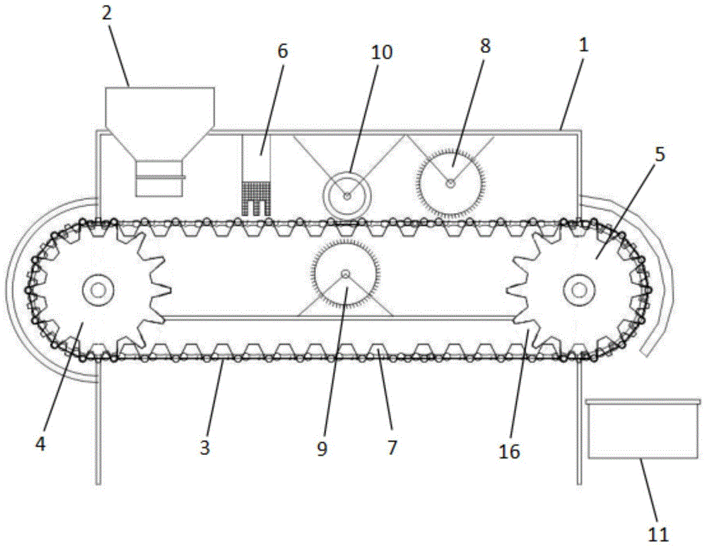
图1为本发明的壳尾去除装置内部结构示意图;Fig. 1 is a schematic diagram of the internal structure of the shell tail removal device of the present invention;
图2为本发明的加料箱内部结构示意图;Fig. 2 is a schematic diagram of the internal structure of the charging box of the present invention;
图3为本发明的传输带的结构示意图;Fig. 3 is the structural representation of the conveyor belt of the present invention;
图4为本发明的归置器倒置结构示意图;Fig. 4 is the schematic diagram of the inverted structure of the arranger of the present invention;
图5为本发明的螺蛳盛装切割示意图。Fig. 5 is a schematic diagram of cutting the snail dress of the present invention.
其中:1-安装箱、2-加料箱、3-传送带、4-主动轮、5-从动轮、6-归置器、7-贯通式置螺槽、8-上剪切轮、9-下剪切轮、10-压轮、11-收集框、12-正置螺蛳、13-上切割线、14-倒置螺蛳、15-下切割线、16-贯穿式横向切槽、20-固定架、21-锥形储料斗、22-落料通道、23-电动伸缩杆、24-连接杆、25-锥形板、26-缓冲网、27-往复丝杆、61-基座、62-指状柱。Among them: 1-installation box, 2-feeding box, 3-conveyor belt, 4-driving wheel, 5-driven wheel, 6-resetter, 7-through-type screw groove, 8-up shear wheel, 9-down Shearing wheel, 10-pressing wheel, 11-collecting frame, 12-upright snail, 13-upper cutting line, 14-inverted snail, 15-lower cutting line, 16-penetrating transverse groove, 20-fixing frame, 21-Conical storage hopper, 22-Blanking channel, 23-Electric telescopic rod, 24-Connecting rod, 25-Conical plate, 26-Buffer net, 27-Reciprocating screw rod, 61-Base, 62-Finger column.
具体实施方式Detailed ways
下面结合实施例,对本发明作进一步的描述,但不构成对本发明的任何限制,任何人在本发明权利要求范围所做的有限次的修改,仍在本发明的权利要求范围内。Below in conjunction with embodiment, the present invention is further described, but does not constitute any restriction to the present invention, anyone makes the limited number of amendments in the scope of claims of the present invention, still within the scope of claims of the present invention.
参阅图1-图5,本发明的一种螺蛳的壳尾去除装置,包括安装箱1、加料箱2、传送机、归置器6、剪切组件和收集框11。其中,加料箱2、传送机、归置器6和剪切组件均安装于安装箱1中,收集框11设置与传送机的输出端。Referring to Fig. 1-Fig. 5, a shell tail removal device for snails according to the present invention includes an installation box 1, a
加料箱2用于预存待去尾的螺蛳。加料箱2中设有一锥形储料斗21,锥形储料斗21的下方设有一与其相连通的落料通道22。锥形储料斗21中安装有间歇落料机构,以使预存的螺蛳以周期性的间断落料方式落入到落料通道22中。落料通道22中安装有往复落料机构,用于落下的螺蛳进行水平往复振动处理,以使螺蛳均匀地落下。落下的螺蛳最终从加料箱2底部的出料口掉落。
为实现间歇落料机构的周期性的间断落料功能,本实施例的间歇落料机构包括锥形板25、连接杆24和电动伸缩杆23。锥形板25活动插接在锥形储料斗21中,且锥形板25与锥形储料斗21的底部相匹配,以使锥形板25可将锥形储料斗21的底部完全封闭;连接杆24固定安装在锥形板25的顶部,加料箱2的顶部固定安装有一固定架20,电动伸缩杆23固定安装在固定架20中,且电动伸缩杆23的伸缩端与连接杆24远离锥形板25的一端固定连接。In order to realize the periodic intermittent blanking function of the intermittent blanking mechanism, the intermittent blanking mechanism of this embodiment includes a
通过电动伸缩杆23驱使锥形板25进行上下的往复移动。当锥形板25向上移动时,其与锥形储料斗21的接触位置将分离,以使锥形板25与锥形储料斗21之间具有一间隙,螺蛳通过该间隙即可掉落至落料通道22中。当锥形板25向下移动且与锥形储料斗21接触时,该间隙将闭合,螺蛳被阻挡在锥形储料斗21中。如此往复,即实现了周期性的间断落料功能。而锥形板25设置为锥形状,有利于对锥形储料斗21中螺蛳的搅动,可有效的防止锥形板25与锥形储料斗21相分离时螺蛳发生堵塞而不能落料的现象。The
为实现落料通道22中螺蛳的均匀落料,本实施例的往复落料机构包括缓冲网26、往复丝杆27和电机。缓冲网26的网目单边长度为螺蛳体宽的1.2-1.5倍,以便于螺蛳通过缓冲网26。缓冲网26滑动安装在落料通道22中,且缓冲网26在移动过程中,始终将落料通道22隔断。其具体的实施方式可以为,将落料通道22设置为方形,缓冲网26的两端均贯穿并延伸至落料通道22的外侧,缓冲网26的两侧均通过滑轨与落料通道22滑动连接。如此,即可确保在缓冲网26的滑动距离小于缓冲网26延伸至落料通道22外侧部分的长度时,缓冲网26始终能将落料通道22隔断。In order to realize uniform blanking of snails in the blanking
往复丝杆27转动安装在加料箱2的外壁上,加料箱2的一侧开设有通槽,往复丝杆27的滑块贯穿通槽且与缓冲网26固定连接,往复丝杆27的滑块移动方向与缓冲网26的滑动方向一致。电机固定安装在加料箱2的侧壁上,电机的输出轴与往复丝杆27固定连接。通过电机的驱动作用即可实现缓冲网26的往复移动,从而实现了螺蛳的均匀落料。而且当螺蛳掉落在缓冲网26上时,缓冲网26能对螺蛳进行缓冲,可有效的降低螺蛳的掉落速度,减少螺蛳的破损。The
传送机位于加料箱2的下方,其用于接收从加料箱2中掉落下来的螺蛳。传送机与市面上的传送机结构一致,主要由电机、主动轮4、从动轮5和传送带3组成。如图3所示,本实施例的传送机与传统的传送机所不同的在于,本实施例的传送带3上设置了多个排列组合的贯通式置螺槽7。且本实施例以传送机的传送方向为排列组合的贯通式置螺槽7的列。主动轮4和从动轮5均从传送带3的内环中贯穿,且主动轮4和从动轮5的周面上均设有与贯通式置螺槽7相匹配的贯穿式横向切槽16。Conveyor is positioned at the below of
传送机的输出端位于安装箱1的外侧,收集框11则设置于传送机输出端的下方,用于接收被去尾后的螺蛳。The output end of the conveyor is positioned at the outside of the installation box 1, and the
贯通式置螺槽7用于盛放一个螺蛳,其内腔呈锥状结构。具体的,以传送带3表面上的贯通式置螺槽7为例,贯通式置螺槽7的上下均无底,大口在上小口在下。当规格相同或接近的螺蛳落入到贯通式置螺槽7中之后螺蛳的尾部要么朝上,要么朝下,如图5中的正置螺蛳12为尾部朝下,倒置螺蛳14为尾部朝下。当螺蛳尾部朝下时,其尾部正好露出小口外,其切割位置如图5中的下切割线15所示;当尾部朝上时,其尾部要高于尾部朝下的螺蛳的头部,其切割位置如图5中的上切割线13所示,从而达到对贯通式置螺槽7中的螺蛳尾部去除的目的。此外,根据统计得出,螺蛳的锥顶角为52-60°,因此,设置贯通式置螺槽7的相对面夹角与之相同,以达到更好的盛装和去尾效果。The through-
螺蛳掉落在传送机表面之后,会有部分螺蛳不完全落入到贯通式置螺槽7,如螺蛳横置在贯通式置螺槽7开口上。为使这些未完全落入在贯通式置螺槽7中的螺蛳归置于贯通式置螺槽7中,本实施例通过归置器6实现。After the snail falls on the conveyor surface, some snails will not completely fall into the through-
如图4所示,归置器6包括基座61和若干指状柱62。基座61设置于剪切组件一侧的传送机上方,若干指状柱62固定设置在基座61的底部。每相邻两列贯通式置螺槽7之间均设有指状柱62。当螺蛳未完全落入贯通式置螺槽7中时,该螺蛳的两端将突出于贯通式置螺槽7上端开口的范围,其通过指状柱62时,将指状柱62将与其产生干涉,使其移动。由于贯通式置螺槽7之间间隙很窄,因此,移动的螺蛳将失去平衡,进而掉落在贯通式置螺槽7中,从而实现了螺蛳的归置。As shown in FIG. 4 , the
由于螺蛳壳较脆,为减少指状柱62对螺蛳阻挡过程中螺蛳壳出现破损的现象,本实施例的指状柱62采用弹性材料制成,如橡胶、PU皮等。Since the snail shell is relatively brittle, in order to reduce the phenomenon of damage to the snail shell during the blocking process of the snail by the finger-shaped
当螺蛳归置完毕后,即可被传送至剪切组件进行剪切。为实现对尾部朝向不同的螺蛳进行去尾,本实施例的剪切组件包括上剪切轮8、下剪切轮9和压轮10。上剪切轮8转动安装在安装箱1中,且位于传送带3表面的上方,上剪切轮8与传送机表面的间隙小于螺蛳尾部的突出高度。下剪切轮9转动安装在安装箱1中,且位于传送带3的上带体和下带体之间。下剪切轮9与位于上带体上的贯通式置螺槽7底部之间的间隙小于螺蛳尾部的突出高度。上剪切轮8、下剪切轮9通过减速电机进行驱动。压轮10转动设置在传送机表面的上方,压轮10的竖向位置与下剪切轮9的竖向位置一致,且压轮10与传送机之间的间隙小于贯通式置螺槽7中螺蛳凸出的最小高度。即压轮10可对尾部朝下的螺蛳进行压紧。After the snails are reset, they can be sent to the cutting component for cutting. In order to remove the tail of snails with different tail orientations, the shearing assembly of this embodiment includes an
在去尾时,螺蛳被传送至压轮10下方且被压轮10压紧的同时,下剪切轮9将螺蛳尾部朝下的螺蛳尾部剪除。当尾部朝上的螺蛳被传送至上剪切轮8下方时,通过上剪切轮8实现将其尾部剪除。由于上剪切轮8在剪除尾部朝上的螺蛳尾部时,螺蛳尾部与上剪切轮8之间的干涉会使得螺蛳获得一压力,使其牢牢被压在贯通式置螺槽7中,从而实现螺蛳尾部剪除。When the tail is removed, the snail is sent to the bottom of the
优选的,压轮10的表面附有由软质弹性材料制成的弹性层,如橡胶或TPE材料等。Preferably, the surface of the
以上所述的仅是本发明的优选实施方式,应当指出对于本领域的技术人员来说,在不脱离本发明结构的前提下,还可以作出若干变形和改进,这些都不会影响本发明实施的效果和专利的实用性。What is described above is only the preferred embodiment of the present invention, it should be pointed out that for those skilled in the art, under the premise of not departing from the structure of the present invention, some deformations and improvements can also be made, and these will not affect the implementation of the present invention effect and utility of the patent.
Claims (10)
Priority Applications (1)
| Application Number | Priority Date | Filing Date | Title |
|---|---|---|---|
| CN202211491792.8A CN115918711A (en) | 2022-11-25 | 2022-11-25 | A shell tail removal device for snails |
Applications Claiming Priority (1)
| Application Number | Priority Date | Filing Date | Title |
|---|---|---|---|
| CN202211491792.8A CN115918711A (en) | 2022-11-25 | 2022-11-25 | A shell tail removal device for snails |
Publications (1)
| Publication Number | Publication Date |
|---|---|
| CN115918711A true CN115918711A (en) | 2023-04-07 |
Family
ID=86697047
Family Applications (1)
| Application Number | Title | Priority Date | Filing Date |
|---|---|---|---|
| CN202211491792.8A Pending CN115918711A (en) | 2022-11-25 | 2022-11-25 | A shell tail removal device for snails |
Country Status (1)
| Country | Link |
|---|---|
| CN (1) | CN115918711A (en) |
Cited By (1)
| Publication number | Priority date | Publication date | Assignee | Title |
|---|---|---|---|---|
| CN117717111A (en) * | 2024-01-19 | 2024-03-19 | 安徽金国源中药股份有限公司 | A kind of cleaning equipment |
Citations (9)
| Publication number | Priority date | Publication date | Assignee | Title |
|---|---|---|---|---|
| JPH07135949A (en) * | 1993-11-19 | 1995-05-30 | Kubota Corp | Harvested vegetable processing equipment |
| CA2743351A1 (en) * | 2008-11-11 | 2010-05-20 | Albus Solutions Limited | Apparatus for processing crustaceans |
| CN102349563A (en) * | 2011-10-02 | 2012-02-15 | 冯婷婷 | Snail tail removing machine |
| CN105123884A (en) * | 2015-10-01 | 2015-12-09 | 卢乐 | Full-automatic snail tail cutting machine |
| CN107185445A (en) * | 2017-08-01 | 2017-09-22 | 朱碧潞 | A kind of feed manufacturing shaker mixer |
| CN108208121A (en) * | 2017-12-26 | 2018-06-29 | 南京典卡木软件有限公司 | The Intelligent Machining processing unit and method of a kind of spiral shell |
| CN108739962A (en) * | 2018-06-08 | 2018-11-06 | 临沂市科学技术合作与应用研究院 | A kind of cone conch truncates processing machine |
| CN215100325U (en) * | 2021-07-22 | 2021-12-10 | 广东三宝新材料科技股份有限公司 | Automatic powder device of beating of synthetic mica |
| CN215873404U (en) * | 2021-02-07 | 2022-02-22 | 王振 | Inverted garlic rhizome cutting device and cutting machine |
-
2022
- 2022-11-25 CN CN202211491792.8A patent/CN115918711A/en active Pending
Patent Citations (9)
| Publication number | Priority date | Publication date | Assignee | Title |
|---|---|---|---|---|
| JPH07135949A (en) * | 1993-11-19 | 1995-05-30 | Kubota Corp | Harvested vegetable processing equipment |
| CA2743351A1 (en) * | 2008-11-11 | 2010-05-20 | Albus Solutions Limited | Apparatus for processing crustaceans |
| CN102349563A (en) * | 2011-10-02 | 2012-02-15 | 冯婷婷 | Snail tail removing machine |
| CN105123884A (en) * | 2015-10-01 | 2015-12-09 | 卢乐 | Full-automatic snail tail cutting machine |
| CN107185445A (en) * | 2017-08-01 | 2017-09-22 | 朱碧潞 | A kind of feed manufacturing shaker mixer |
| CN108208121A (en) * | 2017-12-26 | 2018-06-29 | 南京典卡木软件有限公司 | The Intelligent Machining processing unit and method of a kind of spiral shell |
| CN108739962A (en) * | 2018-06-08 | 2018-11-06 | 临沂市科学技术合作与应用研究院 | A kind of cone conch truncates processing machine |
| CN215873404U (en) * | 2021-02-07 | 2022-02-22 | 王振 | Inverted garlic rhizome cutting device and cutting machine |
| CN215100325U (en) * | 2021-07-22 | 2021-12-10 | 广东三宝新材料科技股份有限公司 | Automatic powder device of beating of synthetic mica |
Non-Patent Citations (1)
| Title |
|---|
| 张振文等: "带式输送机工程设计与应用", vol. 1, 31 January 2015, 冶金工业出版社, pages: 330 * |
Cited By (2)
| Publication number | Priority date | Publication date | Assignee | Title |
|---|---|---|---|---|
| CN117717111A (en) * | 2024-01-19 | 2024-03-19 | 安徽金国源中药股份有限公司 | A kind of cleaning equipment |
| CN117717111B (en) * | 2024-01-19 | 2025-08-19 | 安徽金国源中药股份有限公司 | Oyster cleaning equipment |
Similar Documents
| Publication | Publication Date | Title |
|---|---|---|
| CN105725224B (en) | Walnut shell breaking device and using method thereof | |
| CN209089961U (en) | One seed pod pears process quick draining device | |
| CN113679055A (en) | Fresh litchi stoner | |
| CN110538812A (en) | Color separation device is used in gold date processing | |
| CN206314537U (en) | Walnut shell breaking device with positioning conveying function | |
| CN214021822U (en) | Screening and cutting integration sesame oil processing equipment | |
| CN219004471U (en) | Foundry waste sand screening machine | |
| CN106945094B (en) | A kind of betel nut fish gutting machine being continuously driven | |
| CN106367197A (en) | Oil expression production line of camellia oil | |
| CN213939653U (en) | A breaking apparatus for nut production | |
| CN105996065B (en) | A kind of multi-station intermittent punching type walnut shell-breaking device | |
| CN211672335U (en) | Oil tea fruit peeling device | |
| CN106881742A (en) | A kind of continuous filament cutter of fresh bamboo shoot and method | |
| CN203040637U (en) | Automatic sorting system of husks and cores of green and red peppers | |
| CN218835133U (en) | Granule screening machine with uniformly spread filter screen | |
| CN207040734U (en) | A kind of tealeaves stem cutting machine | |
| CN108741173A (en) | A kind of green soy bean is peeled off production line automatically | |
| CN210695851U (en) | Industrialized litchi peeling device | |
| CN209073507U (en) | A kind of Feed Manufacturing feeding device | |
| CN209188879U (en) | A kind of cape jasmine fruit efficient pulverizing device | |
| CN120898874B (en) | Energy-saving fish meat quick separation equipment | |
| CN206653438U (en) | A kind of continuous filament cutter of fresh bamboo shoot | |
| CN208164378U (en) | A kind of feeding impurity removing equipment for charcoal production | |
| CN206851900U (en) | A kind of automatic grouting machine | |
| CN220458475U (en) | Sorting device for seafood processing |
Legal Events
| Date | Code | Title | Description |
|---|---|---|---|
| PB01 | Publication | ||
| PB01 | Publication | ||
| SE01 | Entry into force of request for substantive examination | ||
| SE01 | Entry into force of request for substantive examination | ||
| RJ01 | Rejection of invention patent application after publication |
Application publication date: 20230407 |