CN115910662A - A switch cabinet interlock protection mechanism and switch cabinet - Google Patents
A switch cabinet interlock protection mechanism and switch cabinet Download PDFInfo
- Publication number
- CN115910662A CN115910662A CN202211518957.6A CN202211518957A CN115910662A CN 115910662 A CN115910662 A CN 115910662A CN 202211518957 A CN202211518957 A CN 202211518957A CN 115910662 A CN115910662 A CN 115910662A
- Authority
- CN
- China
- Prior art keywords
- rotating shaft
- shaft body
- accommodating groove
- switch
- handle
- Prior art date
- Legal status (The legal status is an assumption and is not a legal conclusion. Google has not performed a legal analysis and makes no representation as to the accuracy of the status listed.)
- Granted
Links
Images


Classifications
-
- Y—GENERAL TAGGING OF NEW TECHNOLOGICAL DEVELOPMENTS; GENERAL TAGGING OF CROSS-SECTIONAL TECHNOLOGIES SPANNING OVER SEVERAL SECTIONS OF THE IPC; TECHNICAL SUBJECTS COVERED BY FORMER USPC CROSS-REFERENCE ART COLLECTIONS [XRACs] AND DIGESTS
- Y02—TECHNOLOGIES OR APPLICATIONS FOR MITIGATION OR ADAPTATION AGAINST CLIMATE CHANGE
- Y02T—CLIMATE CHANGE MITIGATION TECHNOLOGIES RELATED TO TRANSPORTATION
- Y02T10/00—Road transport of goods or passengers
- Y02T10/60—Other road transportation technologies with climate change mitigation effect
- Y02T10/70—Energy storage systems for electromobility, e.g. batteries
-
- Y—GENERAL TAGGING OF NEW TECHNOLOGICAL DEVELOPMENTS; GENERAL TAGGING OF CROSS-SECTIONAL TECHNOLOGIES SPANNING OVER SEVERAL SECTIONS OF THE IPC; TECHNICAL SUBJECTS COVERED BY FORMER USPC CROSS-REFERENCE ART COLLECTIONS [XRACs] AND DIGESTS
- Y02—TECHNOLOGIES OR APPLICATIONS FOR MITIGATION OR ADAPTATION AGAINST CLIMATE CHANGE
- Y02T—CLIMATE CHANGE MITIGATION TECHNOLOGIES RELATED TO TRANSPORTATION
- Y02T10/00—Road transport of goods or passengers
- Y02T10/60—Other road transportation technologies with climate change mitigation effect
- Y02T10/7072—Electromobility specific charging systems or methods for batteries, ultracapacitors, supercapacitors or double-layer capacitors
Landscapes
- Patch Boards (AREA)
Abstract
本发明公开了一种开关柜联锁保护机构及开关柜,涉及电气设备的技术领域,包括:外保护壳,穿设安装在柜门上;隔离开关控制机构,包括绳索,驱动机构;驱动机构穿插安装在外保护壳内;驱动机构包括安装块、转动轴体、限位件;转动轴体上设有卡齿;安装块内设有三个容置槽,外力转动或者平移转动轴体,能够使转动轴体的卡齿切换进不同的容置槽内,且在限位件的作用下,使卡齿位于其中一容置槽内,通过切换卡齿位置,从而拉动绳索完成隔离开关的分闸和合闸,结构简单巧妙,能够使操作人员在开门前实现分闸断电,安全性高;在转动轴体上设有手柄盘,手柄盘上的插孔与卡齿的位置一致,便于操作人员直观的观察出卡齿的位置,从而判断隔离开关的状态。
The invention discloses a switchgear interlocking protection mechanism and a switchgear, relating to the technical field of electrical equipment, comprising: an outer protective shell, which is installed on the cabinet door; an isolating switch control mechanism, including a rope, a driving mechanism; a driving mechanism It is interspersed and installed in the outer protective shell; the driving mechanism includes a mounting block, a rotating shaft body, and a limit piece; the rotating shaft body is provided with locking teeth; there are three accommodating slots in the mounting block, and the external force rotates or translates the rotating shaft body, which can make the The locking teeth of the rotating shaft are switched into different accommodation slots, and under the action of the limiter, the locking teeth are located in one of the accommodation slots, and the opening of the disconnector is completed by pulling the rope by switching the position of the locking teeth. And closing, the structure is simple and ingenious, which can enable the operator to open the gate and cut off the power before opening the door, with high safety; there is a handle plate on the rotating shaft, and the jack on the handle plate is consistent with the position of the locking tooth, which is convenient for the operator Visually observe the position of the locking teeth, so as to judge the state of the isolating switch.
Description
技术领域technical field
本发明涉及电气设备的技术领域,尤其涉及一种开关柜联锁保护机构及开关柜。The invention relates to the technical field of electrical equipment, in particular to a switch cabinet interlock protection mechanism and a switch cabinet.
背景技术Background technique
开关柜是一种电气设备,开关柜的主要作用是在电力系统进行发电、输电、配电和电能转换的过程中,进行开合、控制和保护用电设备。开关柜内的部件主要有断路器、隔离开关、负荷开关、操作机构、互感器以及各种保护装置等组成。The switchgear is a kind of electrical equipment. The main function of the switchgear is to open and close, control and protect the electrical equipment during the process of power generation, transmission, distribution and power conversion in the power system. The components in the switch cabinet are mainly composed of circuit breakers, disconnectors, load switches, operating mechanisms, transformers and various protection devices.
在实际操作中,需要对开关柜内部进行分闸断电,操作人员才能开启开关柜柜门以保证安全,但在实际操作中会存在忘记关闭电磁开关的可能,现在的联锁机构不能使操作人员直观观察联锁机构的操作状态,导致在联锁机构发生故障未工作时不易察觉。In actual operation, it is necessary to open and cut off the power inside the switch cabinet, so that the operator can open the door of the switch cabinet to ensure safety. However, in actual operation, there may be a possibility of forgetting to close the electromagnetic switch. Personnel visually observe the operating state of the interlock mechanism, which makes it difficult to detect when the interlock mechanism breaks down and does not work.
申请号为CN112701604B的中国专利公开了一种开关柜保护联锁机构,以及使用该联锁机构的金属铠装移开式开关柜,属于电气设备领域,联锁机构包括设置在开关柜门上或者门框上的若干凹槽,和设置在凹槽内相互配合的固定组件、滑动组件和限位组件,同时固定组件和滑动组件再通过绳缆联动连接到隔离开关。上述专利中滑动板裸露在开关柜外侧,容易出现非需要误操作的情况,影响开关柜的使用以及存在一定的安全风险。The Chinese patent with the application number CN112701604B discloses a switchgear protection interlocking mechanism and a metal armored removable switchgear using the interlocking mechanism, which belongs to the field of electrical equipment. The interlocking mechanism includes being arranged on the switchgear door or A plurality of grooves on the door frame, and a fixed component, a sliding component and a limit component arranged in the grooves to cooperate with each other, and the fixed component and the sliding component are connected to the isolation switch through a rope linkage. In the above patent, the sliding plate is exposed on the outside of the switch cabinet, which is prone to unnecessary misoperation, affects the use of the switch cabinet and poses certain safety risks.
发明内容Contents of the invention
本发明要解决的主要技术问题是:提供一种开关柜联锁保护机构及开关柜,能够解决上述背景技术提到的问题。The main technical problem to be solved by the present invention is to provide a switch cabinet interlocking protection mechanism and a switch cabinet, which can solve the problems mentioned in the above-mentioned background technology.
为了解决上述的主要技术问题采取以下技术方案实现:In order to solve the above-mentioned main technical problems, the following technical solutions are adopted to realize:
一种开关柜联锁保护机构,包括:A switch cabinet interlock protection mechanism, comprising:
外保护壳,穿设安装在柜门上,且两端开口;在所述外保护壳内设有阶梯面;The outer protective shell is installed on the cabinet door and has openings at both ends; a stepped surface is provided inside the outer protective shell;
隔离开关控制机构,包括与隔离开关手柄相连的绳索,控制绳索拉动以使隔离开关分闸或者合闸的驱动机构;所述隔离开关手柄安装在开关柜操作室内;所述驱动机构穿插安装在外保护壳内;The isolating switch control mechanism includes a rope connected to the isolating switch handle, and a driving mechanism that controls the pulling of the rope to make the isolating switch open or close; the isolating switch handle is installed in the switch cabinet operating room; the driving mechanism is inserted and installed outside for protection inside the shell;
其中,所述驱动机构包括安装块、转动轴体、限位件;所述安装块安装在外保护壳内;所述转动轴体位于柜门内侧的端部连接有与绳索相连的连接杆;所述转动轴体安装在安装块内;所述转动轴体上还设有卡齿;所述安装块内设有三个容置槽;所述限位件用于将卡齿限位在其中一容置槽内且安装在转动轴体的端部;当所述转动轴体在安装块内自转或平移时,所述卡齿能够切换进入三个容置槽内,以便连接杆移动后拉动隔离开关手柄。Wherein, the driving mechanism includes a mounting block, a rotating shaft body, and a limiter; the mounting block is installed in the outer protective shell; the end of the rotating shaft body located inside the cabinet door is connected with a connecting rod connected with a rope; The rotating shaft body is installed in the mounting block; the rotating shaft body is also provided with locking teeth; the mounting block is provided with three accommodating grooves; the limiting member is used to limit the locking teeth in one of them placed in the groove and installed at the end of the rotating shaft; when the rotating shaft rotates or translates in the mounting block, the locking teeth can be switched into the three accommodating grooves so that the connecting rod moves and pulls the isolation switch handle.
优选地,所述安装块包括左右固定在一起的安装板和固定块;所述固定块靠近隔离开关手柄;所述容置槽位于固定块内;所述转动轴体穿设连接在安装板上;所述固定块上开设有容置转动轴体的通槽;所述通槽与三个容置槽相通。Preferably, the mounting block includes a mounting plate and a fixing block fixed together left and right; the fixing block is close to the handle of the isolation switch; the accommodating groove is located in the fixing block; the rotating shaft is passed through and connected to the mounting plate ; The fixed block is provided with a through groove for accommodating the rotating shaft body; the through groove communicates with the three accommodating grooves.
优选地,所述容置槽一和容置槽二分别位于通槽的相对两侧,且容置槽一靠近隔离开关手柄;所述容置槽一和容置槽二均沿转动轴体的轴向贯穿固定块;所述容置槽三沿转动轴体的径向分布在固定块内,且容置槽三的起点与容置槽二相通,终点靠近容置槽一;当所述卡齿自容置槽一进入容置槽二时,所述连接杆移动,拉动隔离开关手柄分闸;当所述卡齿自容置槽三进入容置槽二时,所述连接杆移动,拉动隔离开关手柄合闸。Preferably, the accommodating groove one and the accommodating groove two are respectively located on opposite sides of the through groove, and the accommodating groove one is close to the handle of the isolation switch; Axially runs through the fixed block; the three accommodation grooves are distributed in the fixed block along the radial direction of the rotating shaft body, and the starting point of the three accommodation grooves communicates with the second accommodation groove, and the end point is close to the first accommodation groove; when the card When the tooth enters the second accommodation slot from the first accommodation slot, the connecting rod moves and pulls the handle of the isolating switch to open the gate; when the locking tooth enters the second accommodation slot from the third accommodation slot, the connecting rod moves and pulls The isolating switch handle is closed.
优选地,所述限位件包括限位弹簧和扭簧;所述限位弹簧套设在转动轴体背离隔离开关手柄的一侧,且固定在安装板上;所述扭簧的一端安装在固定块,另一端安装在转动轴体靠近连接杆的端部;在所述限位弹簧和扭簧的弹力作用下,所述卡齿位于容置槽一内的中间位置;按压并转动所述转动轴体时,所述卡齿能够进入容置槽二内,并在所述限位弹簧复位后到达容置槽二的中间位置;当所述卡齿位于容置槽二的中间位置时,所述扭簧能够驱使卡齿转动至容置槽三的终点位置。Preferably, the limiting member includes a limiting spring and a torsion spring; the limiting spring is sleeved on the side of the rotating shaft away from the handle of the isolation switch, and fixed on the mounting plate; one end of the torsion spring is installed on The other end of the fixed block is installed on the end of the rotating shaft close to the connecting rod; under the elastic force of the limit spring and the torsion spring, the locking teeth are located in the middle of the accommodating groove one; press and rotate the When the shaft body is rotated, the locking teeth can enter the second accommodation groove, and reach the middle position of the second accommodation groove after the limit spring is reset; when the locking teeth are located at the middle position of the second accommodation groove, The torsion spring can drive the locking teeth to rotate to the end position of the accommodation groove three.
进一步地,所述阶梯面设有用于开合柜门的锁体孔;在所述转动轴体背离隔离开关手柄的端部设有手柄盘;所述手柄盘上有插孔;所述插孔与卡齿的连接线与转动轴体的轴线平行;当所述卡齿位于容置槽三内时,所述插孔正对锁体孔。Further, the step surface is provided with a lock body hole for opening and closing the cabinet door; a handle plate is provided at the end of the rotating shaft away from the handle of the isolating switch; there is a jack on the handle plate; the jack The connection line with the locking teeth is parallel to the axis of the rotating shaft; when the locking teeth are located in the accommodation groove three, the insertion hole is facing the hole of the lock body.
进一步地,在所述外保护壳的位于柜门外侧端部可拆卸连接有盖子。Further, a cover is detachably connected to the outer end of the outer protective shell located outside the cabinet door.
进一步地,所述绳索上设有缓冲弹簧;所述连接杆上设有与绳索相连的万向连接环;所述开关柜的柜体内设有限位绳索移动方向的滚轮组件。Further, the rope is provided with a buffer spring; the connecting rod is provided with a universal connecting ring connected with the rope; the cabinet of the switch cabinet is provided with a roller assembly that limits the moving direction of the rope.
优选地,所述滚轮组件包括第一方向滚轮和与第一方向滚轮轴线垂直的第二方向滚轮。Preferably, the roller assembly includes a first direction roller and a second direction roller perpendicular to the axis of the first direction roller.
一种开关柜,包含上述的联锁保护机构。A switch cabinet includes the above-mentioned interlocking protection mechanism.
与现有技术相比,本发明应用于开关柜中具备下列优点:Compared with the prior art, the present invention has the following advantages when applied to switch cabinets:
(1)隔离开关控制机构包括绳索和驱动机构,驱动机构包括转动轴体、安装块和限位件;所述安装块内设有三个容置槽,外力转动或者平移转动轴体,能够使转动轴体的卡齿切换进不同的容置槽内,且在限位件的作用下,使卡齿位于其中一容置槽内,通过切换卡齿位置,从而拉动绳索完成隔离开关的分闸和合闸,结构简单巧妙,能够使操作人员在开门前实现分闸断电,安全性高。(1) The isolation switch control mechanism includes a rope and a driving mechanism, and the driving mechanism includes a rotating shaft body, a mounting block and a limit piece; the mounting block is provided with three accommodation grooves, and the external force rotates or translates the rotating shaft body to make the rotation The locking teeth of the shaft body are switched into different accommodation slots, and under the action of the limiter, the locking teeth are located in one of the accommodation slots. By switching the locking teeth position, the rope is pulled to complete the opening and closing of the isolating switch. The gate has a simple and ingenious structure, which enables the operator to open the gate and cut off the power before opening the door, with high safety.
(2)在转动轴体上设有手柄盘,手柄盘上的插孔与卡齿的位置一致,从而便于操作人员直观的观察出卡齿的位置,从而判断出隔离开关的状态。(2) A handle plate is provided on the rotating shaft body, and the jack on the handle plate is consistent with the position of the locking teeth, so that the operator can intuitively observe the position of the locking teeth, thereby judging the state of the isolating switch.
(3)当卡齿位于容置槽三时,即隔离开关处于分闸断电状态时,插孔与位于外保护壳内的锁体孔才能正对,此时操作人员才能打开柜门,进一步提高了安全性。(3) When the locking teeth are located in the accommodation slot three, that is, when the isolating switch is in the off state, the jack and the lock body hole located in the outer protective shell can be facing each other. At this time, the operator can open the cabinet door, further Improved security.
附图说明Description of drawings
为了更清楚地说明本发明实施方式的技术方案,下面将对实施方式中所需要使用的附图做简要介绍,显而易见地,下面描述中的附图仅仅是本发明的一些实施例,对于本领域普通技术人员来讲,在不付出创造性劳动的前提下,还可以根据这些附图获得其他的附图。In order to more clearly illustrate the technical solutions of the embodiments of the present invention, the following will briefly introduce the accompanying drawings that need to be used in the embodiments. Obviously, the accompanying drawings in the following description are only some embodiments of the present invention. For those skilled in the art Ordinary technicians can also obtain other drawings based on these drawings on the premise of not paying creative work.
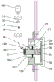
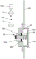
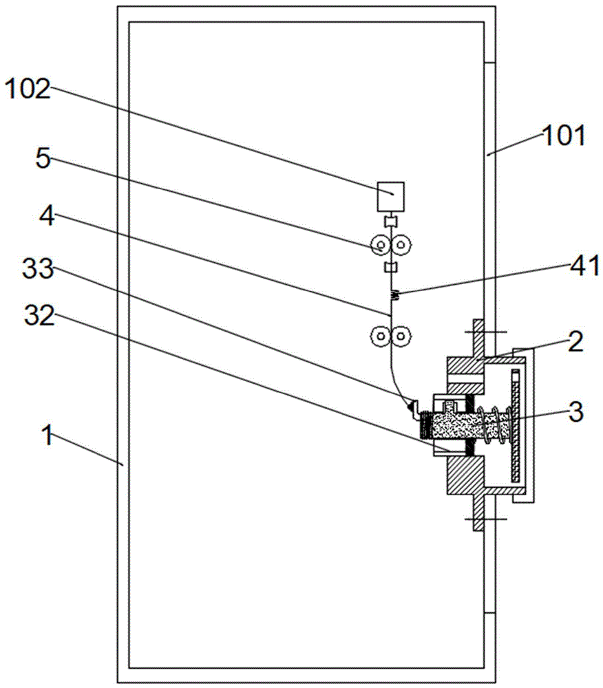
图1为当隔离开关处于合闸状态的整体结构示意图;Figure 1 is a schematic diagram of the overall structure when the isolating switch is in the closing state;
图2为当卡齿位于容置槽一内时驱动机构的放大结构示意图;Fig. 2 is a schematic diagram showing an enlarged structure of the driving mechanism when the locking teeth are located in the
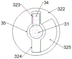
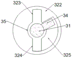
图3为当卡齿位于容置槽一内时固定块的纵截面结构示意图;Fig. 3 is a schematic diagram of the longitudinal section structure of the fixed block when the locking teeth are located in the
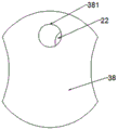
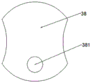
图4为当卡齿位于容置槽一内时手柄盘的左视结构示意图;Fig. 4 is a left view structural diagram of the handle plate when the locking teeth are located in the first accommodation slot;
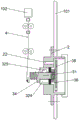
图5为当卡齿位于容置槽二内时驱动机构的放大结构示意图;Fig. 5 is a schematic diagram of the enlarged structure of the driving mechanism when the locking teeth are located in the second accommodation slot;
图6为当卡齿位于容置槽二内时固定块的纵截面结构示意图;Fig. 6 is a schematic diagram of the longitudinal section structure of the fixed block when the locking teeth are located in the second accommodation groove;
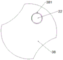
图7为当卡齿位于容置槽二内时手柄盘的左视结构示意图;Fig. 7 is a schematic diagram of the left view structure of the handle plate when the locking teeth are located in the second accommodating groove;
图8为当卡齿位于容置槽三内时驱动机构的放大结构示意图;Fig. 8 is an enlarged structural schematic diagram of the driving mechanism when the locking teeth are located in the accommodation groove three;
图9为当卡齿位于容置槽三内时固定块的纵截面结构示意图;Fig. 9 is a schematic diagram of the longitudinal section structure of the fixed block when the locking teeth are located in the accommodation groove three;
图10为当卡齿位于容置槽三内时手柄盘的左视结构示意图。Fig. 10 is a left view structural diagram of the handle plate when the locking teeth are located in the accommodation groove three.
图中:1为柜体,101为柜门,102为隔离开关手柄,2为外保护壳,21为阶梯面,22为锁体孔,23为盖子,3为驱动机构,31为转动轴体,32为安装块,321为安装板,322为固定块,323为容置槽一,324为容置槽二,325为容置槽三,33为连接杆,331为万向连接环,34为卡齿,35为通槽,36为限位弹簧,37为扭簧,38为手柄盘,381为插孔,4为绳索,41为缓冲弹簧,5为滚轮组件,51为第一方向滚轮,52为第二方向滚轮。In the figure: 1 is the cabinet body, 101 is the cabinet door, 102 is the isolating switch handle, 2 is the outer protective shell, 21 is the step surface, 22 is the lock body hole, 23 is the cover, 3 is the driving mechanism, 31 is the rotating shaft , 32 is a mounting block, 321 is a mounting plate, 322 is a fixed block, 323 is accommodating groove one, 324 is accommodating groove two, 325 is accommodating groove three, 33 is a connecting rod, 331 is a universal connecting ring, 34 35 is a slot, 36 is a limit spring, 37 is a torsion spring, 38 is a handle plate, 381 is a socket, 4 is a rope, 41 is a buffer spring, 5 is a roller assembly, 51 is a first direction roller , 52 is the second direction roller.
具体实施方式Detailed ways
下面将结合本发明实施例中的附图,对本发明实施例中的技术方案进行清楚、完整地描述,显然,所描述的实施例仅仅是本发明一部分实施例,而不是全部实施例。基于本发明中的实施例,本领域普通技术人员在没有做出创造性劳动前提下所获得的所有其他实施例,都属于本发明保护的范围。另外,文中所提到的所有连接关系,并非单指构件直接相接,而是指可根据具体实施情况,通过添加或减少联接辅件,来组成更优的联接结构。The following will clearly and completely describe the technical solutions in the embodiments of the present invention in conjunction with the accompanying drawings in the embodiments of the present invention. Obviously, the described embodiments are only some of the embodiments of the present invention, not all of them. Based on the embodiments of the present invention, all other embodiments obtained by persons of ordinary skill in the art without making creative efforts belong to the protection scope of the present invention. In addition, all the connection relationships mentioned in this article do not refer to the direct connection of components, but mean that a better connection structure can be formed by adding or reducing connection accessories according to the specific implementation situation.
实施例一、Embodiment one,
请参阅图1-10所示,一种开关柜联锁保护机构,包括外保护壳2和隔离开关控制机构;所述外保护壳2用于安装隔离开关控制机构和保护隔离开关控制机构。Please refer to Fig. 1-10, a switch cabinet interlocking protection mechanism includes an outer
隔离开关安装在柜体1内的操作室内,通过拉动隔离开关手柄102实现隔离开关分闸断电或者合闸通电。The isolating switch is installed in the operating room of the
外保护壳2,横向穿设的安装在开关柜柜体1的柜门101上,优选的外保护壳2通过螺钉可拆卸的安装在柜门101上,便于更换;所述外保护壳2的两端开口,内部设有阶梯面21;外保护壳2的小头端位于柜门101内侧;所述外保护壳2的位于柜门101外侧端部可拆卸连接有盖子23,即盖子23铰接在外保护壳2上,或者螺纹连接在外保护壳2上。The outer
隔离开关控制机构包括绳索4和驱动机构3;所述绳索4与隔离开关的手柄相连;所述驱动机构3能够拉动绳索4实现隔离开关分闸和合闸,具体的绳索4的一端连接隔离开关的手柄,另一端连接在驱动机构3上;所述驱动机构3穿插安装在外保护壳2内。The isolating switch control mechanism includes a
驱动机构3包括安装块32、转动轴体31、限位件;所述安装块32包括安装板321和固定块322;所述安装板321和固定块322沿转动轴体31的轴向分布;所述安装板321安装在固定块322上;所述固定块322相对安装板321靠近隔离开关手柄102;所述安装板321和固定块322均位于外壳体内;所述固定块322内设有通槽35,所述转动轴体31能够在通槽35内转动或者来回滑动;所述转动轴体31连接在安装板321上,即转动轴体31能够在安装板321上转动和滑动,具体的安装方式可以参考现有技术。The
固定块322上设有三个容置槽,所述转动轴体31上设有沿着转动轴体31径向延伸的卡齿34;所述卡齿34能够切换进入三个容置槽中的任意一个;卡齿34的切换依赖转动轴体31的平移和自转;在所述转动轴体31位于柜门101内侧的端部连接有连接杆33;所述连接杆33上安装有万向连接环331;所述绳索4连接在万向连接环331上,在转动轴体31自转时,连接杆33也发生转动;所述连接杆33的延伸方向是朝向转动轴体31的径向,在转动轴体31自转时,绳索4的位置发生变化,从而拉动隔离开关手柄102。The
三个所述容置槽均与通槽35相通;所述容置槽一323和容置槽二324均沿转动轴体31的轴向延伸,且贯穿固定块322;所述容置槽一323和容置槽二324分别位于通槽35的相对两侧,容置槽一323靠近隔离开关手柄102,所述容置槽三325沿转动轴体31的径向分布在固定块322内,容置槽三325的起点与容置槽二324相通,终点靠近容置槽一323,即容置槽三325在转动轴体31的径向方向上的投影为扇环形状,扇环的小径为通槽35的外径。The three accommodating grooves all communicate with the through
限位件用于将卡齿34限位在其中一容置槽内且安装在转动轴体31的端部;所述限位件包括限位弹簧36和扭簧37;所述限位弹簧36套设在转动轴体31背离隔离开关的一侧,且固定在安装板321上;所述扭簧37的一端安装在固定块322,另一端安装在转动轴体31靠近连接杆33的端部;在所述限位弹簧36和扭簧37的初始状态下,卡齿34位于容置槽一323内的中间位置,中间位置指的是容置槽一323在转动轴体31轴向位置的中间;按压并转动所述转动轴体31时,所述卡齿34能够进入容置槽二324内,此时限位弹簧36和扭簧37均发生形变,松开按压后,卡齿34移动至容置槽二324内的中间位置,当卡齿34移动至容置槽二324内的中间位置时,限位弹簧36恢复初始状态,扭簧37仍处于扭转状态,在扭簧37的作用下,卡齿34从容置槽二324中移动至容置槽三325的终点位置,此时扭簧37未完全恢复初始状态,因此能够限位卡齿34抵在容置槽三325的终点位置;卡齿34从容置槽一323移动到容置槽三325内,连接杆33位置发生移动,绳索4受到一次拉动后回位,从而拉动隔离开关手柄102,实现分闸断电;当需要合闸时,向容置槽二324的方向转动转动轴体31,卡齿34从容置槽三325进入容置槽二324,然后按压旋转转动轴体31,使卡齿34脱离容置槽二324并移动至容置槽一323的一侧,此时在限位弹簧36的复位作用下,卡齿34回位至容置槽一323,即卡齿34从容置槽三325进入容置槽二324,再进入容置槽一323后,隔离开关手柄102第二次受到拉动并回位,从而完成合闸通电。The limiting member is used to limit the locking
在所述转动轴体31背离隔离开关手柄102的端部设有手柄盘38;所述手柄盘38上有插孔381;所述插孔381与卡齿34的连接线与转动轴体31的轴线平行;通过观察插孔381的位置能够知晓卡齿34的位置,从而便于完成分闸和合闸。A
实施例二、Embodiment two,
请参阅图1-10,实施例二与实施例一之间的区别在于在保留实施例一的基础上,所述阶梯面21设有用于开合柜门101的锁体孔22;当所述卡齿34位于容置槽三325时,此时隔离开关处于分闸断电状态,所述插孔381正对锁体孔22,操作人员才能打开柜门101,提高安全性。Please refer to Figures 1-10, the difference between the second embodiment and the first embodiment is that on the basis of retaining the first embodiment, the
本发明的工作过程为:使用时,打开位于外保护壳2外侧的盖子23,使手柄盘38裸露出来,按压手柄盘38后转动手柄盘38,此时卡齿34脱离容置槽一323,并随着转动正对容置槽二324,缓慢松开手柄盘38,在限位弹簧36的作用下,卡齿34位于容置槽二324的中间位置,完全松开手柄盘38,在扭簧37的作用下,卡齿34进入容置槽三325的终点位置,此时完成对隔离开关手柄102的一次拉动,实现隔离开关手柄102的分闸断电;从手柄盘38的插孔381中插入钥匙,钥匙插入锁体孔22内,从而打开柜门101;当需要关闭柜门101时,先锁紧锁体孔22,并反向操作手柄盘38即可实现合闸通电。The working process of the present invention is as follows: when in use, open the
实施例三、Embodiment three,
请参阅图1-10,实施例三与实施例二之间的区别在于在保留实施例二的基础上,所述绳索4上设有缓冲弹簧41;缓冲弹簧41能够使卡齿34位于容置槽三325时,连接杆33对绳索4的拉力一与卡齿34位于容置槽一323时,连接杆33对绳索4的拉力二保持一致;所述柜体1内设有限位绳索4移动方向的滚轮组件5,所述滚轮组件5包括第一方向滚轮51和与第一方向滚轮51轴线垂直的第二方向滚轮52;在靠近隔离开关的位置设置有滚轮组件5,滚轮组件5能够保证隔离开关的正常分闸和合闸,滚轮组件5的结构可以参考现有技术。Please refer to Fig. 1-10, the difference between the third embodiment and the second embodiment is that on the basis of retaining the second embodiment, the said
实施例四、Embodiment four,
请参阅图1-10所示,一种开关柜,包含上述联锁保护机构。Please refer to Fig. 1-10, which shows a switchgear including the above-mentioned interlocking protection mechanism.
需要说明的是,本发明中的“上、下、左、右、内、外”是以图中零部件的相对位置为基准定义的,只是为了描述技术方案的清楚及方便,应当理解,此方位词的应用对本申请的保护范围不构成限制。It should be noted that "up, down, left, right, inside, and outside" in the present invention are defined based on the relative positions of the components in the figure, and are only for the clarity and convenience of describing the technical solution. It should be understood that the The application of orientation words does not limit the protection scope of this application.
以上所述的实施方式均为优选实施方式而已,并不用于限制本发明,尽管参照前述实施例对本发明进行了详细的说明,对于本领域的技术人员来说,依然可以对前述实施所记载的技术方案进行修改,或者对其中部分技术特性进行等同替换,凡在本发明精神和原则之内,所作的任何修改、等同替换、改进等,均应包含在本发明的保护范围内。The above-mentioned implementations are all preferred implementations, and are not intended to limit the present invention. Although the present invention has been described in detail with reference to the foregoing examples, those skilled in the art can still describe the foregoing implementations. Any modification, equivalent replacement, improvement, etc. made within the spirit and principles of the present invention shall be included in the protection scope of the present invention.
Claims (9)
Priority Applications (1)
| Application Number | Priority Date | Filing Date | Title |
|---|---|---|---|
| CN202211518957.6A CN115910662B (en) | 2022-11-30 | 2022-11-30 | A switchgear interlocking protection mechanism and switchgear |
Applications Claiming Priority (1)
| Application Number | Priority Date | Filing Date | Title |
|---|---|---|---|
| CN202211518957.6A CN115910662B (en) | 2022-11-30 | 2022-11-30 | A switchgear interlocking protection mechanism and switchgear |
Publications (2)
| Publication Number | Publication Date |
|---|---|
| CN115910662A true CN115910662A (en) | 2023-04-04 |
| CN115910662B CN115910662B (en) | 2026-05-08 |
Family
ID=86482186
Family Applications (1)
| Application Number | Title | Priority Date | Filing Date |
|---|---|---|---|
| CN202211518957.6A Active CN115910662B (en) | 2022-11-30 | 2022-11-30 | A switchgear interlocking protection mechanism and switchgear |
Country Status (1)
| Country | Link |
|---|---|
| CN (1) | CN115910662B (en) |
Citations (5)
| Publication number | Priority date | Publication date | Assignee | Title |
|---|---|---|---|---|
| CN203406201U (en) * | 2013-07-22 | 2014-01-22 | 江阴华明电气设备有限公司 | Emergency tripping gear used for switch cabinet |
| DE102013112570A1 (en) * | 2013-11-14 | 2015-05-21 | Eaton Electrical Ip Gmbh & Co. Kg | Device for actuating a switching device located in a control cabinet |
| CN206022131U (en) * | 2016-12-13 | 2017-03-15 | 伊顿电气有限公司 | Rotary handle device and regulator cubicle |
| CN111384669A (en) * | 2020-03-02 | 2020-07-07 | 山东泰开成套电器有限公司 | A safety interlocking low-voltage reactive power compensation and harmonic control integrated cabinet |
| CN217656221U (en) * | 2022-06-29 | 2022-10-25 | 厦门华电开关有限公司 | Switch cabinet |
-
2022
- 2022-11-30 CN CN202211518957.6A patent/CN115910662B/en active Active
Patent Citations (5)
| Publication number | Priority date | Publication date | Assignee | Title |
|---|---|---|---|---|
| CN203406201U (en) * | 2013-07-22 | 2014-01-22 | 江阴华明电气设备有限公司 | Emergency tripping gear used for switch cabinet |
| DE102013112570A1 (en) * | 2013-11-14 | 2015-05-21 | Eaton Electrical Ip Gmbh & Co. Kg | Device for actuating a switching device located in a control cabinet |
| CN206022131U (en) * | 2016-12-13 | 2017-03-15 | 伊顿电气有限公司 | Rotary handle device and regulator cubicle |
| CN111384669A (en) * | 2020-03-02 | 2020-07-07 | 山东泰开成套电器有限公司 | A safety interlocking low-voltage reactive power compensation and harmonic control integrated cabinet |
| CN217656221U (en) * | 2022-06-29 | 2022-10-25 | 厦门华电开关有限公司 | Switch cabinet |
Also Published As
| Publication number | Publication date |
|---|---|
| CN115910662B (en) | 2026-05-08 |
Similar Documents
| Publication | Publication Date | Title |
|---|---|---|
| EP4060708B1 (en) | Plug-in circuit breaker | |
| CN106710950B (en) | A kind of interlocking operation mechanism and the high-tension switch gear with it | |
| CN104471806B (en) | Switching device | |
| CN110224328B (en) | Combined electrical apparatus | |
| CN119965028B (en) | Interlocking device with emergency unlocking function and environment-friendly ring main unit | |
| CN113488872A (en) | Switch cabinet | |
| CN210110585U (en) | Anti-misoperation device for earthing switch of ring main unit | |
| CN216015229U (en) | Circuit breaker with protection function | |
| CN111852245B (en) | Mechanical anti-misoperation locking device of 6kV high-voltage switch cabinet | |
| CN213815928U (en) | Cable-type combined knife gate anti-mistake mechanical locking device | |
| CN115910662B (en) | A switchgear interlocking protection mechanism and switchgear | |
| CN117198777A (en) | Misoperation prevention mechanism | |
| CN204011153U (en) | Ring main unit operation interlocking device | |
| CN213243353U (en) | Fixed high-voltage vacuum switch with isolating switch | |
| CN213071760U (en) | Prevent high-voltage board protection device of maloperation | |
| CN216435771U (en) | Four-axis interlocking operating mechanism for high-voltage switch cabinet | |
| CN213483637U (en) | Electrified locking device | |
| CN220754020U (en) | Put cabinet blocking device and put cabinet in | |
| CN219241607U (en) | Switch cabinet door lock | |
| CN217501363U (en) | Automatic locking device of medium voltage switch cabinet door | |
| CN219778763U (en) | Interlocking device for overhauling high-voltage power distribution cabinet | |
| CN222028974U (en) | Operation interlocking mechanism of high-voltage complete switch equipment | |
| CN223206646U (en) | An operation protection device for 35kV switchgear | |
| CN218182084U (en) | Switch electric appliance | |
| CN219534381U (en) | Large shell frame isolating switch |
Legal Events
| Date | Code | Title | Description |
|---|---|---|---|
| PB01 | Publication | ||
| PB01 | Publication | ||
| SE01 | Entry into force of request for substantive examination | ||
| SE01 | Entry into force of request for substantive examination | ||
| GR01 | Patent grant | ||
| GR01 | Patent grant |