CN115864951A - Photovoltaic system and its flexible support - Google Patents
Photovoltaic system and its flexible support Download PDFInfo
- Publication number
- CN115864951A CN115864951A CN202211536745.0A CN202211536745A CN115864951A CN 115864951 A CN115864951 A CN 115864951A CN 202211536745 A CN202211536745 A CN 202211536745A CN 115864951 A CN115864951 A CN 115864951A
- Authority
- CN
- China
- Prior art keywords
- cable
- node
- rigid
- flexible
- support
- Prior art date
- Legal status (The legal status is an assumption and is not a legal conclusion. Google has not performed a legal analysis and makes no representation as to the accuracy of the status listed.)
- Granted
Links
Images





Classifications
-
- F—MECHANICAL ENGINEERING; LIGHTING; HEATING; WEAPONS; BLASTING
- F24—HEATING; RANGES; VENTILATING
- F24S—SOLAR HEAT COLLECTORS; SOLAR HEAT SYSTEMS
- F24S25/00—Arrangement of stationary mountings or supports for solar heat collector modules
- F24S25/50—Arrangement of stationary mountings or supports for solar heat collector modules comprising elongate non-rigid elements, e.g. straps, wires or ropes
-
- F—MECHANICAL ENGINEERING; LIGHTING; HEATING; WEAPONS; BLASTING
- F24—HEATING; RANGES; VENTILATING
- F24S—SOLAR HEAT COLLECTORS; SOLAR HEAT SYSTEMS
- F24S30/00—Arrangements for moving or orienting solar heat collector modules
- F24S30/40—Arrangements for moving or orienting solar heat collector modules for rotary movement
- F24S30/42—Arrangements for moving or orienting solar heat collector modules for rotary movement with only one rotation axis
- F24S30/425—Horizontal axis
-
- H—ELECTRICITY
- H02—GENERATION; CONVERSION OR DISTRIBUTION OF ELECTRIC POWER
- H02S—GENERATION OF ELECTRIC POWER BY CONVERSION OF INFRARED RADIATION, VISIBLE LIGHT OR ULTRAVIOLET LIGHT, e.g. USING PHOTOVOLTAIC [PV] MODULES
- H02S10/00—PV power plants; Combinations of PV energy systems with other systems for the generation of electric power
-
- H—ELECTRICITY
- H02—GENERATION; CONVERSION OR DISTRIBUTION OF ELECTRIC POWER
- H02S—GENERATION OF ELECTRIC POWER BY CONVERSION OF INFRARED RADIATION, VISIBLE LIGHT OR ULTRAVIOLET LIGHT, e.g. USING PHOTOVOLTAIC [PV] MODULES
- H02S20/00—Supporting structures for PV modules
-
- H—ELECTRICITY
- H02—GENERATION; CONVERSION OR DISTRIBUTION OF ELECTRIC POWER
- H02S—GENERATION OF ELECTRIC POWER BY CONVERSION OF INFRARED RADIATION, VISIBLE LIGHT OR ULTRAVIOLET LIGHT, e.g. USING PHOTOVOLTAIC [PV] MODULES
- H02S20/00—Supporting structures for PV modules
- H02S20/10—Supporting structures directly fixed to the ground
-
- H—ELECTRICITY
- H02—GENERATION; CONVERSION OR DISTRIBUTION OF ELECTRIC POWER
- H02S—GENERATION OF ELECTRIC POWER BY CONVERSION OF INFRARED RADIATION, VISIBLE LIGHT OR ULTRAVIOLET LIGHT, e.g. USING PHOTOVOLTAIC [PV] MODULES
- H02S20/00—Supporting structures for PV modules
- H02S20/30—Supporting structures being movable or adjustable, e.g. for angle adjustment
-
- H—ELECTRICITY
- H02—GENERATION; CONVERSION OR DISTRIBUTION OF ELECTRIC POWER
- H02S—GENERATION OF ELECTRIC POWER BY CONVERSION OF INFRARED RADIATION, VISIBLE LIGHT OR ULTRAVIOLET LIGHT, e.g. USING PHOTOVOLTAIC [PV] MODULES
- H02S30/00—Structural details of PV modules other than those related to light conversion
- H02S30/20—Collapsible or foldable PV modules
-
- Y—GENERAL TAGGING OF NEW TECHNOLOGICAL DEVELOPMENTS; GENERAL TAGGING OF CROSS-SECTIONAL TECHNOLOGIES SPANNING OVER SEVERAL SECTIONS OF THE IPC; TECHNICAL SUBJECTS COVERED BY FORMER USPC CROSS-REFERENCE ART COLLECTIONS [XRACs] AND DIGESTS
- Y02—TECHNOLOGIES OR APPLICATIONS FOR MITIGATION OR ADAPTATION AGAINST CLIMATE CHANGE
- Y02E—REDUCTION OF GREENHOUSE GAS [GHG] EMISSIONS, RELATED TO ENERGY GENERATION, TRANSMISSION OR DISTRIBUTION
- Y02E10/00—Energy generation through renewable energy sources
- Y02E10/50—Photovoltaic [PV] energy
Landscapes
- Engineering & Computer Science (AREA)
- Chemical & Material Sciences (AREA)
- Life Sciences & Earth Sciences (AREA)
- Sustainable Development (AREA)
- Sustainable Energy (AREA)
- Thermal Sciences (AREA)
- Physics & Mathematics (AREA)
- Combustion & Propulsion (AREA)
- Mechanical Engineering (AREA)
- General Engineering & Computer Science (AREA)
- Photovoltaic Devices (AREA)
- Bridges Or Land Bridges (AREA)
- Tents Or Canopies (AREA)
Abstract
Description
技术领域technical field
本申请涉及光伏技术领域,特别是涉及一种光伏系统及其柔性支架。The present application relates to the field of photovoltaic technology, in particular to a photovoltaic system and its flexible support.
背景技术Background technique
由于不同场景的场地条件限制,对用于承载光伏组件的柔性支架的跨度要求也在不断的提高。柔性支架的跨度提高后会造成索挠度的增大,在风荷载的作用下可能会引起节点件整体的失稳,从而造成光伏组件的隐裂、脱落甚至节点件倒塌等严重损失。Due to the limitation of site conditions in different scenarios, the requirements for the span of flexible supports used to carry photovoltaic modules are also constantly increasing. The increase of the span of the flexible support will increase the deflection of the cable, which may cause the overall instability of the node under the action of wind load, resulting in serious losses such as hidden cracks, falling off of the photovoltaic module, and even the collapse of the node.
现有技术通常适用大量的连杆以及交叉布置的索来达到增加稳定性的目的。这些方法的实施不仅施工繁琐,成本较高,而且对于风吸的抵抗能力通常都比较差。The prior art usually uses a large number of connecting rods and cross-arranged cables to achieve the purpose of increasing stability. The implementation of these methods is not only cumbersome in construction and high in cost, but also generally has poor resistance to wind suction.
现有技术也有使用多层索结构来实现同时抵抗风压、风吸,此时通常使用节点件来连接各层索。但由于节点件与不同索之间存在多处节点,施工繁琐、不便于后续维护。同时,当实际竖向风荷载经常出现不垂直与地面的情况时,节点件存在受力隐患。另外,光伏组件在遭遇横风发生偏移时还容易造成节点件剪切力过大而损坏。In the prior art, multi-layer cable structures are also used to simultaneously resist wind pressure and wind suction. At this time, node parts are usually used to connect the layers of cables. However, due to the existence of multiple nodes between the node parts and different cables, the construction is cumbersome and inconvenient for subsequent maintenance. At the same time, when the actual vertical wind load is often not perpendicular to the ground, there are hidden dangers in the joints. In addition, when the photovoltaic module encounters cross wind and is displaced, it is easy to cause excessive shear force and damage to the nodes.
发明内容Contents of the invention
基于此,有必要提供一种柔性支架,能够在抵抗风力的同时也具有较高的结构稳定性。还提出一种具有这种柔性支架的光伏系统。Based on this, it is necessary to provide a flexible support that can resist wind force and also have high structural stability. A photovoltaic system with such a flexible support is also proposed.
一种柔性支架,所述柔性支架包括:支撑件,所述支撑件沿第一方向间隔设置至少两个,相邻两所述支撑件之间安装有沿所述第一方向的组件索及稳定索,其中所述组件索形成承载面;节点件,所述节点件同时与所述稳定索及所述组件索相连;半刚性反拱索,所述半刚性反拱索的第一端具有与所述节点件连接的刚性部,所述半刚性反拱索的第二端与所述支撑件连接。A flexible bracket, the flexible bracket includes: a support member, at least two support members are arranged at intervals along a first direction, and component cables and stabilizers along the first direction are installed between two adjacent support members. cable, wherein the assembly cable forms a load-bearing surface; a node member, the node member is connected to both the stabilizing cable and the assembly cable; a semi-rigid anti-arch cable, the first end of the semi-rigid anti-arch cable has The rigid part connected to the node part, the second end of the semi-rigid anti-arch cable is connected to the support part.
在一些实施例中,所述刚性部与所述节点件可相对活动地连接。In some embodiments, the rigid portion is relatively movably connected to the node.
在一些实施例中,所述刚性部与所述节点件至少在第二方向上能够相对活动,所述第二方向垂直于所述第一方向及垂直于所述支撑件的高度方向。In some embodiments, the rigid portion and the node member are relatively movable at least in a second direction, and the second direction is perpendicular to the first direction and perpendicular to the height direction of the support member.
在一些实施例中,所述刚性部与所述节点件至少在所述支撑件的高度方向能够相对活动。In some embodiments, the rigid part and the node part can move relative to each other at least in the height direction of the support part.
在一些实施例中,所述半刚性反拱索包括所述刚性部、与所述刚性部相连的柔性拉索,所述柔性拉索与所述支撑件连接。In some embodiments, the semi-rigid anti-arch cable includes the rigid part, a flexible cable connected to the rigid part, and the flexible cable is connected to the support.
在一些实施例中,所述刚性部与所述节点件以球面副配合以相对活动地连接。In some embodiments, the rigid portion and the node member are connected in a relative movably through a spherical pair fit.
在一些实施例中,所述刚性部配置为长度可调节。In some embodiments, the rigid portion is configured to be adjustable in length.
在一些实施例中,所述刚性部包括构成螺旋配合副的第一连接件和第二连接件,所述第一连接件与所述节点件连接,所述第二连接件用于与所述支撑件连接。In some embodiments, the rigid portion includes a first connecting piece and a second connecting piece forming a screw fit pair, the first connecting piece is connected with the node piece, and the second connecting piece is used for connecting with the Support connection.
在一些实施例中,所述第一连接件包括套筒、设于所述套筒的首端的球铰配合件,所述套筒的内腔包括螺纹孔段,所述球铰配合件与所述节点件构成球面配合副;所述第二连接件包括与所述螺纹孔段配合的螺杆,其中所述螺杆上还设有限位件,所述限位件配置为防止所述螺杆自所述套筒中脱离。In some embodiments, the first connecting piece includes a sleeve, a ball hinge fitting provided at the head end of the sleeve, the inner cavity of the sleeve includes a threaded hole section, and the ball hinge fitting is connected to the sleeve. Said node part constitutes a spherical fitting pair; said second connecting part includes a screw rod matched with said threaded hole section, wherein said screw rod is also provided with a limiting part, and said limiting part is configured to prevent said screw rod from out of the sleeve.
在一些实施例中,所述限位件位于所述螺纹孔段的靠近所述节点件的一侧,在所述套筒的径向上,所述限位件的尺寸大于所述螺纹孔段的内径;或者,所述套筒的内腔中设有用以轴向阻挡所述限位件的阻挡结构。In some embodiments, the limiting member is located on the side of the threaded hole segment close to the node, and in the radial direction of the sleeve, the size of the limiting member is larger than that of the threaded hole segment. inner diameter; or, a blocking structure for axially blocking the limiting member is provided in the inner cavity of the sleeve.
在一些实施例中,在所述套筒的轴向上,所述球铰配合件可拆卸地设置于所述套筒的首端,所述螺纹孔段设于所述套筒的尾端,所述限位件可拆卸地设置于所述螺杆。In some embodiments, in the axial direction of the sleeve, the ball joint fitting is detachably arranged at the head end of the sleeve, and the threaded hole section is arranged at the tail end of the sleeve, The limiting member is detachably arranged on the screw rod.
在一些实施例中,所述刚性部包括活动连接的第一部分、与所述第一部分活动连接的第二部分,所述第一部分和所述节点件相连,所述第二部分与所述支撑件连接。In some embodiments, the rigid part includes a first part that is flexibly connected, a second part that is flexibly connected with the first part, the first part is connected with the node part, and the second part is connected with the support part connect.
在一些实施例中,所述节点件位置可调地安装于所述稳定索。In some embodiments, the node is mounted on the stabilizing cable in a position-adjustable manner.
在一些实施例中,所述稳定索与所述节点件摩擦连接。In some embodiments, the stabilizing cable is frictionally engaged with the node member.
在一些实施例中,所述节点件设有通孔,所述稳定索穿设于所述通孔中,所述稳定索的外径与所述通孔的内孔相匹配。In some embodiments, the node member is provided with a through hole, the stabilizing cable is passed through the through hole, and the outer diameter of the stabilizing cable matches the inner hole of the through hole.
在一些实施例中,所述柔性支架还包括连接至所述节点件的桁杆,部分的所述桁杆与所述组件索相连;沿第二方向,相邻的节点件通过至少一桁杆互联,所述第二方向垂直于所述第一方向及垂直于所述支撑件的高度方向。In some embodiments, the flexible support further includes a truss connected to the node member, and part of the truss is connected to the assembly cable; along the second direction, adjacent node members pass through at least one truss interconnected, the second direction is perpendicular to the first direction and perpendicular to the height direction of the support.
在一些实施例中,沿第一方向,所述稳定索的首尾处均设有所述的节点件和所述半刚性反拱索,所述稳定索的中段通过支撑节点与所述组件索相连。In some embodiments, along the first direction, the node element and the semi-rigid anti-arch cable are provided at the head and tail of the stability cable, and the middle section of the stability cable is connected to the component cable through a support node .
在一些实施例中,所述稳定索的位于所述节点件与所述支撑件之间的部分的长度为L1,所述稳定索的总长度为L2,其中L1/L2的范围为1/5-1/4。In some embodiments, the length of the part of the stabilizing cable between the node and the support is L1, the total length of the stabilizing cable is L2, and the range of L1/L2 is 1/5 -1/4.
在一些实施例中,在所述支撑件的高度方向上,所述半刚性反拱索的第一端高于所述半刚性反拱索的第二端;所述稳定索配置为开口向上的拱形。In some embodiments, in the height direction of the support member, the first end of the semi-rigid anti-arch cable is higher than the second end of the semi-rigid anti-arch cable; arched.
还提出一种光伏系统,包括以上任一项所述的柔性支架;若干光伏组件,所述光伏组件安装于所述承载面。A photovoltaic system is also proposed, including the flexible support described in any one of the above; several photovoltaic components, the photovoltaic components are installed on the bearing surface.
本申请中,半刚性反拱索的刚性部与节点件可相对活动地连接,二者构成的“节点连接部件”一方面能够提供刚度,具有较高的结构稳定性;另一方面,较传统技术中采用长度相对较长的桁杆和节点件而形成的节点连接部件,本申请的“节点连接部件”通过省略较长的桁杆,获得刚心和质心偏差小的刚体,故不容易翻转,从而能够在抵抗风力的同时也具有较高的结构稳定性。In this application, the rigid part of the semi-rigid anti-arch cable and the node part can be connected relatively flexibly. In the technology, relatively long trusses and node parts are used to form node connection parts. The "node connection parts" of this application omit longer trusses to obtain rigid bodies with small deviations in the center of rigidity and center of mass, so it is not easy to overturn , so that it can resist wind and also have high structural stability.
附图说明Description of drawings
构成本申请的一部分的附图用来提供对本申请的进一步理解,本申请的示意性实施例及其说明用以解释本申请,并不构成对本申请的不当限定。The drawings constituting a part of the application are used to provide further understanding of the application, and the schematic embodiments and descriptions of the application are used to explain the application, and do not constitute an improper limitation to the application.
为了更清楚地说明本申请实施例中的技术方案,下面将对实施例描述中所需要使用的附图作简单地介绍,显而易见地,下面描述中的附图仅仅是本申请的一些实施例,对于本领域普通技术人员来讲,在不付出创造性劳动的前提下,还可以根据这些附图获得其他的附图。In order to more clearly illustrate the technical solutions in the embodiments of the present application, the drawings that need to be used in the description of the embodiments will be briefly introduced below. Obviously, the drawings in the following description are only some embodiments of the present application. For those skilled in the art, other drawings can also be obtained based on these drawings without creative effort.
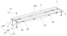
图1是本发明实施例的柔性支架的结构原理图;Fig. 1 is the structural principle diagram of the flexible support of the embodiment of the present invention;
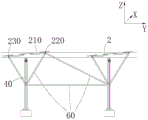
图2为图1的柔性支架的主视图;Fig. 2 is the front view of the flexible support of Fig. 1;
图3为图1的柔性支架的左视图;Fig. 3 is the left side view of the flexible bracket of Fig. 1;
图4为图2中A-A向的剖视图;Fig. 4 is the sectional view of A-A direction in Fig. 2;
图5为图1的柔性支架的俯视图;Fig. 5 is a top view of the flexible support of Fig. 1;
图6为本发明实施例的柔性支架的结构示意图;6 is a schematic structural diagram of a flexible stent according to an embodiment of the present invention;
图7为图6中B部分的放大图;Fig. 7 is an enlarged view of part B in Fig. 6;
图8为本发明实施例的的柔性支架遭遇横风时的受力示意图;Fig. 8 is a schematic diagram of the force of the flexible support in the embodiment of the present invention when it encounters a cross wind;
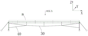
图9为本发明实施例的柔性支架的承受风压力的示意图;Fig. 9 is a schematic diagram of the wind pressure of the flexible support according to the embodiment of the present invention;
图10为本发明实施例的柔性支架的半刚性反拱索过松时的示意图;Fig. 10 is a schematic diagram when the semi-rigid anti-arch cable of the flexible bracket is too loose according to the embodiment of the present invention;
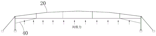
图11为本发明实施例的柔性支架的组件索因风吸力而变形的示意图;Fig. 11 is a schematic diagram showing the deformation of component cables of the flexible bracket due to wind suction according to the embodiment of the present invention;
图12为本发明实施例的半刚性反拱索的刚性部与节点件的装配示意图;Fig. 12 is a schematic diagram of the assembly of the rigid part and node parts of the semi-rigid anti-arch cable according to the embodiment of the present invention;
图13为本发明实施例的半刚性反拱索的刚性部与节点件的座体的组装图;Fig. 13 is an assembly diagram of the rigid part of the semi-rigid anti-arch cable and the base of the node part in the embodiment of the present invention;
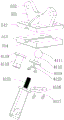
图14为图13所示组装体的爆炸图;Figure 14 is an exploded view of the assembly shown in Figure 13;
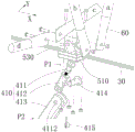
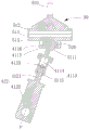
图15为图13所示组装体沿刚性部与节点件的对接方向的剖面示意图。FIG. 15 is a schematic cross-sectional view of the assembly shown in FIG. 13 along the butt joint direction of the rigid part and the node part.
图中的相关元件对应编号如下:The corresponding numbers of the relevant components in the figure are as follows:
1、柔性支架;10、支撑件;110、立柱;120、横梁;130、斜拉索;20、组件索;210、承载面;220、第一子索;230、第二子索;30、稳定索;40、半刚性反拱索;401、第一端;402、第二端;410、刚性部;411、第一连接件;4111、外球面;4112、球铰配合件;4113、套筒;4114、内腔;4115、螺纹孔段;4116、球铰端盖;4117、螺钉;4118、第一法兰盘;4119、第二法兰盘;412、第二连接件;4121、螺杆;4122、销孔、4123、限位件;413、索板;414、销轴;415、开口销;420、柔性拉索;50、节点件;510、座体;511、通孔;512、第一座体;513、第二座体;514、型槽;520、内球面;530、安装位;531、耳板;532、连接孔;60、桁杆;70、支撑节点;2、光伏组件;201、正面。1. Flexible support; 10. Support member; 110. Upright column; 120. Beam; 130. Stay cable; 20. Component cable; 210. Bearing surface; 220. First sub-cable; 230. Second sub-cable; Stability cable; 40, semi-rigid anti-arch cable; 401, first end; 402, second end; 410, rigid part; 411, first connector; 4111, outer spherical surface; Barrel; 4114, inner cavity; 4115, threaded hole section; 4116, spherical hinge end cover; 4117, screw; 4118, first flange; 4119, second flange; 412, second connector; 4121, screw ; 4122, pin hole, 4123, limit piece; 413, cable plate; 414, pin shaft; 415, cotter pin; 420, flexible cable; 50, node piece; The first seat; 513, the second seat; 514, the groove; 520, the inner spherical surface; 530, the installation position; 531, the ear plate; 532, the connection hole; 60, the truss; 70, the support node; Components; 201, front.
具体实施方式Detailed ways
为使本申请的上述目的、特征和优点能够更加明显易懂,下面结合附图对本申请的具体实施方式做详细的说明。在下面的描述中阐述了很多具体细节以便于充分理解本申请。但是本申请能够以很多不同于在此描述的其它方式来实施,本领域技术人员可以在不违背本申请内涵的情况下做类似改进,因此本申请不受下面公开的具体实施例的限制。In order to make the above-mentioned purpose, features and advantages of the present application more obvious and understandable, the specific implementation manners of the present application will be described in detail below in conjunction with the accompanying drawings. In the following description, numerous specific details are set forth in order to provide a thorough understanding of the application. However, the present application can be implemented in many other ways different from those described here, and those skilled in the art can make similar improvements without departing from the connotation of the present application, so the present application is not limited by the specific embodiments disclosed below.
在本申请实施例的描述中,术语“和/或”仅仅是一种描述关联对象的关联关系,表示可以存在三种关系,例如A和/或B,可以表示:单独存在A,同时存在A和B,单独存在B这三种情况。另外,本文中字符“/”,一般表示前后关联对象是一种“或”的关系。In the description of the embodiment of the present application, the term "and/or" is only a kind of association relationship describing associated objects, which means that there may be three kinds of relationships, such as A and/or B, which may mean: A exists alone, and A exists at the same time and B, there are three cases of B alone. In addition, the character "/" in this article generally indicates that the contextual objects are an "or" relationship.
本申请的实施例提供一种柔性支架,其中各实施例中以柔性支架承载光伏组件构成光伏系统为例进行说明。但可以理解地,本申请的柔性支架并不局限用以安装光伏组件。Embodiments of the present application provide a flexible support, and each embodiment is described by taking a photovoltaic system carried by a flexible support to form a photovoltaic system as an example. However, it can be understood that the flexible bracket of the present application is not limited to be used for installing photovoltaic modules.
请参照图1至图5,其中图1为本申请一些实施例的柔性支架1的结构示意图;图2为图1的柔性支架1的主视图;图3为图1的柔性支架1的左视图;图4为图1中A-A向的剖视图;图5为图1的柔性支架1的俯视图。Please refer to FIG. 1 to FIG. 5 , wherein FIG. 1 is a schematic structural view of a flexible bracket 1 according to some embodiments of the present application; FIG. 2 is a front view of the flexible bracket 1 of FIG. 1 ; FIG. 3 is a left side view of the flexible bracket 1 of FIG. 1 ; FIG. 4 is a cross-sectional view of A-A in FIG. 1 ; FIG. 5 is a top view of the flexible bracket 1 in FIG. 1 .
如图1和图2所示,本申请提供了一种柔性支架1。柔性支架1包括支撑件10、组件索20及稳定索30、半刚性反拱索40及节点件50。支撑件10沿第一方向X间隔设置至少两个,相邻两支撑件10之间安装有沿第一方向X的组件索20及稳定索30,其中组件索20形成承载面210(见图3)。如图2所示,半刚性反拱索40的第一端401与节点件50连接,半刚性反拱索40的第二端402与支撑件10连接。第一端401与节点件50连接,可以是固定连接,也可以是可相对活动地连接;且二者可以直接连接,或者通过居间元件连接。节点件50同时还与组件索20及稳定索30相连。柔性支架1的承载面210上安装有多个光伏组件2以构成光伏系统,多个光伏组件2设置于承载面210且沿第一方向X排列成排。As shown in FIG. 1 and FIG. 2 , the present application provides a flexible bracket 1 . The flexible support 1 includes a
支撑件10沿第一方向X间隔设置至少两个,图1至图3中仅示例性的绘出两个支撑件10。具体应用时,第一方向X可以是东西方向、南北方向或其他方向。进一步地,在第二方向Y上,光伏组件2可设置多排。如图1中所示,第二方向Y与第一方向X相交,及垂直于支撑件10的高度方向Z。There are at least two
示例性的,如图1所示,每一个支撑件10包括至少两个沿第二方向Y间隔设置的立柱110、连接两立柱110的横梁120。组件索20及稳定索30的两端分别与两横梁120相连。横梁120的长度可以设置为能够在第二方向Y上设置多处的组件索20及稳定索30,从而能够在第二方向Y上设置多排的光伏组件2。如图1中,示例性的示出了两排光伏组件2。进一步的,该示例中,每一个支撑件10的立柱110还与斜拉索130相连。斜拉索130用以连接至柔性支架1的安装基础(如地面),从而增加支撑件10的稳定性。较佳地,立柱110、横梁120的材质均选用钢材。较佳地,斜拉索130选用具有一定柔性的钢丝索,使用寿命长。Exemplarily, as shown in FIG. 1 , each supporting
组件索20沿第一方向X设置于相邻两支撑件10之间。例如,组件索20的两端分别与两横梁120相连。示例性的,参照图6和图7,其中图6为本发明一些实施例的柔性支架1的结构示意图;图7为图6中B部分的放大图。如图3和图7所示,组件索20包括第一子索220和第二子索230,第一子索220和第二子索230在第二方向Y上排列,且在支撑件10的高度方向上,第一子索220和第二子索230具有不同的高度。一具体实施方式中,第一子索220的两端连接于两横梁120的上部,而第二子索230的两端连接于两横梁120的下部,使第一子索220和第二子索230具有不同的高度。较佳地,组件索20选用具有一定柔性的钢丝索。The
参照图1、图3和图7,第一子索220和第二子索230具有不同的高度以使承载面210相对于水平面具有一定的角度,使得光伏组件2相对于水平面有一定角度,能够光伏组件2的正面201(受光面)更好地接收太阳光的照射。1, 3 and 7, the first sub-cable 220 and the second sub-cable 230 have different heights so that the bearing
具体地,如图3所示,在第二方向Y上,光伏组件2的两端高度不同。当第一方向X为东西方向时,则在南北方向上,光伏组件2的两端高度不同,从而光伏组件2的正面201能够朝向太阳,从而更好地接收太阳光的照射。Specifically, as shown in FIG. 3 , in the second direction Y, the heights of the two ends of the
本申请中,术语“风压力”指作用于光伏组件2的正面201的风载荷,方向竖直向下,此时载荷会以节点荷载的形式作用在组件索20上,再通过节点件50传递给稳定索30。另外,光伏组件2的正面201承受的载荷不限于风载荷,例如还包括雪荷载、积灰荷载等,此时稳定索30发挥同样的作用。术语“风吸力”指作用于光伏组件2的背面的风载荷,方向竖直向上,此时节点载荷通过节点件50传递给组件索20及半刚性反拱索40。In this application, the term "wind pressure" refers to the wind load acting on the
如图1和图2所示,稳定索30沿第一方向X设置于相邻两支撑件10之间。稳定索30用以在承受风压力时提供拉力,以保持组件索20的稳定性。较佳地,稳定索30选用具有一定柔性的钢丝索。示例性的,稳定索30的两端分别连接于两支撑件10的横梁120。As shown in FIG. 1 and FIG. 2 , the stabilizing
半刚性反拱索40的作用是在节点件50受风吸力时提供拉力,避免组件索20向上变形造成光伏组件2的破坏。通过设置稳定索30和半刚性反拱索40,本申请的柔性支架1抵抗风压力和风吸力的能力都较强,能够有效地防止结构的失稳,从而可以适应大跨度柔性支架1的设计和应用要求。The function of the semi-rigid
示例性的,参照图2,支撑件10的高度方向上,半刚性反拱索40的第一端401高于半刚性反拱索40的第二端402;稳定索30配置为开口向上的拱形。由此,稳定索30能够在承受风压力时提供拉力;半刚性反拱索40是斜向下设置,故其能够在节点件50受竖直向上的风吸力时提供拉力。Exemplarily, referring to FIG. 2, in the height direction of the
参照图1、图6和图7,节点件50连接稳定索30、半刚性反拱索40和组件索20,以形成一个较为稳定的支撑系统。节点件50可直接或者通过桁杆60与稳定索30、半刚性反拱索40和组件索20相连,其具体结构形式不限制。例如,节点件50可具有呈三角形分布的多个连接位,分别用于连接稳定索30、半刚性反拱索40和组件索20中的第一子索220和第二子索230。例如,连接位可直接与稳定索30等索相连,或者通过桁杆与稳定索30等索相连。Referring to Fig. 1, Fig. 6 and Fig. 7, the
参照图1、图7,半刚性反拱索40的第一端401具有与节点件50连接的刚性部410,半刚性反拱索40的第二端402与支撑件10连接。本申请中,半刚性指刚性+柔性的混合结构。例如,半刚性反拱索40可以包括相连接的刚性部410和柔性拉索420,从而构成半刚性结构。又例如,半刚性反拱索40可以包括柔性拉索420,柔性拉索420的部分区域构造为包覆有刚性部410。Referring to FIG. 1 and FIG. 7 , the
本申请中,柔性支架1的半刚性反拱索40的第一端401配置为具有刚性部410,通过刚性部410与节点件50连接。这样,半刚性反拱索40自身的刚性部410与节点件50二者构成的“节点连接部件”能够提供刚度,利于结构稳定。In the present application, the
另外,相关技术中,反拱索与节点件通过桁杆相连,桁杆固定于节点件使二者构成桁架,这种桁架是一个刚体,其质心和刚心存在第一偏差,由于桁杆通常长度较长,导致实际应用时当横风发生时,容易出现质心绕刚心转动的情况,即桁架有翻转的趋势。而本申请中,对于整个半刚性反拱索40而言,半刚性反拱索40是直接连接至节点件50,二者之间不需要设置较长的桁杆60相连。刚性部410直接连接至节点件50构成的“节点连接部件”也是一个刚体,但本申请通过省略较长的桁杆,获得了刚心和质心偏差小的刚体,即本申请的刚体的质心和刚心的第二偏差小于上述的第一偏差,故本申请的柔性支架1可以应对更大的横风,较相关技术的结构更为稳定。另外,本申请中,桁杆60、稳定索30及半刚性反拱索40均安装至节点件50,它们在同一节点安装,与相关技术中反拱索两端均连接至支撑件相比,可减少反拱索的索长度及节点件的数量,在满足承载需求的前提下既节省了索和节点件50的成本,也简化了安装步骤。In addition, in the related art, the anti-arch cable and the node parts are connected by truss rods, and the truss rods are fixed to the node parts to form a truss. This truss is a rigid body, and its center of mass and rigid center have the first deviation. The long length makes it easy for the center of mass to rotate around the center of rigidity when the cross wind occurs in practical applications, that is, the truss tends to overturn. In this application, however, for the entire semi-rigid
参照图1、图7,一些实施例中,半刚性反拱索40的刚性部410与节点件50可相对活动地连接。刚性部410与节点件50可相对活动,包括沿单一或多个方向的滑动,或者沿单一或多个方向的旋转。本申请中,柔性支架1的半刚性反拱索40的刚性部410与节点件50可相对活动地连接。这样,半刚性反拱索40自身的刚性部410与节点件50二者构成的“节点连接部件”一方面能够提供刚度,另一方面又能够适应风载荷的变化而发生变形,从而避免节点件50应力集中而被剪切破坏。Referring to FIG. 1 and FIG. 7 , in some embodiments, the
具体地,参照图8,图8为本申请的柔性支架1遭遇横风时的受力示意图。Specifically, referring to FIG. 8 , FIG. 8 is a schematic diagram of the force of the flexible support 1 of the present application when encountering a cross wind.
柔性支架1在使用时,正常情况下,光伏组件2仅承受风压力或风吸力,当光伏组件2承受风吸力时,反拱索承受的拉力位于一平面C内,该平面C是一竖直面且平行于第一方向X,图8中平面C垂直于图面。When the flexible support 1 is in use, under normal circumstances, the
然而,当遭遇如图8所示的横风F时,其中横风F指沿水平方向的风,其方向可以是沿本申请图1中的第二方向Y,此时光伏组件2会出现沿第一方向X和第二方向Y的偏移现象,如图8中,光伏组件2由位置I偏移至位置II,导致半刚性反拱索40将受到来自于平面C外的拉力。However, when encountering a crosswind F as shown in Figure 8, where the crosswind F refers to the wind along the horizontal direction, its direction can be along the second direction Y in Figure 1 of the present application, at this time the
当本申请的实施例的柔性支架1遭遇沿第二方向Y的横风时,参照图6和图7,由于刚性部410与节点件50可相对活动,节点件50跟随光伏组件2一起运动时也相对刚性部410活动,从而避免节点件50与刚性部410发生剪力,继而避免节点件50损坏。When the flexible bracket 1 of the embodiment of the present application encounters a cross wind along the second direction Y, referring to Fig. 6 and Fig. 7, since the
上述实施例中,以横风F的方向刚好沿第二方向Y为例进行说明。但应当认识到,横风的方向可能是其他方向,例如,参照图8,横风F的方向与第二方向Y呈锐角,如沿水平方向斜向上。此时,通过刚性部410与节点件50可相对活动连接,横风F在第二方向Y上的分力将使得光伏组件2由图8中的位置I偏移至位置II,此时节点件50跟随光伏组件2一起运动时也相对刚性部410活动,避免节点件50与刚性部410发生剪力,继而避免节点件50损坏。In the above embodiments, the direction of the cross wind F is just along the second direction Y as an example for illustration. However, it should be recognized that the direction of the crosswind may be other directions. For example, referring to FIG. 8 , the direction of the crosswind F forms an acute angle with the second direction Y, such as obliquely upward along the horizontal direction. At this time, the
另外,如前文所述,本申请通过省略较长的桁杆,获得了刚心和质心偏差小的刚体,即本申请的刚体的质心和刚心的第二偏差小于上述的第一偏差,故本申请的柔性支架1可以应对更大的横风,较相关技术的结构更为稳定;并且,即使出现质心绕刚心转动的情况,刚性部410可相对节点件50活动也可适应这种转动,避免节点件50轻易损坏。In addition, as mentioned above, the present application obtains a rigid body with a small deviation of the center of rigidity and the center of mass by omitting the longer truss, that is, the second deviation of the center of mass and the center of rigidity of the rigid body of the present application is smaller than the above-mentioned first deviation, so The flexible support 1 of the present application can cope with greater cross winds, and is more stable than the structure of the related art; and, even if the center of mass rotates around the center of rigidity, the
此外,如图1所示,半刚性反拱索40的两端分别与节点件50和支撑件10相连。通过这种方式,半刚性反拱索40的中间部分不与其他索或者支撑件相连,可以仅在稳定索30在首尾处设置半刚性反拱索40,这样半刚性反拱索40的长度较短,在保证稳定性的前提下降低了索成本。具体设置时,节点件50设置为靠近支撑件10也即稳定索30的首或尾处,半刚性反拱索40无需自一个支撑件10延伸至相邻的另一个支撑件10,长度较短。In addition, as shown in FIG. 1 , the two ends of the semi-rigid
一些实施例中,参照图2,稳定索30的位于节点件50与支撑件10之间的部分的长度为L1,稳定索30的总长度为L2,其中L1/L2的范围为1/5-1/4。本申请中,稳定索30的总长度L2指第一方向X上相邻两支撑件10之间的稳定索30的长度。In some embodiments, referring to FIG. 2 , the length of the part of the stabilizing
节点件50与支撑件10之间的稳定索30的长度L1,与节点件50在稳定索30的位置有关。L1/L2又可称为节点件50在稳定索30上的跨度,即节点件50在稳定索30上的跨度为1/5-1/4。The length L1 of the stabilizing
参照图2,自首或尾处朝向稳定索30的中部,稳定索30的内应力呈减小的趋势,通过将节点件50在稳定索30上的跨度为1/5-1/4,既可以保证对稳定索30中段的支撑,又避免半刚性反拱索40的长度过长。With reference to Fig. 2, toward the middle part of stabilizing
根据本申请的一些实施例,参照图6和图7,刚性部410与节点件50至少在第二方向Y上能够相对活动,第二方向Y垂直于第一方向X,且第二方向Y垂直于支撑件10的高度方向Z。例如,刚性部410与节点件50在第二方向Y上能够相对滑动或者相对旋转。例如,第一方向X为东西方向,则第二方向Y为南北方向。According to some embodiments of the present application, referring to FIG. 6 and FIG. 7, the
柔性支架1使用时,多个光伏组件2沿第一方向X排列成排,沿第二方向Y呈多排设置。一般地,横风的方向沿第二方向Y。这样,柔性支架1使用时即使遭遇这种横风时,也仍能保持较好的稳定性。When the flexible support 1 is used, a plurality of
根据本申请的一些实施例,参照图6和图7,刚性部410与节点件50至少在支撑件10的高度方向Z上能够相对活动。这样,参照图8,当柔性支架1使用时遭遇的横风F在支撑件10的高度方向Z上存在分力时,刚性部410与节点件50在支撑件10的高度方向Z上能够相对活动,避免节点件50与刚性部410发生剪力,继而避免节点件50损坏。较佳地,刚性部410与节点件50配置为能够在第二方向Y上相对活动,及能够在第一方向X上相对活动。例如,刚性部410可设置为与节点件50的连接处在第二方向Y上相对活动,该连接处相对于节点件50又可在第一方向X上相对活动。这样,柔性支架1使用时遭遇沿第一方向X或第二方向Y的横风时,均能保持较好的稳定性。According to some embodiments of the present application, referring to FIG. 6 and FIG. 7 , the
根据本申请的一些实施例,参照图7,刚性部410与节点件50以球面副配合以能够相对活动。例如,刚性部和节点件二者中之一设有外球面,二者中之另一设有内球面,外球面与内球面配合从而形成球面副配合。According to some embodiments of the present application, referring to FIG. 7 , the
刚性部410与节点件50以球面副配合,二者能够在包括第一方向X、第二方向Y及支撑件10的高度方向Z在内的任意方向上相对活动。故柔性支架1能够抵抗任意方向的横风。在安装柔性支架1时,只需要考虑如何使光伏组件2最大限度的采光即可,无需考虑环境中横风的方向,从而提高了柔性支架1使用的便捷性。The
根据本申请的一些实施例,参照图1、图7、半刚性反拱索40包括刚性部410、与刚性部410相连的柔性拉索420,刚性部410与节点件50活动连接,柔性拉索420与支撑件10连接。柔性拉索420与刚性部410可借助固定结构相连接或者利用刚高强度胶粘结。较佳地,柔性拉索420选用具有一定柔性的钢丝。According to some embodiments of the present application, referring to Fig. 1 and Fig. 7, the semi-rigid
刚性部410与柔性拉索420相连接形成半刚性结构,其中刚性部410与节点件50相连形成刚体以支撑柔性拉索420,且刚性部410与节点件50可相对活动,节点件50跟随光伏组件2一起运动时也相对刚性部410活动,从而避免与刚性部410发生剪力,继而避免节点件50损坏。此外,刚性部410与柔性拉索420相连接形成半刚性结构,制备时,可以基于现有的柔性拉索而得到,不需要制备非标的柔性拉索,利于降低成本。刚性部410与柔性拉索420固定连接在一起,具体方式不限制。示例性的,刚性部410可通过锚具与柔性拉索420相连。The
如前文所述,刚性反拱索自身的刚性部410与节点件50一起构成“节点连接部件”,同时刚性部410可相对节点件50活动,从而“节点连接部件”一方面能够提供刚度,另一方面又能够适应风载荷的变化而发生变形,从而避免节点件50应力集中而被剪切破坏。并且,节点连接部件的质心和刚心的偏差小,结构稳定。As mentioned above, the
此外,参照图9,图9为本发明实施例的柔性支架1的承受风压力的示意图。如图9所示,风吸力的方向通常竖直向上,即垂直于底面向上。然而实际应用时,风吸力的方向也经常出现不垂直与地面的情况。此时,由于刚性部410与节点件50以球面副配合,节点件50能够根据风向调整位置,避免节点件50因为剪切力而轻易损坏。In addition, referring to FIG. 9 , FIG. 9 is a schematic diagram of the wind pressure of the flexible support 1 according to the embodiment of the present invention. As shown in FIG. 9 , the direction of the wind suction is usually vertically upward, that is, perpendicular to the bottom surface upward. However, in practical applications, the direction of wind suction is often not perpendicular to the ground. At this time, since the
参照图10和图11,图10为本发明实施例的柔性支架1的半刚性反拱索40过松时的示意图;图11为本发明实施例的柔性支架1的组件索20因风吸力而变形的示意图。Referring to Fig. 10 and Fig. 11, Fig. 10 is a schematic diagram of when the semi-rigid
半刚性反拱索40用于在柔性支架1受风吸力时提供拉力,避免组件索20向上变形而造成光伏组件2损坏,因此半刚性反拱索40的松紧度是否合适非常重要。然而半刚性反拱索40是在节点件50既不受风压力也不受风吸力的常规条件下安装的,过松时就会出现图11所示的变形情况,过紧时又会影响节点件50的寿命。The semi-rigid
针对上述问题,本申请提供一种半刚性反拱索40的松紧度调节的解决方案。具体而言,参照图7,刚性部410配置为长度可调节。将半刚性反拱索40自身的刚性部设置为长度可调节,能够实现半刚性反拱索40的松紧度的调节。例如,刚性部410包括可伸缩部分及固定部分,如伸缩部分可为伸缩管,固定部分为卡扣机构用以限位伸缩管,从而实现长度调节的目的。In view of the above problems, the present application provides a solution for adjusting the tightness of the semi-rigid
通过使刚性部410的长度可调节,可在安装完毕半刚性反拱索40后,可以测试其松紧度,根据需要拓展刚性部410的长度,从而适应多变的环境需求,防止半刚性反拱索40过松而丧失风吸下的保护能力。By making the length of the
此外,请参考图8,当遭遇沿第二方向Y的横风时,第二方向Y上各光伏组件2承受的风力不同,位移量将不同,此时可以单独调整各刚性反拱索的长度,从而更好地适应上述位移量不同的工况,保证支架结构稳定。In addition, please refer to Fig. 8, when encountering a cross wind along the second direction Y, the wind force of each
根据本申请的一些实施例,参照图12,其中图12为本发明实施例的半刚性反拱索40的刚性部410与节点件50的装配示意图。如图12所示,节点件50包括座体510。座体510上连接有多根桁杆60。多根桁杆60分别用于连接组件索20或者用于与相邻的节点件50相连。座体510与稳定索30相连,及与半刚性反拱索40相连。在其他的实施方式中,座体510的形状可直接设置为使座体510能够与组件索20相连,从而无需另外设置桁杆。According to some embodiments of the present application, refer to FIG. 12 , wherein FIG. 12 is a schematic diagram of the assembly of the
根据本申请的一些实施例,参照图13至图15,其中图13为本发明实施例的半刚性反拱索40的刚性部410与节点件50的座体510的组装图;图14为图13所示组装体的爆炸图;图15为图13所示组装体沿刚性部410与节点件50的对接方向的截面示意图。According to some embodiments of the present application, refer to Fig. 13 to Fig. 15, wherein Fig. 13 is an assembly diagram of the
一些实施例中,参照图13和图14,为方便装配,刚性部410包括可拆卸连接的第一连接件411和第二连接件412,其中第一连接件411与节点件50活动连接,第二连接件412与索板413连接,索板413可通过锚具(未图示)与柔性拉索420相连。具体地,第二连接件412和索板413上分别设有销孔4122,二者通过销轴414和开口销415固定或活动连接。In some embodiments, referring to Fig. 13 and Fig. 14, for the convenience of assembly, the
一些实施例中,刚性部410与节点件50以球面副配合以能够相对活动。具体而言,如图15所示,刚性部410和节点件50二者中之一设有外球面4111,二者中之另一设有内球面520,外球面4111与内球面520配合从而形成球面副配合。示例性的,节点件50设有具有内球面520的球窝(未标号),刚性部410设有具有外球面4111的球铰配合件4112,球铰配合件4112插入到球窝中。In some embodiments, the
根据本申请的一些实施例,参照图7和图12,刚性部410包括构成螺旋配合副的第一连接件411和第二连接件412,第一连接件411与节点件50活动连接,第二连接件412用以与支撑件10连接。具体地,参照图12,第二连接件412与柔性拉索420通过索板413连接,通过柔性拉索420与支撑件10相连接。通过螺旋配合的方式实现刚性部410长度的调节,具体调节时使第一连接件411和第二连接件412相对旋转即可,操作便利,利于实现快速调节。According to some embodiments of the present application, referring to Fig. 7 and Fig. 12, the
一些实施例中,参照图12,半刚性反拱索40的刚性部410包括第一部分P1、与第一部分P1活动连接的第二部分P2,第一部分和节点件50相连,第二部分与所述支撑件10连接。In some embodiments, referring to FIG. 12 , the
示例性的,第一部分P1包括构成螺旋配合副的第一连接件411和第二连接件412。第二部分P2包括索板413。索板413长度方向上的一端与柔性拉索420相连。具体地,索板413可通过锚具与柔性拉索相连。索板413长度方向上的另一端与第二连接件412固定连接或可相对转动连接。具体地,参照图12和图13,第二连接件412和索板413上分别设有销孔4122,二者通孔511销轴414和开口销415连接。索板413与第二连接件412可相对转动地连接时,可以是沿第一方向X或第二方向Y可相对转动地连接;且索板413与第二连接件412沿第一方向X或第二方向Y可相对转动地连接的方案,与刚性部410与节点件50在第一方向X及/或第二方向Y上相对活动的方案可任意组合使用,从而能够更好地使柔性支架1抵抗横风。例如,索板413与第二连接件412沿第二方向Y,同时刚性部410与节点件50在第二方向Y可相对活动。如此,当遭遇第二方向Y的横风时,刚性部410与节点件50在第二方向Y可相对活动以避免节点件50与刚性部410发生剪切,同时索板413与第二连接件412在第二方向Y上可相对活动,使得柔性拉索420与索板413的之间也可以适应横风而活动,能够减小柔性拉索420与索板413之间的磨损。刚性部410的第一部分P1、第二部分P2活动连接,能够适应横风而活动,减少两部分之间磨损。Exemplarily, the first part P1 includes a first connecting
可理解地,第一部分P1和第二部分P2的具体结构没有限制。在其他的实施方式中,第一部分P1不限于设置为包括构成螺旋配合副的第一连接件411和第二连接件412。例如,第一部分P1可以设置为不可以长度调节。又例如,第一部分P1与节点件50可以相对活动连接外,还可以是固定连接。Understandably, the specific structures of the first part P1 and the second part P2 are not limited. In other embodiments, the first part P1 is not limited to be configured to include the first connecting
一些实施例中,参照图14和图15,第一连接件411与节点件50相连,具体地与座体510相连。第一连接件411包括套筒4113、设于套筒4113首端的球铰配合件4112,套筒4113的内腔4114设有螺纹孔段4115,球铰配合件4112具有外球面4111。对应地,节点件50的座体510上设有具有内球面520区域的球窝(未标号)。球铰配合件4112插入到球窝中以使第一连接件411与节点件50的座体510构成球面配合副。具体地,球铰配合件4112插入到球窝中,且通过球铰端盖4116和螺钉4117固定在座体510上。可以理解,内球面520和外球面4111二者的位置也可以互换。In some embodiments, referring to FIG. 14 and FIG. 15 , the first connecting
第二连接件412包括与螺纹孔段4115配合的螺杆4121。螺杆4121与螺纹孔段4115螺纹配合,以使得第二连接件412与第一连接件411构成螺旋配合副。The second connecting
通过上述方式,第一连接件411与第二连接件412构成螺旋配合副,且第一连接件411与节点件50的座体510构成球面配合副。螺旋配合副和球面配合副配合使用可方便地实现半刚性反拱索40松紧度的调整。In the manner described above, the first connecting
具体地,参考图7和图15,调节半刚性反拱索40的松紧度的过程简述如下:球铰配合件4112可以相对座体510转动,故套筒4113可以绕套筒4113的轴线P旋转。需要调节半刚性反拱索40的松紧度时,旋转套筒4113使其轴线P旋转,与套筒4113螺旋配合的螺杆4121在柔性拉索420的限制下只能作直线运动,从而拉紧柔性拉索420或放松柔性拉索420,实现半刚性反拱索40的松紧度的调节。Specifically, with reference to Fig. 7 and Fig. 15, the process of adjusting the tightness of the semi-rigid
另外,第一连接件411与节点件50的座体510构成球面配合副,该球面配合副除了与第一连接件411与第二连接件412构成的螺旋配合副相配合使用实现半刚性反拱索40松紧度的调整外,如前文所述,该球面配合副还使得柔性支架1具有抵抗任意方向横风的能力。即球面配合副同时用以实现半刚性反拱索40松紧度的调整,及用以实现柔性支架1抵抗横风,简化柔性支架1的结构。In addition, the first connecting
参照图14和图15,为避免调节半刚性反拱索40的松紧度时,第二连接件412和第一连接件411意外脱离;第二连接件412的螺杆4121上还设有限位件4123,限位件4123配置为用以防止螺杆4121自套筒4113中脱离。Referring to Fig. 14 and Fig. 15, in order to avoid the accidental disengagement of the second connecting
利用限位件4123实现防脱的方式有多种。例如,限位件4123位于螺纹孔段4115的靠近节点件50的一侧,在套筒4113的径向上,限位件4123的尺寸大于螺纹孔段4115的内径,从而能够阻止螺杆4121从套筒4113脱离。又例如,套筒4113的内腔4114中设有用以轴向阻挡限位件4123的阻挡结构。该阻挡结构具体可以是设置在内腔4114的内壁上的环形台阶。通过设置限位件4123配置为用以防止螺杆4121自套筒4113中脱离,避免调节半刚性反拱索40的松紧度时,第二连接件412和第一连接件411意外脱离,继而避免柔性支架1失稳。There are many ways to use the
一些实施例中,参照图15,在套筒4113的轴向上,球铰配合件4112可拆卸地设置于套筒4113的轴向上的首端(未标号),螺纹孔段4115设于套筒4113的轴向上的尾端(未标号),限位件4123可拆卸地设置于螺杆4121,限位件4123的尺寸大于螺纹孔段4115的内径。In some embodiments, referring to Fig. 15, in the axial direction of the
通过上述方式,限位件4123相对套筒4113沿套筒4113的轴向移动时,限位件4123不能够从螺纹孔段4115中穿过,限位件4123可阻止螺杆4121远离节点件50运动时自套筒4113中脱离,从而避免调节半刚性反拱索40的松紧度时第二连接件412和第一连接件411意外脱离。Through the above method, when the limiting
在实现防脱功能的前提下,通过将球铰配合件4112可拆卸地设置于套筒4113的首端,限位件4123可拆卸地设置于螺杆4121,还方便了第一连接件411和第二连接件412的装配。具体而言,装配时,先将螺杆4121自套筒4113的首端伸入套筒4113的内腔4114并且螺纹孔段4115实现螺纹连接,然后将限位件4123安装在螺杆4121上,最后再将球铰配合件4112安装至套筒4113的首端从而将套筒4113的首端封闭。On the premise of realizing the anti-off function, the ball
较佳地,螺杆4121的长度设置为大于套筒4113的轴向长度。这样,螺杆4121自套筒4113的尾端伸入套筒4113后可以再伸出套筒4113的首端,从而具有较大的操作空间以方便安装限位件4123。Preferably, the length of the
一些实施例中,参照图14和图15,套筒4113的首端设有第一法兰盘4118。球铰配合件4112设有第二法兰盘4119。第二法兰盘4119通过紧固件(未标号)可拆卸地连接至第一法兰盘4118。球铰配合件4112与套筒4113的连接不限于此,如还可以通过卡扣连接、销连接等。套筒4113与球铰配合件4112通过两兰盘对接,能够迅速对准继而完成组装。In some embodiments, referring to FIG. 14 and FIG. 15 , the first end of the
限位件4123的具体形状和安装方式不限制。例如,限位件4123可安装在螺杆4121的端部并通过螺钉固定。又例如,限位件4123为通过过盈配合而套设在螺杆4121上且与螺杆4121固定连接的板状结构。The specific shape and installation method of the limiting
根据本申请的一些实施例,参照图1和图6,节点件50位置可调地安装于稳定索30。例如,节点件50的座体510与稳定索30可拆卸地固定连接。如此,节点件50可以在稳定索30自由调节安装位置,能够用于调节半刚性反拱索40的松紧度。并且,节点件50的位置调整还可以配合刚性部410的长度调节来更方便地实现半刚性反拱索40的松紧调节。According to some embodiments of the present application, referring to FIG. 1 and FIG. 6 , the
一些实施例中,参照图1和图6,稳定索30与节点件50摩擦连接。摩擦连接指定稳定索30与节点件50通过摩擦力实现相对定位。例如,节点件50上设有卡槽,利用卡槽与稳定索30之间的摩擦力对稳定索30进行定位。需要调节节点件50的位置时,使节点件50克服摩擦力相对稳定索30运动即可,无拆卸动作,操作效率高。In some embodiments, referring to FIGS. 1 and 6 , the stabilizing
参照图12和图13所示,示例性的,节点件50的座体510设有通孔511,稳定索30穿设于通孔511中,稳定索30的外径与通孔511的内孔相匹配,从而使稳定索30与节点件50摩擦连接。这种方式便于实现节点件50安装位置的调整,且通过取消采用螺栓连接稳定索30与支架而简化固定方案。Referring to Figures 12 and 13, exemplary, the
如图13和图14所示,示例性的,座体510包括可拆卸地对接配合的第一座体512和第二座体513,第二座体513与第一座体512围成通孔511。由此,可在第一座体512和第二座体513处于分离状态下方便地安装稳定索30。具体而言,第一座体512和第二座体513各设有用于组成上述通孔511的型槽514(如半圆形槽),第一座体512和第二座体513对接后才形成完整的通孔511。安装稳定索30时,将稳定索30放入第一座体512或第二座体513上的型槽514内,然后再通过螺栓连接第一座体512和第二座体513。较直接将稳定索30穿入通孔511相比,无需轴向将稳定索30与通孔511精准地对准,操作方便,安装效率高。As shown in FIG. 13 and FIG. 14 , exemplary, the
根据本申请的一些实施例,参照图6、图7和图12,柔性支架1还包括连接至安装位530的桁杆60,部分的桁杆60与组件索20相连;沿第二方向,相邻的节点件50通过至少一桁杆60互联,第二方向Y垂直于第一方向X及垂直于所述支撑件的高度方向Z。According to some embodiments of the present application, referring to FIG. 6 , FIG. 7 and FIG. 12 , the flexible support 1 further includes a
示例性的,节点件50包括若干个设置座体510的安装位530。安装位530上安装有多根桁杆60。Exemplarily, the
一较佳的实施方式中,安装位530包括突设于座体510的耳板531,每个耳板531上设有连接孔532;桁杆60安装至连接孔532。具体而言,桁杆60可通过螺钉4117或其他合适的紧固件安装至连接孔532。耳板531突出座体510设置,在安装桁杆60时具有较大的操作空间。In a preferred embodiment, the mounting
进一步地,参照图12至图14,耳板531沿第二方向Y间隔设有两处,连接孔532沿第二方向Y贯穿耳板531。这样,每个耳板531在第二方向Y上的两侧可分别安装桁杆60且可公用一套紧固件以简化结构。这样每个座体510可连接四根桁杆60。Further, referring to FIG. 12 to FIG. 14 , the
参照图6、图7和图12,在第二方向Y上,光伏组件2设置有多排。四根桁杆60中的a和b,可以用于连接组件索20的第一子索220和第二子索230。四根桁杆60中的c和d可用以实现第二方向Y上相邻两节点件50的互联。这样,只需要使用一个节点件50的座体510即可以连接多达四根桁杆60,从而实现与组件索20的连接,及第二方向Y上相邻两节点件50的互联。不同节点件50连接后,既在平面内提供一榀刚度,又将载荷分散至多个受力片区,从而在大跨度场景下也保持较好的稳定性。Referring to FIG. 6 , FIG. 7 and FIG. 12 , in the second direction Y,
具体地,如图6所示,第二方向Y上,多个节点件50互联而形成一索桁架,从而提供一榀刚度;同时,在第一方向X上,形成了多个这样的索桁架。如图9所示,当光伏组件2受到风压力时,多个索桁架在第一方向X上,形成多个受力片区m来分散承担载荷,单个受力片区m的受力较小,从而利于增加柔性支架1的跨度,即第一方向X上的长度。上述的受力片区m形成于相邻的索桁架之间、及索桁架与支撑件10之间。Specifically, as shown in Figure 6, on the second direction Y, a plurality of
上述实施例,通过在节点件50上设置多根桁杆,同时实现与组件索20的连接,及在第二方向Y上相邻节点件50的互联,从而建立支撑组件索20、稳定索30及半刚性反拱索40的稳定系统的同时,还在第一方向X上,形成多个受力片区m来分散承担载荷,从而利于增加柔性支架1的跨度。In the above-mentioned embodiment, by arranging multiple trusses on the
根据本发明的一些实施例,参考图1,沿第一方向X,稳定索30的首尾处均设有的节点件50和半刚性反拱索40,稳定索30的中段通过支撑节点70与组件索20相连。According to some embodiments of the present invention, with reference to FIG. 1 , along the first direction X,
刚性反拱索仅设置在稳定索30在首尾处设置半刚性反拱索40,半刚性反拱的长度较短,在保证稳定性的腔体下降低了索成本。稳定索30的中段则通过一个或多个的支撑节点70连接至组件索20,提高稳定中段的抗风能力。稳定索30的中段指稳定索30的位于两节点件50之间的部分。The rigid anti-arch cable is only arranged on the
进一步地,稳定索30的中段与支撑节点70摩擦连接。这里的摩擦连接,与稳定索30与节点件50的摩擦连接方式可以完全相同,故不再赘述。如此,可以根据需调整支撑节点70在稳定索30的中段的位置,利于提高稳定中段的抗风能力。Further, the middle section of the stabilizing
根据本申请的一些实施例,如图1所示,还提出一种光伏系统。光伏系统包括上述任一实施例的柔性支架1、若干光伏组件2,若干光伏组件2安装于所述承载面210。According to some embodiments of the present application, as shown in FIG. 1 , a photovoltaic system is also provided. The photovoltaic system includes the flexible support 1 of any of the above-mentioned embodiments, several
上述光伏系统,柔性支架1的半刚性反拱索40的第一端401配置为具有刚性部410。这样,半刚性反拱索40自身的刚性部410与节点件50一起构成“节点连接部件”,一方面能够提供刚度,另一方面“节点连接部件”的刚心和质心二者偏差小,不容易翻转,因此本申请的柔性支架1结构更为稳定,从而保障光伏系统正常工作。此外,刚性部410与节点件50可设置为相对活动地连接,还能够适应风载荷的变化而发生变形,从而避免节点件50应力集中而被剪切破坏;使柔性支架1结构更为稳定。In the aforementioned photovoltaic system, the
以上所述实施例的各技术特征可以进行任意的组合,为使描述简洁,未对上述实施例中的各个技术特征所有可能的组合都进行描述,然而,只要这些技术特征的组合不存在矛盾,都应当认为是本说明书记载的范围。The technical features of the above-mentioned embodiments can be combined arbitrarily. To make the description concise, all possible combinations of the technical features in the above-mentioned embodiments are not described. However, as long as there is no contradiction in the combination of these technical features, should be considered as within the scope of this specification.
在本申请的描述中,术语“第一”、“第二”仅用以描述目的,而不能理解为指示或暗示相对重要性或者隐含指明所指示的技术特征的数量。由此,限定有“第一”、“第二”的特征可以明示或者隐含地包括至少一个该特征。在本申请实施例的描述中,术语“多个”指的是两个以上(包括两个),同理,“多组”指的是两组以上(包括两组)。In the description of the present application, the terms "first" and "second" are used for descriptive purposes only, and cannot be understood as indicating or implying relative importance or implicitly indicating the quantity of indicated technical features. Thus, the features defined as "first" and "second" may explicitly or implicitly include at least one of these features. In the description of the embodiments of the present application, the term "multiple" refers to two or more (including two), and similarly, "multiple groups" refers to two or more groups (including two).
在本申请中,除非另有明确的规定和限定,术语“安装”、“相连”、“连接”、“固定”等术语应做广义理解,例如,可以是固定连接,也可以是可拆卸连接,或成一体;可以是机械连接,也可以是电连接;可以是直接相连,也可以通过中间媒介间接相连,可以是两个元件内部的连通或两个元件的相互作用关系,除非另有明确的限定。对于本领域的普通技术人员而言,可以根据具体情况理解上述术语在本申请中的具体含义。In this application, terms such as "installation", "connection", "connection" and "fixation" should be interpreted in a broad sense, for example, it can be a fixed connection or a detachable connection, unless otherwise clearly specified and limited. , or integrated; it may be mechanically connected or electrically connected; it may be directly connected or indirectly connected through an intermediary, and it may be the internal communication of two components or the interaction relationship between two components, unless otherwise specified limit. Those of ordinary skill in the art can understand the specific meanings of the above terms in this application according to specific situations.
在本申请中,除非另有明确的规定和限定,第一特征在第二特征“上”或“下”可以是第一和第二特征直接接触,或第一和第二特征通过中间媒介间接接触。而且,第一特征在第二特征“之上”、“上方”和“上面”可是第一特征在第二特征正上方或斜上方,或仅仅表示第一特征水平高度高于第二特征。第一特征在第二特征“之下”、“下方”和“下面”可以是第一特征在第二特征正下方或斜下方,或仅仅表示第一特征水平高度小于第二特征。In the present application, unless otherwise clearly specified and limited, a first feature being "on" or "under" a second feature may mean that the first and second features are in direct contact, or that the first and second features are indirect through an intermediary. touch. Moreover, "above", "above" and "above" the first feature on the second feature may mean that the first feature is directly above or obliquely above the second feature, or simply means that the first feature is higher in level than the second feature. "Below", "beneath" and "beneath" the first feature may mean that the first feature is directly below or obliquely below the second feature, or simply means that the first feature is less horizontally than the second feature.
以上所述实施例仅表达了本申请的几种实施方式,其描述较为具体和详细,但并不能因此而理解为对申请专利范围的限制。应当指出的是,对于本领域的普通技术人员来说,在不脱离本申请构思的前提下,还可以做出若干变形和改进,这些都属于本申请的保护范围。因此,本申请专利的保护范围应以所附权利要求为准。The above-mentioned embodiments only express several implementation modes of the present application, and the description thereof is relatively specific and detailed, but should not be construed as limiting the scope of the patent application. It should be noted that those skilled in the art can make several modifications and improvements without departing from the concept of the present application, and these all belong to the protection scope of the present application. Therefore, the scope of protection of the patent application should be based on the appended claims.
Claims (20)
Priority Applications (5)
| Application Number | Priority Date | Filing Date | Title |
|---|---|---|---|
| CN202211536745.0A CN115864951B (en) | 2022-12-02 | 2022-12-02 | Photovoltaic system and its flexible support |
| AU2023404430A AU2023404430A1 (en) | 2022-12-02 | 2023-10-25 | Photovoltaic system and flexible bracket thereof |
| PCT/CN2023/126479 WO2024114188A1 (en) | 2022-12-02 | 2023-10-25 | Photovoltaic system and flexible bracket thereof |
| US18/873,621 US20250330117A1 (en) | 2022-12-02 | 2023-10-25 | Photovoltaic system and flexible bracket thereof |
| EP23896343.3A EP4521630A4 (en) | 2022-12-02 | 2023-10-25 | PHOTOVOLTAIC SYSTEM AND FLEXIBLE MOUNTING FOR IT |
Applications Claiming Priority (1)
| Application Number | Priority Date | Filing Date | Title |
|---|---|---|---|
| CN202211536745.0A CN115864951B (en) | 2022-12-02 | 2022-12-02 | Photovoltaic system and its flexible support |
Publications (2)
| Publication Number | Publication Date |
|---|---|
| CN115864951A true CN115864951A (en) | 2023-03-28 |
| CN115864951B CN115864951B (en) | 2024-12-31 |
Family
ID=85669263
Family Applications (1)
| Application Number | Title | Priority Date | Filing Date |
|---|---|---|---|
| CN202211536745.0A Active CN115864951B (en) | 2022-12-02 | 2022-12-02 | Photovoltaic system and its flexible support |
Country Status (5)
| Country | Link |
|---|---|
| US (1) | US20250330117A1 (en) |
| EP (1) | EP4521630A4 (en) |
| CN (1) | CN115864951B (en) |
| AU (1) | AU2023404430A1 (en) |
| WO (1) | WO2024114188A1 (en) |
Cited By (3)
| Publication number | Priority date | Publication date | Assignee | Title |
|---|---|---|---|---|
| CN116722809A (en) * | 2023-08-11 | 2023-09-08 | 天合光能股份有限公司 | Flexible tracking bracket and photovoltaic power station |
| CN116886009A (en) * | 2023-07-06 | 2023-10-13 | 汇耀品尚能源科技(嘉兴)有限公司 | A flexible photovoltaic bracket |
| WO2024114188A1 (en) * | 2022-12-02 | 2024-06-06 | 天合光能股份有限公司 | Photovoltaic system and flexible bracket thereof |
Families Citing this family (4)
| Publication number | Priority date | Publication date | Assignee | Title |
|---|---|---|---|---|
| CN118559386B (en) * | 2024-07-29 | 2024-10-01 | 江苏曦日新能源科技有限公司 | Photovoltaic board installs supporting device suitable for flexible photovoltaic support |
| CN119010746B (en) * | 2024-10-18 | 2025-05-13 | 汇耀品尚能源科技(嘉兴)有限公司 | End bracket structure and flexible photovoltaic bracket system |
| CN119178951B (en) * | 2024-11-25 | 2025-02-28 | 苏州隐冠半导体技术有限公司 | A testing device and a testing method for a piezoelectric device |
| CN119276205B (en) * | 2024-12-12 | 2025-07-29 | 汇耀品尚能源科技(嘉兴)有限公司 | Photovoltaic support and flexible tracking photovoltaic system |
Citations (16)
| Publication number | Priority date | Publication date | Assignee | Title |
|---|---|---|---|---|
| GB690658A (en) * | 1951-02-28 | 1953-04-22 | Leonard Peter Frieder | Readily demountable truss |
| RU2528311C1 (en) * | 2013-07-05 | 2014-09-10 | Федеральное государственное бюджетное образовательное учреждение высшего профессионального образования "Тольяттинский государственный университет" (ТГУ) | Polysystemic truss |
| CN204530991U (en) * | 2015-04-20 | 2015-08-05 | 中国航空规划建设发展有限公司 | A kind of large-span prestressed arch truss and rope film combining structure |
| EA201600648A1 (en) * | 2016-08-29 | 2018-03-30 | Частное проектное унитарное предприятие "Моноракурс" | SPATIAL VANTY FARM |
| KR20200009277A (en) * | 2018-07-18 | 2020-01-30 | 주식회사 택한 | Cable support structure for photovoltaic solar panels |
| WO2021009742A1 (en) * | 2019-07-18 | 2021-01-21 | Palziv Ein Hanaziv Agricultural Cooperative Society Ltd. | Photovoltaic device and system |
| CN113904616A (en) * | 2021-12-09 | 2022-01-07 | 深圳市安泰科能源环保股份有限公司 | Flexible photovoltaic support |
| CN114250907A (en) * | 2021-12-29 | 2022-03-29 | 中建科工集团有限公司 | Beam string structure |
| CN114337501A (en) * | 2022-01-25 | 2022-04-12 | 长江勘测规划设计研究有限责任公司 | Arch flexible photovoltaic supporting structure who supports |
| CN216490304U (en) * | 2022-03-18 | 2022-05-10 | 深圳市安泰科柔性科技有限公司 | Photovoltaic array with three cables and inverted arch cables among photovoltaic modules |
| CN216490302U (en) * | 2022-03-18 | 2022-05-10 | 深圳市安泰科柔性科技有限公司 | Photovoltaic array with four cables and inverted arch cables below photovoltaic module |
| CN114584046A (en) * | 2022-04-07 | 2022-06-03 | 庞亮 | Photovoltaic flexible support |
| CN216851840U (en) * | 2022-01-25 | 2022-06-28 | 长江勘测规划设计研究有限责任公司 | An arch-supported flexible photovoltaic support structure |
| CN114785245A (en) * | 2022-05-26 | 2022-07-22 | 江苏中信博新能源科技股份有限公司 | Photovoltaic flexible support and photovoltaic system |
| CN114865997A (en) * | 2022-04-13 | 2022-08-05 | 哈尔滨工业大学 | Adjustable prestress large-span flexible photovoltaic support and system |
| CN114915240A (en) * | 2022-03-30 | 2022-08-16 | 亿恒智慧(北京)能源技术有限公司 | A photovoltaic power generation support system and installation method thereof |
Family Cites Families (2)
| Publication number | Priority date | Publication date | Assignee | Title |
|---|---|---|---|---|
| CN216490303U (en) * | 2022-03-18 | 2022-05-10 | 深圳市安泰科柔性科技有限公司 | Photovoltaic array with three cables and inverted arch cables below photovoltaic module |
| CN115864951B (en) * | 2022-12-02 | 2024-12-31 | 天合光能股份有限公司 | Photovoltaic system and its flexible support |
-
2022
- 2022-12-02 CN CN202211536745.0A patent/CN115864951B/en active Active
-
2023
- 2023-10-25 EP EP23896343.3A patent/EP4521630A4/en active Pending
- 2023-10-25 AU AU2023404430A patent/AU2023404430A1/en active Pending
- 2023-10-25 US US18/873,621 patent/US20250330117A1/en active Pending
- 2023-10-25 WO PCT/CN2023/126479 patent/WO2024114188A1/en not_active Ceased
Patent Citations (16)
| Publication number | Priority date | Publication date | Assignee | Title |
|---|---|---|---|---|
| GB690658A (en) * | 1951-02-28 | 1953-04-22 | Leonard Peter Frieder | Readily demountable truss |
| RU2528311C1 (en) * | 2013-07-05 | 2014-09-10 | Федеральное государственное бюджетное образовательное учреждение высшего профессионального образования "Тольяттинский государственный университет" (ТГУ) | Polysystemic truss |
| CN204530991U (en) * | 2015-04-20 | 2015-08-05 | 中国航空规划建设发展有限公司 | A kind of large-span prestressed arch truss and rope film combining structure |
| EA201600648A1 (en) * | 2016-08-29 | 2018-03-30 | Частное проектное унитарное предприятие "Моноракурс" | SPATIAL VANTY FARM |
| KR20200009277A (en) * | 2018-07-18 | 2020-01-30 | 주식회사 택한 | Cable support structure for photovoltaic solar panels |
| WO2021009742A1 (en) * | 2019-07-18 | 2021-01-21 | Palziv Ein Hanaziv Agricultural Cooperative Society Ltd. | Photovoltaic device and system |
| CN113904616A (en) * | 2021-12-09 | 2022-01-07 | 深圳市安泰科能源环保股份有限公司 | Flexible photovoltaic support |
| CN114250907A (en) * | 2021-12-29 | 2022-03-29 | 中建科工集团有限公司 | Beam string structure |
| CN114337501A (en) * | 2022-01-25 | 2022-04-12 | 长江勘测规划设计研究有限责任公司 | Arch flexible photovoltaic supporting structure who supports |
| CN216851840U (en) * | 2022-01-25 | 2022-06-28 | 长江勘测规划设计研究有限责任公司 | An arch-supported flexible photovoltaic support structure |
| CN216490304U (en) * | 2022-03-18 | 2022-05-10 | 深圳市安泰科柔性科技有限公司 | Photovoltaic array with three cables and inverted arch cables among photovoltaic modules |
| CN216490302U (en) * | 2022-03-18 | 2022-05-10 | 深圳市安泰科柔性科技有限公司 | Photovoltaic array with four cables and inverted arch cables below photovoltaic module |
| CN114915240A (en) * | 2022-03-30 | 2022-08-16 | 亿恒智慧(北京)能源技术有限公司 | A photovoltaic power generation support system and installation method thereof |
| CN114584046A (en) * | 2022-04-07 | 2022-06-03 | 庞亮 | Photovoltaic flexible support |
| CN114865997A (en) * | 2022-04-13 | 2022-08-05 | 哈尔滨工业大学 | Adjustable prestress large-span flexible photovoltaic support and system |
| CN114785245A (en) * | 2022-05-26 | 2022-07-22 | 江苏中信博新能源科技股份有限公司 | Photovoltaic flexible support and photovoltaic system |
Cited By (4)
| Publication number | Priority date | Publication date | Assignee | Title |
|---|---|---|---|---|
| WO2024114188A1 (en) * | 2022-12-02 | 2024-06-06 | 天合光能股份有限公司 | Photovoltaic system and flexible bracket thereof |
| CN116886009A (en) * | 2023-07-06 | 2023-10-13 | 汇耀品尚能源科技(嘉兴)有限公司 | A flexible photovoltaic bracket |
| CN116722809A (en) * | 2023-08-11 | 2023-09-08 | 天合光能股份有限公司 | Flexible tracking bracket and photovoltaic power station |
| CN116722809B (en) * | 2023-08-11 | 2023-10-27 | 天合光能股份有限公司 | Flexible tracking support and photovoltaic power station |
Also Published As
| Publication number | Publication date |
|---|---|
| US20250330117A1 (en) | 2025-10-23 |
| EP4521630A1 (en) | 2025-03-12 |
| CN115864951B (en) | 2024-12-31 |
| WO2024114188A1 (en) | 2024-06-06 |
| EP4521630A4 (en) | 2025-11-26 |
| AU2023404430A1 (en) | 2024-12-19 |
Similar Documents
| Publication | Publication Date | Title |
|---|---|---|
| WO2024114188A1 (en) | Photovoltaic system and flexible bracket thereof | |
| WO2018121778A1 (en) | Photovoltaic array support system | |
| CN115142984B (en) | Carrier rocket and multi-engine mounting cabin section thereof | |
| CN201011189Y (en) | Tiltable railing | |
| CN116054690A (en) | Flexible support cable structure and photovoltaic flexible tracking support | |
| WO2025087027A1 (en) | Photovoltaic bracket connecting device, tracking bracket, and photovoltaic system | |
| US20160065120A1 (en) | Solar cell support assembly | |
| CN220440642U (en) | Shaft connecting device, tracking bracket and photovoltaic system | |
| CN215835352U (en) | Flexible photovoltaic support and photovoltaic array | |
| CN216851840U (en) | An arch-supported flexible photovoltaic support structure | |
| CN114278522A (en) | Frame type bearing seat | |
| CN218110570U (en) | Worm wheel turnover device | |
| CN218570160U (en) | Socket joint formula connection structure suitable for photovoltaic support | |
| CN222638467U (en) | A flexible tracking support system | |
| CN221042706U (en) | Flexible-combination photovoltaic support structure | |
| CN216721253U (en) | Full-driven multi-girder flat single-axis tracking support | |
| CN220107861U (en) | Photovoltaic bracket | |
| CN210828008U (en) | Roof connecting mechanism of assembled house roof | |
| CN224244110U (en) | Steel structure truss convenient to fast assembly | |
| CN222814409U (en) | Photovoltaic flexible support and connection structure thereof, photovoltaic power station | |
| CN223423398U (en) | Shed structure support and shed body | |
| CN223219030U (en) | Support device and photovoltaic system | |
| CN218597351U (en) | Corrugated steel pipe column connector and assembly system thereof | |
| CN222252508U (en) | Beam and column strong shaft assembled type connecting node | |
| CN221236191U (en) | Steel structure frame |
Legal Events
| Date | Code | Title | Description |
|---|---|---|---|
| PB01 | Publication | ||
| PB01 | Publication | ||
| SE01 | Entry into force of request for substantive examination | ||
| SE01 | Entry into force of request for substantive examination | ||
| GR01 | Patent grant | ||
| GR01 | Patent grant |