CN115837624A - Auxiliary polishing device for automobile crankshaft - Google Patents
Auxiliary polishing device for automobile crankshaft Download PDFInfo
- Publication number
- CN115837624A CN115837624A CN202211523860.4A CN202211523860A CN115837624A CN 115837624 A CN115837624 A CN 115837624A CN 202211523860 A CN202211523860 A CN 202211523860A CN 115837624 A CN115837624 A CN 115837624A
- Authority
- CN
- China
- Prior art keywords
- sliding
- plate
- crankshaft
- wheel
- rotating shaft
- Prior art date
- Legal status (The legal status is an assumption and is not a legal conclusion. Google has not performed a legal analysis and makes no representation as to the accuracy of the status listed.)
- Withdrawn
Links
- 238000005498 polishing Methods 0.000 title claims abstract description 43
- 230000005540 biological transmission Effects 0.000 claims description 50
- 238000001125 extrusion Methods 0.000 claims description 9
- 230000001681 protective effect Effects 0.000 claims description 6
- 230000002146 bilateral effect Effects 0.000 claims description 2
- 238000009434 installation Methods 0.000 claims 7
- 239000011324 bead Substances 0.000 claims 1
- 230000000694 effects Effects 0.000 abstract description 3
- 230000006835 compression Effects 0.000 description 2
- 238000007906 compression Methods 0.000 description 2
- 238000000034 method Methods 0.000 description 2
- 238000006467 substitution reaction Methods 0.000 description 2
- OKTJSMMVPCPJKN-UHFFFAOYSA-N Carbon Chemical compound [C] OKTJSMMVPCPJKN-UHFFFAOYSA-N 0.000 description 1
- 229910001141 Ductile iron Inorganic materials 0.000 description 1
- 229910000746 Structural steel Inorganic materials 0.000 description 1
- 238000005299 abrasion Methods 0.000 description 1
- 229910052799 carbon Inorganic materials 0.000 description 1
- 230000007547 defect Effects 0.000 description 1
Images




Classifications
-
- Y—GENERAL TAGGING OF NEW TECHNOLOGICAL DEVELOPMENTS; GENERAL TAGGING OF CROSS-SECTIONAL TECHNOLOGIES SPANNING OVER SEVERAL SECTIONS OF THE IPC; TECHNICAL SUBJECTS COVERED BY FORMER USPC CROSS-REFERENCE ART COLLECTIONS [XRACs] AND DIGESTS
- Y02—TECHNOLOGIES OR APPLICATIONS FOR MITIGATION OR ADAPTATION AGAINST CLIMATE CHANGE
- Y02P—CLIMATE CHANGE MITIGATION TECHNOLOGIES IN THE PRODUCTION OR PROCESSING OF GOODS
- Y02P70/00—Climate change mitigation technologies in the production process for final industrial or consumer products
- Y02P70/10—Greenhouse gas [GHG] capture, material saving, heat recovery or other energy efficient measures, e.g. motor control, characterised by manufacturing processes, e.g. for rolling metal or metal working
Landscapes
- Finish Polishing, Edge Sharpening, And Grinding By Specific Grinding Devices (AREA)
Abstract
The invention relates to a polishing device, in particular to an auxiliary polishing device for an automobile crankshaft. The auxiliary polishing device for the automobile crankshaft is capable of polishing a main journal and a connecting rod journal of the crankshaft at the same time. An auxiliary polishing device for an automobile crankshaft comprises a base, a mounting plate, a motor, a three-jaw chuck and the like; the mounting panel is installed to the base top left and right sides, and the mounting panel slidingtype on right side is installed on the base, and the inboard center department of mounting panel all rotary type is connected with the three-jaw chuck. According to the crankshaft main shaft journal and the crankshaft connecting rod journal polishing device, the first abrasive belt and the second abrasive belt are driven by the first rotating shaft through the power sources of the first abrasive belt and the second abrasive belt, so that the first abrasive belt and the second abrasive belt can simultaneously rotate, the main shaft journal and the connecting rod journal of the crankshaft can be simultaneously polished, and the effect that the main shaft journal and the connecting rod journal of the crankshaft do not need to be respectively polished is achieved.
Description
Technical Field
The invention relates to a polishing device, in particular to an auxiliary polishing device for an automobile crankshaft.
Background
The crankshaft is mostly made of carbon structural steel or nodular cast iron and has two important parts, namely a main journal and a connecting rod journal. The main journal is mounted on the cylinder body, the connecting rod journal is connected with the connecting rod big end hole, and the connecting rod small end hole is connected with the cylinder piston, so that a typical crank block mechanism is formed.
In order to reduce the abrasion of the main journal and the connecting rod journal during working and ensure the stable working of the crankshaft, the main journal and the connecting rod journal are required to be polished during processing of the crankshaft.
The existing processing mode is to carry out manual polishing on the shaft neck by directly adopting an abrasive belt, the polishing quality in the polishing operation process is completely determined by the experience of an operator, the shaft neck on a crankshaft is generally polished one by one, the main shaft neck and the connecting rod shaft neck cannot be polished simultaneously, the polishing mode wastes time and labor, the polishing efficiency is poor, and the polishing quality is difficult to guarantee.
Disclosure of Invention
In order to overcome the defect that manual polishing cannot polish the main journal and the connecting rod journal simultaneously, the automobile crankshaft auxiliary polishing device capable of polishing the main journal and the connecting rod journal of the crankshaft simultaneously is provided.
The technical scheme of the invention is as follows: the utility model provides a car bent axle auxiliary polishing device, the on-line screen storage device comprises a base, the mounting panel, including a motor, an end cap, a controller, and a cover plate, the sliding plate, the connecting plate, first grinding machanism, second grinding machanism, adjustment mechanism, stop gear and fixed establishment, the mounting panel is installed to the base top left and right sides, the mounting panel slidingtype on right side is installed on the base, the equal rotary type in inboard center department of mounting panel is connected with the three-jaw chuck, the motor is installed to the outside center department of left side mounting panel, motor output shaft runs through the mounting panel and connects on the three-jaw chuck, sliding type installs the sliding plate on the base, interval connection has two connecting plates on the sliding plate, be provided with the first grinding machanism who is used for burnishing and polishing crankshaft main journal on the connecting plate, still be provided with the second grinding machanism that is used for burnishing and polishing crankshaft connecting rod journal, be provided with the adjustment mechanism's that is used for adjusting mechanism's adjustment mechanism on the second grinding machanism, still be provided with the fixed establishment that is used for assisting.
As a further preferable scheme, the first grinding mechanism comprises a first rotating shaft, a first large gear, a first triangular plate, a first transmission wheel, a first grinding belt and a first pinion, the first rotating shaft is rotatably connected to the two connecting plates, the right side of the first rotating shaft is connected with the first large gear, the first rotating shaft is rotatably connected with the first triangular plate, the first triangular plate is located on the left side of the first large gear, the first transmission wheel is rotatably connected to three corners of the first triangular plate, the first grinding belt is wound among the three first transmission wheels, the first transmission wheel at the top corner of the first triangular plate is connected with the first pinion, and the first pinion is meshed with the first large gear above the first pinion.
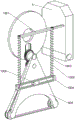
As a further preferred scheme, the second polishing mechanism comprises a rotary table, a sliding block, a second rotary shaft, a second large gear, a second triangular plate, a second transmission wheel, a second polishing belt and a second small gear, the rotary table is rotatably connected to the right side of the first rotary shaft, the rotary table is located on the right side of the first large gear, a sliding groove is formed in the bottom of the rotary table, scales are carved on two sides of the sliding groove, the sliding block is slidably mounted in the sliding groove, the sliding block is rotatably connected with the second rotary shaft, the second large gear is connected to the right side of the second rotary shaft, the second triangular plate is rotatably connected to the right side of the second rotary shaft, the second rotary shaft is rotatably connected to three corners of the second triangular plate, the second polishing belt is wound among the three second transmission wheels, the second small gear is connected to the second transmission wheel at the top corner of the second triangular plate, and the second small gear is meshed with the second large gear above the second transmission wheel.
As further preferred scheme, adjustment mechanism is connected with first lead screw including first lead screw and knob in the spout on the carousel bottom rotary type, and first lead screw one end inlays in the carousel, and the other end is connected with the knob, and the knob exposes on the outer edge of carousel, and sliding block threaded connection is on first lead screw.
As a further preferred scheme, the limiting mechanism comprises a sliding rod, guide rods, a first elastic part, a sliding frame and a fixed block, the sliding rod is connected to the sliding plate, the position of the sliding rod corresponds to that of a second triangular plate below the sliding rod, the two guide rods are slidably mounted on the sliding rod, one end of each guide rod is connected to the sliding frame, the first elastic part is arranged between the sliding rod and the sliding frame, the first elastic parts are all wound on the guide rods, the fixed block is connected to the second triangular plate, and the fixed block is slidably mounted in the sliding frame.
As further preferred scheme, fixed establishment is including the ring, the extrusion buckle, the fixed plate, round bar and second elastic component, the ring is installed along the carousel is outer, be equipped with the tang on the ring, the center department at the sliding plate front side is connected to the ring, the knob department rotary type on the carousel outer edge is connected with the extrusion buckle, bilateral symmetry is connected with the fixed plate on the extrusion buckle, the round bar is installed to equal slidingtype on the fixed plate, be equipped with the second elastic component between fixed plate and the extrusion buckle, the second elastic component is around on the round bar.
As a further preferred scheme, the device further comprises a second screw rod and a third screw rod, the second screw rod is rotatably connected in the bottom of the left mounting plate, the right mounting plate is in threaded connection with the second screw rod, a sliding plate on the base is rotatably connected with the third screw rod, and the bottom of the sliding plate is in threaded connection with the third screw rod.
As a further preferable scheme, the device further comprises a power mechanism, the power mechanism comprises four third conveying wheels, eight prisms, a third conveying wheel, a conveying belt and a protective shell, the number of the third conveying wheels is four, the mounting frames are symmetrically mounted on the left side and the right side of the base, the right mounting frame is located on the right side of the right mounting plate, the left mounting frame penetrates through the left mounting plate and is connected to the top end of the base, eight prisms are rotatably connected to the tops of the two mounting frames, the third conveying wheels are slidably mounted on the eight prisms, the third conveying wheel is connected to the first rotating shaft and corresponds to the third conveying wheel slidably mounted on the eight prisms, the third conveying wheel is connected to the left end of the eight prisms, the third conveying wheel is connected to the output shaft of the motor, the third conveying wheel at the left end of the eight prisms corresponds to the third conveying wheel on the output shaft of the motor, the conveying belts are wound between the third conveying wheels, and the protective shell is mounted at the position of the conveying belt wound between the third conveying wheel slidably mounted on the eight prisms and the third conveying wheel on the first rotating shaft.
Compared with the prior art, the invention has the following advantages:
1. according to the crankshaft main shaft journal and the crankshaft connecting rod journal polishing device, the first abrasive belt and the second abrasive belt are driven by the first rotating shaft through the power sources of the first abrasive belt and the second abrasive belt, so that the first abrasive belt and the second abrasive belt can simultaneously rotate, the main shaft journal and the connecting rod journal of the crankshaft can be simultaneously polished, and the effect that the main shaft journal and the connecting rod journal of the crankshaft do not need to be respectively polished is achieved.
2. According to the invention, the third transmission wheel is connected to the output shaft of the motor, and the transmission belts are wound among the third transmission wheels to drive the third transmission wheel on the first rotating shaft to rotate, so that the first abrasive belt and the second abrasive belt rotate, and the three-jaw chuck, the first abrasive belt and the second abrasive belt are in the same rotating period, so that the polishing precision of the crankshaft is improved.
Drawings
Fig. 1 is a schematic perspective view of the present invention.
Fig. 2 is a schematic perspective view of the components of the first grinding mechanism according to the present invention.
Figure 3 is a perspective view of a first component of a second grinding mechanism according to the present invention.
Figure 4 is a perspective view of a second component of a second grinding mechanism according to the present invention.
Fig. 5 is a schematic perspective view of the adjusting mechanism of the present invention.
Fig. 6 is a perspective view of the components of the adjusting mechanism of the present invention.
Fig. 7 is a schematic perspective view of a component of the limiting mechanism of the present invention.
Fig. 8 is a perspective view of a first component of the fixing mechanism of the present invention.
Fig. 9 is a perspective view of a second component of the fixing mechanism of the present invention.
Fig. 10 is a perspective view of the base and three-jaw chuck of the present invention.
Fig. 11 is a schematic perspective view of a first component of the power mechanism according to the present invention.
Fig. 12 is a perspective view of a second component of the power mechanism of the present invention.
Fig. 13 is a perspective view of a third component of the power mechanism of the present invention.
Wherein: 1-base, 2-mounting plate, 3-motor, 4-three-jaw chuck, 5-sliding plate, 6-connecting plate, 7-first grinding mechanism, 701-first rotating shaft, 702-first large gear, 703-first triangular plate, 704-first transmission wheel, 705-first grinding belt, 706-first small gear, 8-second grinding mechanism, 801-rotating disc, 802-sliding block, 803-second rotating shaft, 804-second large gear, 805-second triangular plate, 806-second transmission wheel, 807-second grinding wheel, 808-second small gear, 9-adjusting mechanism, 901-first lead screw, 902-knob, 10-limiting mechanism, 1001-sliding bar, 1002-guide bar, 1003-first elastic piece, 1004-sliding frame, 1005-fixing block, 11-fixing mechanism, 1101-circular ring, 1101-extrusion buckle, 1103-fixing plate, 1104-circular bar, 1402-second elastic piece, 1105-second elastic piece, 12-second lead screw, 13-third lead screw, 1401, 14-third lead screw, 14-protective housing, 14-prism-transmission rack, 1405-second prism transmission rack, 1405-second lead screw, and 1405-knob.
Detailed Description
The invention is further described below with reference to the figures and examples.
Example 1
The utility model provides an automobile crankshaft auxiliary polishing device, as shown in fig. 1-9, including base 1, mounting panel 2, motor 3, three-jaw chuck 4, sliding plate 5, connecting plate 6, first grinding mechanism 7, second grinding mechanism 8, adjustment mechanism 9, stop gear 10 and fixed establishment 11, mounting panel 2 is installed to the base 1 top left and right sides, mounting panel 2 slidable type on right side is installed on base 1, the equal rotary type in the inboard center department of mounting panel 2 is connected with three-jaw chuck 4, the outside center department of left side mounting panel 2 installs motor 3, motor 3 output shaft runs through mounting panel 2 and connects on three-jaw chuck 4, sliding plate 5 is slidably installed on base 1, sliding plate 5 is last to be connected with two connecting plates 6 at the interval, be provided with first grinding mechanism 7 that is used for the polish crankshaft main journal on connecting plate 6, still be provided with the second grinding mechanism 8 that is used for polish crankshaft connecting rod journal, be provided with the adjustment mechanism 9 that is used for adjusting second grinding mechanism 8 on the second grinding mechanism 8, be provided with the stop gear 10 that is used for restricting second grinding mechanism 8 on second grinding mechanism 8, still be provided with the fixed establishment 11 that is used for assisting adjustment mechanism 9.
As shown in fig. 1 and fig. 2, the first grinding mechanism 7 includes a first rotating shaft 701, a first large gear 702, a first triangular plate 703, a first transmission wheel 704, a first grinding belt 705 and a first small gear 706, the first rotating shaft 701 is rotatably connected to two connecting plates 6, the first large gear 702 is connected to the right side of the first rotating shaft 701, the first triangular plate 703 is rotatably connected to the first rotating shaft 701, the first triangular plate 703 is located on the left side of the first large gear 702, the first transmission wheels 704 are rotatably connected to three corners of the first triangular plate 703, the first grinding belt 705 is wound between the three first transmission wheels 704, the first small gear 706 is connected to the first transmission wheel 704 at the top corner of the first large gear 703, and the first small gear 706 is engaged with the first large gear 702 above.
As shown in fig. 1, 3 and 4, the second grinding mechanism 8 includes a rotary plate 801, a sliding block 802, a second rotating shaft 803, a second gearwheel 804, a second triangle 805, a second conveying wheel 806, a second grinding belt 807 and a second pinion 808, the rotary plate 801 is rotatably connected to the right side of the first rotating shaft 701, the rotary plate 801 is located on the right side of the first gearwheel 702, a sliding slot is formed at the bottom of the rotary plate 801, scales are carved on both sides of the sliding slot, the sliding block 802 is slidably mounted in the sliding slot, the second rotating shaft 803 is rotatably connected to the sliding block 802, the second gearwheel 804 is connected to the right side of the second rotating shaft 803, the second triangle 805 is located on the right side of the second gearwheel 804, the second rotating shaft 803 is rotatably connected to all three corners of the second triangle 805, the second grinding belt 807 is wound between the three second conveying wheels 806, the second conveying wheel 806 is connected to the second conveying wheel 806 at the top corner of the second triangle 805, and the second pinion 808 is engaged with the second gearwheel 804 above.
As shown in fig. 1, 5 and 6, the adjusting mechanism 9 includes a first lead screw 901 and a knob 902, the first lead screw 901 is rotatably connected in a chute on the bottom of the turntable 801, one end of the first lead screw 901 is embedded in the turntable 801, the other end of the first lead screw is connected with the knob 902, the knob 902 is exposed on the outer edge of the turntable 801, and the sliding block 802 is threadedly connected to the first lead screw 901.
As shown in fig. 1 and 7, the limiting mechanism 10 includes a sliding bar 1001, a guide bar 1002, a first elastic member 1003, a sliding frame 1004 and a fixed block 1005, the sliding bar 5 is connected with the sliding bar 1001, the sliding bar 1001 corresponds to the position of a second triangle 805 below, the sliding bar 1001 is slidably mounted with two guide bars 1002, one end of each guide bar 1002 is connected with the sliding frame 1004, the first elastic member 1003 is arranged between the sliding bar 1001 and the sliding frame 1004, the first elastic members 1003 are all wound on the guide bars 1002, the second triangle 805 is connected with the fixed block 1005, and the fixed block 1005 is slidably mounted in the sliding frame 1004. The first elastic member 1003 is a compression spring.
As shown in fig. 1, 8 and 9, the fixing mechanism 11 includes a ring 1101, a pressing buckle 1102, a fixing plate 1103, a round bar 1104 and a second elastic member 1105, the ring 1101 is installed on the outer edge of the rotation plate 801, a convex opening is formed on the ring 1101, the ring 1101 is connected to the center of the front side of the sliding plate 5, the pressing buckle 1102 is rotatably connected to a knob 902 on the outer edge of the rotation plate 801, the fixing plates 1103 are bilaterally and symmetrically connected to the pressing buckle 1102, the round bar 1104 is slidably installed on the fixing plate 1103, the second elastic member 1105 is arranged between the fixing plate 1103 and the pressing buckle 1102, and the second elastic member 1105 is wound around the round bar 1104. The second elastic member 1105 is a compression spring.
When the device needs to process and polish the automobile crankshaft, one end of the crankshaft is placed in the three-jaw chuck 4 on the left mounting plate 2, the other end of the crankshaft is placed in the three-jaw chuck 4 on the right mounting plate 2, the right mounting plate 2 is moved to be clamped and matched with the left three-jaw chuck 4 to fix the crankshaft, the sliding plate 5 is moved to ensure that the first abrasive belt 705 is over against the main journal of the crankshaft, the second abrasive belt 807 is over against the connecting rod journal of the crankshaft, after the position is moved, the position of the connecting rod journal of the first section of the crankshaft is recorded through scales on the turntable 801, then the first rotating shaft 701 is connected with a power source capable of rotating the first rotating shaft 701 and is started, the motor 3 is also started at the same time, the rotating periods of the first rotating shaft 701 are consistent, and when the first rotating shaft 701 rotates, the first big gear 702 connected with the first rotating shaft is driven to rotate, meanwhile, a first pinion 706 engaged with the first pinion is enabled to rotate, the first pinion 706 is connected to a first transmission wheel 704 and drives a first abrasive belt 705 to rotate and continuously abrade a main journal of a rotating crankshaft to enable a rough surface of the crankshaft to become smooth and flat, as the turntable 801 is connected to a first rotating shaft 701, the turntable 801 rotates along with the first pinion, meanwhile, the second rotating shaft 803 rotates a second rotating shaft 803, the second rotating shaft 803 rotates a second gearwheel 804 above the second rotating shaft to drive a second pinion 808 engaged with the second gearwheel 804 to rotate, the second pinion 808 drives a second transmission wheel 806 to rotate and enable a second abrasive belt wound around the second transmission wheel 806 to rotate, the second abrasive belt 807 continuously abrades a connecting rod journal of the crankshaft, and the main journal and the connecting rod journal of the crankshaft are simultaneously ground and polished by the first abrasive belt 705 and the second abrasive belt 807, the working efficiency is greatly increased, after one section is ground, the position of the previously recorded connecting rod journal is used, the position of the connecting rod journal at the next section can be accurately adjusted to the position of the connecting rod journal at the next section by rotating the knob 902 at the outer edge of the rotary disc 801, the previous operation is repeated, and then the grinding and polishing are carried out, when the rotary disc 801 rotates, the second triangular plate 805 can swing up and down and left and right, when the rotating speed is too high, the swinging amplitude is increased, so that the polishing precision is influenced, when the second triangular plate 805 swings up and down and left and right, because the second triangular plate 805 is connected with the fixed block 1005, the fixed block 1005 is slidably arranged in the sliding frame 1004, so that the left and right swinging amplitude can only be limited in the sliding frame 1004, and the guide rod 1002 is connected on the sliding frame 1004, because the guide rod 1002 is wound with the first elastic part 1003, the guide rod can be buffered when swinging up and down, so that the swinging amplitude is reduced, the turntable 801 can swing when rotating, the knob 902 can be driven to rotate, and the polishing position of the guide rod can deviate.
Example 2
In addition to embodiment 1, as shown in fig. 10, the present invention further includes a second lead screw 12 and a third lead screw 13, the second lead screw 12 is rotatably connected in the bottom of the left side mounting plate 2, the right side mounting plate 2 is screwed to the second lead screw 12, the sliding plate 5 on the base 1 is rotatably connected to the third lead screw 13, and the bottom of the sliding plate 5 is screwed to the third lead screw 13.
As shown in fig. 1, 11, 12 and 13, the power mechanism 14 is further included, the power mechanism 14 includes four third transmission wheels 1403, transmission belts 1404 and a protective casing 1405, the number of the third transmission wheels 1403 is four, the left and right sides of the base 1 are symmetrically provided with the mounting frames 1401, the right mounting frame 1401 is located on the right side of the right mounting plate 2, the left mounting frame 1401 penetrates through the left mounting plate 2 and is connected to the top end of the base 1, the eight prisms 1402 are rotatably connected to the tops of the two mounting frames 1401, the third transmission wheels 1403 are slidably mounted on the eight prisms 1402, the third transmission wheels 1403 are connected to the first rotating shaft 701, the third transmission wheels 1403 on the first rotating shaft 701 correspond to the third transmission wheels 1403 slidably mounted on the eight prisms 1402, the third transmission wheels 1403 are connected to the left end of the eight prisms 1402, the third transmission wheels 1403 on the output shaft of the motor 3 are connected to the output shaft of the motor 3, the third transmission wheels 1403 on the left end of the eight prisms 1402 correspond to the third transmission wheels 1403 on the output shaft 3, the third transmission wheels 1403 on the first rotating shaft 701 correspond to the third transmission wheels 1403 on the eight prisms 1403, and the protective casing 1403 on the prism 1403 are slidably mounted on the eight prisms 1404.
When the left end and the right end of the crankshaft are fixed, the second screw rod 12 can be rotated, the mounting plate 2 on the right side is in threaded connection with the second screw rod 12, the mounting plate 2 on the right side can move during rotation, the positions of the crankshafts with different lengths can be adjusted conveniently, when the sliding plate 5 is moved to calibrate the positions of the first abrasive belt 705 and the second abrasive belt 807, the crankshafts can be moved by rotating the third screw rod 13, the positions can be adjusted by hands, the polishing precision of the crankshafts can be guaranteed, usually, fine adjustment cannot be carried out by hands, the crankshaft can reach a fine adjustment effect through the second screw rod 12 and the third screw rod 13, and the polishing precision is guaranteed.
Because the first rotating shaft 701 needs to be additionally connected with a power source, the use is extremely inconvenient, the third transmission wheel 1403 is connected to the output shaft of the motor 3, the transmission belt 1404 is wound between the third transmission wheels 1403, so that the eight prisms 1402 on the mounting frame 1401 can be driven to rotate, the eight prisms 1402 rotate to drive the third transmission wheel 1403 on the first rotating shaft 701 to rotate, the first rotating shaft 701 obtains one power source, and the power source is originated from the motor 3 on the mounting plate 2, so that the three-jaw chuck 4, the first abrasive belt 705 and the second abrasive belt 807 can be ensured to be in the same rotating period, and the polishing precision of the crankshaft is improved.
The above description is only for the specific embodiments of the present invention, but the scope of the present invention is not limited thereto, and any person skilled in the art can easily conceive of the changes or substitutions within the technical scope of the present invention, and all the changes or substitutions should be covered within the scope of the present invention. Therefore, the protection scope of the present invention shall be subject to the protection scope of the claims.
Claims (8)
1. The utility model provides an automobile crankshaft assists burnishing device which characterized in that: comprises a base (1), a mounting plate (2), a motor (3), a three-jaw chuck (4), a sliding plate (5), a connecting plate (6), a first grinding mechanism (7), a second grinding mechanism (8), an adjusting mechanism (9), a limiting mechanism (10) and a fixing mechanism (11), wherein the mounting plate (2) is mounted on the left side and the right side of the top end of the base (1), the mounting plate (2) on the right side is slidably mounted on the base (1), the three-jaw chuck (4) is rotatably connected to the center of the inner side of the mounting plate (2), the motor (3) is mounted on the center of the outer side of the mounting plate (2) on the left side, an output shaft of the motor (3) penetrates through the mounting plate (2) and is connected to the three-jaw chuck (4), the sliding plate (5) is slidably mounted on the base (1), the two connecting plates (6) are connected on the sliding plate (5) at intervals, the second grinding mechanism (7) for grinding crankshaft polishing main journal is arranged on the connecting plate (6), the second grinding mechanism (8) for polishing the crankshaft connecting rod journal is further arranged, the second grinding mechanism (8) is arranged on the second grinding mechanism (8) for adjusting mechanism (8) for limiting mechanism (8), a fixing mechanism (11) for assisting the adjusting mechanism (9) is also provided.
2. The auxiliary polishing device for the automobile crankshaft as claimed in claim 1, wherein: first grinding mechanism (7) is including first pivot (701), first gear wheel (702), first set square (703), first transfer wheel (704), first abrasive belt (705) and first pinion (706), first pivot (701) rotary type is connected on two connecting plates (6), first pivot (701) right side is connected with first gear wheel (702), first pivot (701) go up the rotary type and are connected with first set square (703), first set square (703) are located first gear wheel (702) left side, the equal rotary type in three edges and corners of first set square (703) is connected with first transfer wheel (704), around having first abrasive belt (705) between three first transfer wheel (704), be connected with first pinion (706) on first transfer wheel (704) of apex angle department on first set square (703), first pinion (706) and the first gear wheel (702) meshing of top.
3. The auxiliary polishing device for the automobile crankshaft as claimed in claim 2, wherein: the second grinding mechanism (8) comprises a rotary table (801), a sliding block (802), a second rotating shaft (803), a second large gear (804), a second triangular plate (805), a second conveying wheel (806), a second grinding belt (807) and a second pinion (808), the rotary table (801) is connected on the right side of the first rotating shaft (701) in a rotating mode, the rotary table (801) is located on the right side of the first large gear (702), a sliding groove is formed in the bottom of the rotary table (801), scales are carved on two sides of the sliding groove, the sliding block (802) is installed in the sliding groove in a sliding mode, the second rotating shaft (803) is connected on the sliding block (802) in a rotating mode, the second large gear (804) is connected on the right side of the second rotating shaft (803) in a rotating mode, the second triangular plate (805) is located on the right side of the second large gear (804), the second rotating shaft (803) is connected on three corners of the second triangular plate (805) in a rotating mode, the second rotating shaft (803) is wound around the second conveying wheel (806), the second grinding belt (805) is located on the top corner of the second large gear (806), and the second large gear (808), and the second rotating shaft (808) is meshed with the second pinion (808).
4. An auxiliary polishing device for an automobile crankshaft as claimed in claim 3, wherein: adjustment mechanism (9) is connected with first lead screw (901) including first lead screw (901) and knob (902) in the spout of carousel (801) bottom rotary type, and first lead screw (901) one end inlays in carousel (801), and the other end is connected with knob (902), and knob (902) expose on carousel (801) outer edge, and sliding block (802) threaded connection is on first lead screw (901).
5. An auxiliary polishing device for an automobile crankshaft according to claim 4, wherein: the limiting mechanism (10) comprises a sliding rod (1001), guide rods (1002), a first elastic part (1003), a sliding frame (1004) and a fixed block (1005), the sliding rod (1001) is connected to the sliding plate (5), the position of the sliding rod (1001) corresponds to that of a second triangular plate (805) below, the two guide rods (1002) are slidably mounted on the sliding rod (1001), one end of each guide rod (1002) is connected to the sliding frame (1004), the first elastic part (1003) is arranged between the sliding rod (1001) and the sliding frame (1004), the first elastic part (1003) is wound on the guide rods (1002), the second triangular plate (805) is connected with the fixed block (1005), and the fixed block (1005) is slidably mounted in the sliding frame (1004).
6. An auxiliary polishing device for an automobile crankshaft as claimed in claim 5, wherein: fixed establishment (11) is including ring (1101), extrusion buckle (1102), fixed plate (1103), pole (1104) and second elastic component (1105), ring (1101) are installed to carousel (801) outer edge, be equipped with the bead on ring (1101), the center department at sliding plate (5) front side is connected to ring (1101), knob (902) the rotary type on carousel (801) outer edge is located and is connected with extrusion buckle (1102), bilateral symmetry is connected with fixed plate (1103) on extrusion buckle (1102), pole (1104) are all installed to sliding type on fixed plate (1103), be equipped with second elastic component (1105) between fixed plate (1103) and extrusion buckle (1102), second elastic component (1105) are around on pole (1104).
7. The auxiliary polishing device for the automobile crankshaft as claimed in claim 6, wherein: the novel screw rod mechanism is characterized by further comprising a second screw rod (12) and a third screw rod (13), wherein the second screw rod (12) is rotatably connected into the bottom of the left mounting plate (2), the right mounting plate (2) is in threaded connection with the second screw rod (12), a sliding plate (5) on the base (1) is rotatably connected with the third screw rod (13), and the bottom of the sliding plate (5) is in threaded connection with the third screw rod (13).
8. An auxiliary polishing device for an automobile crankshaft as claimed in claim 7, wherein: the automatic conveying device is characterized by further comprising a power mechanism (14), wherein the power mechanism (14) comprises an installation frame (1401), eight prisms (1402), a third conveying wheel (1403), a conveying belt (1404) and a protective shell (1405), the installation frame (1401) is symmetrically installed on the left side and the right side of the base (1), the right installation frame (1401) is located on the right side of the right installation plate (2), the left installation frame (1401) penetrates through the left installation plate (2) and is connected to the top end of the base (1), the eight prisms (1402) are rotatably connected to the tops of the two installation frames (1401), the third conveying wheel (1403) is slidably installed on the eight prisms (1402), the third conveying wheel (1403) is connected to the first rotating shaft (701), a third transmission wheel (1403) on the first rotating shaft (701) corresponds to the third transmission wheel (1403) slidably mounted on the eight-prism (1402), the third transmission wheel (1403) is connected to the left end of the eight-prism (1402), the third transmission wheel (1403) is connected to an output shaft of the motor (3), the third transmission wheel (1403) on the left end of the eight-prism (1402) corresponds to the third transmission wheel (1403) on the output shaft of the motor (3), transmission belts (1404) are wound between the third transmission wheels (1403), and the transmission belts (1404) wound between the third transmission wheel (1403) on the first rotating shaft (701) and the third transmission wheel (1403) slidably mounted on the eight-prism (1402) ) Is provided with a protective shell (1405).
Priority Applications (1)
| Application Number | Priority Date | Filing Date | Title |
|---|---|---|---|
| CN202211523860.4A CN115837624A (en) | 2022-11-30 | 2022-11-30 | Auxiliary polishing device for automobile crankshaft |
Applications Claiming Priority (1)
| Application Number | Priority Date | Filing Date | Title |
|---|---|---|---|
| CN202211523860.4A CN115837624A (en) | 2022-11-30 | 2022-11-30 | Auxiliary polishing device for automobile crankshaft |
Publications (1)
| Publication Number | Publication Date |
|---|---|
| CN115837624A true CN115837624A (en) | 2023-03-24 |
Family
ID=85577518
Family Applications (1)
| Application Number | Title | Priority Date | Filing Date |
|---|---|---|---|
| CN202211523860.4A Withdrawn CN115837624A (en) | 2022-11-30 | 2022-11-30 | Auxiliary polishing device for automobile crankshaft |
Country Status (1)
| Country | Link |
|---|---|
| CN (1) | CN115837624A (en) |
Cited By (2)
| Publication number | Priority date | Publication date | Assignee | Title |
|---|---|---|---|---|
| CN117124156A (en) * | 2023-09-28 | 2023-11-28 | 辽宁科创重型内燃机曲轴有限公司 | Crankshaft grinding equipment with offset rotation center and crankshaft preparation process |
| CN117943960A (en) * | 2024-03-14 | 2024-04-30 | 江苏中祥汽车部件有限公司 | Crankshaft surface polishing machine |
-
2022
- 2022-11-30 CN CN202211523860.4A patent/CN115837624A/en not_active Withdrawn
Cited By (4)
| Publication number | Priority date | Publication date | Assignee | Title |
|---|---|---|---|---|
| CN117124156A (en) * | 2023-09-28 | 2023-11-28 | 辽宁科创重型内燃机曲轴有限公司 | Crankshaft grinding equipment with offset rotation center and crankshaft preparation process |
| CN117124156B (en) * | 2023-09-28 | 2024-02-09 | 辽宁科创重型内燃机曲轴有限公司 | Crankshaft grinding equipment with offset rotation center and crankshaft preparation process |
| CN117943960A (en) * | 2024-03-14 | 2024-04-30 | 江苏中祥汽车部件有限公司 | Crankshaft surface polishing machine |
| CN117943960B (en) * | 2024-03-14 | 2024-06-07 | 江苏中祥汽车部件有限公司 | Crankshaft surface polishing machine |
Similar Documents
| Publication | Publication Date | Title |
|---|---|---|
| CN110153837A (en) | A kind of stone ball grinding equipment | |
| CN112476181A (en) | Automatic polishing device for automobile square parts | |
| CN210678189U (en) | A router shell processing device | |
| CN212665669U (en) | Automobile parts grinding device convenient to angle regulation | |
| CN211992193U (en) | Multistation is stainless steel watchcase grinding device for synchronous processing | |
| CN216179140U (en) | Stainless steel processing burr equipment of polishing | |
| CN214603694U (en) | Burnishing device is used in valve processing | |
| CN221891670U (en) | Roller surface polishing device | |
| CN114952481A (en) | Hardware processing corner grinding machine tool | |
| CN211332615U (en) | Mirror roller burnishing machine | |
| CN220740624U (en) | Workpiece polishing treatment device | |
| CN222134436U (en) | A straight line edge grinding device for glass production | |
| CN217776634U (en) | Precise alloy shaft polishing device | |
| CN219853904U (en) | Polishing machine for processing crankshaft of diesel engine | |
| CN208231450U (en) | A kind of processing of stone grinding machine | |
| CN219359026U (en) | Circumferential polishing device for wooden disc body | |
| CN218051942U (en) | A grinding and polishing mechanical arm | |
| CN213702945U (en) | Automatic grinding device for shell welding | |
| CN214489998U (en) | A bulb grinding device for machine-building | |
| CN210997996U (en) | A multifunctional glass grinding device | |
| CN220561074U (en) | Bearing grinder fixing device | |
| CN220740469U (en) | Zinc oxide processing and polishing device | |
| CN223000254U (en) | Valve rod burring frock of polishing | |
| CN217143521U (en) | Watch shell buckle position polishing device | |
| CN214817775U (en) | Grinding wheel dressing device |
Legal Events
| Date | Code | Title | Description |
|---|---|---|---|
| PB01 | Publication | ||
| PB01 | Publication | ||
| SE01 | Entry into force of request for substantive examination | ||
| SE01 | Entry into force of request for substantive examination | ||
| WW01 | Invention patent application withdrawn after publication |
Application publication date: 20230324 |
|
| WW01 | Invention patent application withdrawn after publication |