CN115817889B - Automatic film pasting and breaking device of online winding packaging machine - Google Patents
Automatic film pasting and breaking device of online winding packaging machine Download PDFInfo
- Publication number
- CN115817889B CN115817889B CN202310133822.6A CN202310133822A CN115817889B CN 115817889 B CN115817889 B CN 115817889B CN 202310133822 A CN202310133822 A CN 202310133822A CN 115817889 B CN115817889 B CN 115817889B
- Authority
- CN
- China
- Prior art keywords
- fixedly connected
- plate
- plates
- motor
- lifting
- Prior art date
- Legal status (The legal status is an assumption and is not a legal conclusion. Google has not performed a legal analysis and makes no representation as to the accuracy of the status listed.)
- Active
Links
- 238000004804 winding Methods 0.000 title claims abstract description 43
- 238000004806 packaging method and process Methods 0.000 title claims abstract description 24
- 230000007246 mechanism Effects 0.000 claims abstract description 54
- 239000000463 material Substances 0.000 claims abstract description 39
- 238000005520 cutting process Methods 0.000 claims abstract description 20
- 238000003825 pressing Methods 0.000 claims abstract description 10
- 230000000087 stabilizing effect Effects 0.000 claims description 7
- 230000005540 biological transmission Effects 0.000 claims description 6
- 239000012528 membrane Substances 0.000 description 9
- 230000003028 elevating effect Effects 0.000 description 5
- 210000002489 tectorial membrane Anatomy 0.000 description 5
- 230000000694 effects Effects 0.000 description 3
- 238000010030 laminating Methods 0.000 description 3
- 238000005096 rolling process Methods 0.000 description 3
- 239000007888 film coating Substances 0.000 description 2
- 238000009501 film coating Methods 0.000 description 2
- 238000012856 packing Methods 0.000 description 2
- 230000009471 action Effects 0.000 description 1
- 230000009286 beneficial effect Effects 0.000 description 1
- 230000007547 defect Effects 0.000 description 1
- 238000005516 engineering process Methods 0.000 description 1
- 238000003475 lamination Methods 0.000 description 1
- 238000004519 manufacturing process Methods 0.000 description 1
- 238000000034 method Methods 0.000 description 1
- 238000012986 modification Methods 0.000 description 1
- 230000004048 modification Effects 0.000 description 1
- 230000008569 process Effects 0.000 description 1
- 239000002699 waste material Substances 0.000 description 1
Images
Landscapes
- Basic Packing Technique (AREA)
Abstract
The invention relates to the field of packaging equipment, in particular to an automatic film sticking and breaking device of an online winding packaging machine, which comprises a fixed seat, wherein the upper surface of the fixed seat is provided with a conveying mechanism, and the surface and the upper part of the conveying mechanism are respectively provided with a cutting clamping mechanism; the cutting and clamping mechanism comprises a contact plate with fixed positions, a blade fixedly arranged on the side surface of the contact plate and a pressing plate movably arranged above the contact plate obliquely through a telescopic mechanism; the invention can wind and cover films on materials, automatically cut off when reaching the end part, fix the end part of a film belt, prevent the film belt from falling off, and continuously wind and cover films on the next material, thereby greatly improving the efficiency and reducing the manpower.
Description
Technical Field
The invention relates to the field of packaging equipment, in particular to an automatic film sticking and breaking device of an online winding packaging machine.
Background
In the packing process, the film wrapping is carried out on the objects, which is common equipment in the production workshop, and in the packing film wrapping of the materials, manual assistance is required for cutting off the film strip and clamping the re-film of the next material, or the complex relatively independent mechanism is required for assisting realization.
In addition, the materials need to be pushed to the appointed station side to be coated, positioning and placing of the materials are difficult, and the problems of time and labor waste of workers are caused.
Disclosure of Invention
The invention aims to solve the defects in the background technology, and provides an automatic film sticking and breaking device of an online winding packaging machine.
In order to achieve the above purpose, the invention adopts the following technical scheme: the automatic film sticking and breaking device of the online winding packaging machine comprises a fixed seat, wherein the upper surface of the fixed seat is provided with a conveying mechanism, and the surface and the upper part of the conveying mechanism are respectively provided with a cutting and clamping mechanism;
the cutting and clamping mechanism comprises a contact plate with fixed positions, a blade fixedly arranged on the side surface of the contact plate and a pressing plate movably arranged above the contact plate obliquely through a telescopic mechanism;
the side of fixing base is provided with elevating system, elevating system's lift end is provided with the connecting plate, the below rotation of connecting plate is connected with the ring gear, the lower surface of ring gear is connected with the mechanism of rolling up the membrane, the mechanism of rolling up the membrane is rotated in the outside circle that cuts off clamping mechanism when the ring gear rotates.
Preferably, the conveying mechanism comprises a roller row rotatably mounted on the upper surface of the fixing seat, and the roller row is provided with an opening close to the cutting clamping mechanism.
Preferably, the cutting and clamping mechanism comprises a side vertical plate with fixed positions and an extension plate fixedly connected to the end part of the side vertical plate, and the end part of the extension plate is fixedly connected to the edge of the contact plate.
Preferably, the telescopic machanism includes the telescopic link of fixed connection at side riser tip, the telescopic link's telescopic link fixedly connected with slider, the outside slip cap of slider is equipped with the cover rail, the lower surface fixedly connected with clamp plate of cover rail, the chute has been seted up to the side surface of clamp plate, the inboard slip of chute is provided with the guide pillar, the tip fixedly connected with of guide pillar is connected with the book pole, the upper end fixed connection of connecting the book pole is at the tip of side riser.
Preferably, the lower end of the side vertical plate below is fixedly connected to the inner bottom surface of the fixing seat, the upper end of the side vertical plate above is fixedly connected with a side connection plate, and the side connection plate is fixedly connected to the upper surface of the lifting mechanism.
Preferably, the elevating system includes two curb plates, fixed connection at the roof of two curb plate upper ends, fixed connection at the bottom plate of two curb plate lower extreme, the upper surface fixed mounting of roof has first motor, rotate between roof and the bottom plate and install the lead screw, the upper end of lead screw and the output shaft fixed connection of first motor, the surface cover of lead screw is equipped with mutual screw thread complex screw thread board, the tip fixedly connected with lifter plate of screw thread board, the upper end of lifter plate and the lateral end fixed connection of connecting plate, the side fixed connection of bottom plate is at the surface of fixing base.
Preferably, one side of the lifting plate, which is close to the screw rod, is vertically and fixedly connected with a plurality of stabilizing plates, and two sides of the stabilizing plates and the threaded plates are respectively in sliding fit with the surfaces of the side plates.
Preferably, the lower surface of connecting plate is close to tip department fixedly connected with link, the lower surface fixedly connected with collar of link, the ring gear rotates the cover and establishes in the outside of collar, the lower surface fixed mounting of connecting plate has the second motor, the output shaft fixedly connected with drive gear of second motor, drive gear meshes with the ring gear mutually.
Preferably, the film winding mechanism comprises a vertical frame fixedly connected to the lower surface of the toothed ring, a third motor fixedly installed at the lower end of the vertical frame, and a connecting flange fixedly connected to an output shaft of the third motor, wherein the lower surface of the connecting flange is fixedly connected with the material roller through a connecting bolt.
Compared with the prior art, the invention has the following beneficial effects:
1. this device can twine the tectorial membrane to the material to automatic cutout when reaching the tip, fix the tip of membrane area simultaneously, prevent that it from dropping, with the winding tectorial membrane of consecutive going on next material, improved efficiency greatly, reduce the manpower.
2. The material propelling movement is to its upper and lower limit position respectively lean on the edge of contact plate, drive gear through the second motor and rotate, and then make the ring gear rotate, thereby make vertical frame rotate, roll up membrane surface film area and bind around the material, simultaneously, first motor rotates, make the lead screw rotate, and then make the screw plate shift up, and then make connecting plate, collar and ring gear shift up simultaneously, shift up promptly when carrying out the membrane area and bind around, wrap up the material with abundant, can reach the effect of quick tectorial membrane.
3. When winding to the top, when winding to the contact plate surface, the telescopic link is elongated for the clamp plate moves down, and the guide pillar slides along the inboard of chute, and then makes the clamp plate slant down move, with the membrane strip clamp, cooperates the effect of blade for the membrane strip is cut off, and the tip of simultaneous membrane strip is pressed from both sides between clamp plate and contact plate, prevents to drop, can automatic cutout and clamp when reaching the tip, raises the efficiency.
4. After the material is taken down, another material is arranged, then, the toothed ring is reversed, the material is wound from top to bottom by the laminating film, when the material reaches the lowest position, the contact film belt contacts the contact plate below, then the cutting and clamping steps are carried out, then, the next material is replaced, the laminating film winding from bottom to top is carried out, and the operation is carried out in a reciprocating manner, so that the device can rapidly laminate the film, continuously carry out the laminating film of the next material, the winding efficiency is greatly improved, and the manual work intensity is reduced.
Drawings
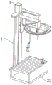
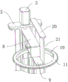
FIG. 1 is a schematic structural view of an automatic film sticking and breaking device of an on-line winding packaging machine;
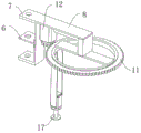
FIG. 2 is a schematic view of the tooth ring of an automatic film sticking and breaking device of an on-line winding packaging machine;
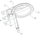
FIG. 3 is a schematic view of another view angle of the toothed ring of the automatic film sticking and breaking device of the on-line winding packaging machine;
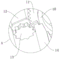
FIG. 4 is an enlarged view of the automatic film sticking and breaking device of the on-line winding packaging machine at the position A in FIG. 4;
FIG. 5 is a schematic view of a part of an automatic film sticking and breaking device of an on-line winding packaging machine;
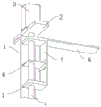
FIG. 6 is a schematic view of a lifting mechanism of an automatic film sticking and breaking device of an on-line winding packaging machine;
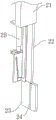
FIG. 7 is a schematic view of a contact plate of an automatic film sticking and breaking device of an on-line winding packaging machine;
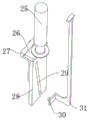
FIG. 8 is a schematic view of a platen of an automatic film sticking and breaking device for an on-line winding packaging machine according to the present invention;
FIG. 9 is a schematic view of the lower end of a vertical frame of an automatic film sticking and breaking device of an on-line winding packaging machine;
FIG. 10 is a schematic view of a fixing seat of an automatic film sticking and breaking device of an on-line winding packaging machine;
FIG. 11 is a schematic illustration of an automatic film sticking and breaking device of an on-line winding packaging machine during film lamination;
fig. 12 is a top view of an automatic film sticking and breaking device for an on-line winding packaging machine.
1. A side plate; 2. a top plate; 3. a first motor; 4. a screw rod; 5. a lifting plate; 6. a thread plate; 7. a stabilizing plate; 8. a connecting plate; 9. a connecting frame; 10. a mounting ring; 11. a toothed ring; 12. a second motor; 13. a transmission gear; 14. a vertical frame; 15. a third motor; 16. a connecting flange; 17. a material roller; 18. a connecting bolt; 19. film rolling; 20. a lateral connecting plate; 21. side risers; 22. an extension plate; 23. a contact plate; 24. a blade; 25. a telescopic rod; 26. a slide block; 27. a sleeve rail; 28. a pressing plate; 29. a chute; 30. a guide post; 31. connecting a folding rod; 32. a bottom plate; 33. a fixing seat; 34. a roller row; 35. a material; 36. a film-covered surface; 37. a portion to be cut; 38. and a clamping part.
Detailed Description
The following description is presented to enable one of ordinary skill in the art to make and use the invention. The preferred embodiments in the following description are by way of example only and other obvious variations will occur to those skilled in the art.
The automatic film sticking and breaking device of the online winding packaging machine as shown in fig. 1-12 comprises a fixed seat 33, wherein a conveying mechanism is arranged on the upper surface of the fixed seat 33, and a cutting and clamping mechanism is respectively arranged on the surface and above the conveying mechanism;
the cutting and clamping mechanism comprises a contact plate 23 with a fixed position, a blade 24 fixedly arranged on the side surface of the contact plate 23, and a pressing plate 28 movably arranged above the contact plate 23 through a telescopic mechanism;
the side of fixing base 33 is provided with elevating system, elevating system's lift end is provided with connecting plate 8, and the below rotation of connecting plate 8 is connected with ring gear 11, and ring gear 11's lower surface is connected with a film winding mechanism, and film winding mechanism rotates in cutting off clamping mechanism's outside circle when ring gear 11 rotates.
This device can twine the tectorial membrane to material 35 to automatic cutout when reaching the tip, fix the tip of membrane area simultaneously, prevent that it from dropping, with consecutive winding tectorial membrane of going on next material 35, improved efficiency greatly, reduce the manpower.
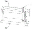
As shown in fig. 10, the conveying mechanism includes a roller row 34 rotatably mounted on the upper surface of the fixed base 33, and the roller row 34 is provided with an opening near the cutting clamping mechanism, the opening ensuring that the cutting clamping mechanism is provided with a space.
As shown in fig. 7 and 8, the cutting and clamping mechanism includes a fixed-position side riser 21 and an extension plate 22 fixedly connected to an end of the side riser 21, and an end of the extension plate 22 is fixedly connected to an edge of the contact plate 23. The telescopic machanism includes telescopic link 25 of fixed connection at side riser 21 tip, telescopic link 25 selects the cylinder, control flexible reaction is fast, telescopic link 25's telescopic link fixedly connected with slider 26, slider 26's outside slip cover is equipped with the cover rail 27, the lower fixed surface of cover rail 27 is connected with clamp plate 28, chute 29 has been seted up to clamp plate 28's side surface, chute 29's inboard slip is provided with guide pillar 30, guide pillar 30's tip fixedly connected with connects roll over lever 31, connect roll over lever 31's upper end fixed connection at side riser 21's tip, the cooperation of cover rail 27 and slider 26, make clamp plate 28 translation relatively, telescopic link 25 flexible makes clamp plate 28 move down simultaneously, the combination of two application directions, make clamp plate 28 slant move down.
As shown in fig. 5 and 10, the lower end of the lower side riser 21 is fixedly connected to the inner bottom surface of the fixed seat 33, the upper end of the upper side riser 21 is fixedly connected to the side plate 20, and the side plate 20 is fixedly connected to the upper surface of the lifting mechanism.
As shown in fig. 6, the lifting mechanism comprises two side plates 1, a top plate 2 fixedly connected to the upper ends of the two side plates 1, and a bottom plate 32 fixedly connected to the lower ends of the two side plates 1, a first motor 3 is fixedly mounted on the upper surface of the top plate 2, a screw rod 4 is rotatably mounted between the top plate 2 and the bottom plate 32, the upper end of the screw rod 4 is fixedly connected with an output shaft of the first motor 3, a threaded plate 6 in threaded fit with each other is sleeved on the outer surface of the screw rod 4, a lifting plate 5 is fixedly connected to the end part of the threaded plate 6, the upper end of the lifting plate 5 is fixedly connected with the side end of the connecting plate 8, and the side edge of the bottom plate 32 is fixedly connected to the outer surface of the fixing seat 33.
One side of the lifting plate 5, which is close to the screw rod 4, is vertically and fixedly connected with a plurality of stabilizing plates 7, and two sides of the stabilizing plates 7 and the threaded plates 6 are respectively in sliding fit with the surfaces of the side plates 1 so as to improve the stability of the lifting plate 5 when moving up and down.
As shown in fig. 2, 3, 4 and 5, a connecting frame 9 is fixedly connected to the lower surface of the connecting plate 8 near the end, a mounting ring 10 is fixedly connected to the lower surface of the connecting frame 9, a toothed ring 11 is rotatably sleeved on the outer side of the mounting ring 10, a second motor 12 is fixedly mounted on the lower surface of the connecting plate 8, a transmission gear 13 is fixedly connected to an output shaft of the second motor 12, and the transmission gear 13 is meshed with the toothed ring 11.
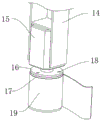
As shown in fig. 3 and 9, the film winding mechanism comprises a vertical frame 14 fixedly connected to the lower surface of the toothed ring 11, a third motor 15 fixedly installed at the lower end of the vertical frame 14, and a connecting flange 16 fixedly connected to an output shaft of the third motor 15, wherein the lower surface of the connecting flange 16 is fixedly connected with a material roller 17 through a connecting bolt 18 so as to facilitate the disassembly and replacement of the material roller 17, and when the film winding mechanism is used, a film winding 19 is arranged on the surface of the material roller 17, and the material roller 17 can be integrally replaced when the film winding mechanism runs out, or the film winding belt is wound again by means of the operation of the third motor 15 to form the film winding 19.
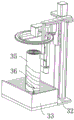
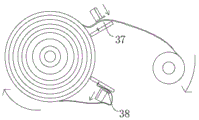
During winding and packaging, a worker pushes the material 35 to the positions of the upper edge and the lower edge of the material 35 to lean against the edge of the contact plate 23 respectively, the second motor 12 drives the transmission gear 13 to rotate, so that the toothed ring 11 rotates, the vertical frame 14 rotates, the surface film strip of the film winding 19 bundles the material 35, meanwhile, the first motor 3 rotates, the screw rod 4 rotates, the thread plate 6 moves upwards, the connecting plate 8, the mounting ring 10 and the toothed ring 11 move upwards at the same time, namely, the film strip bundles the material 35 and the material are fully wrapped, the effect of quick film coating can be achieved, and as shown in fig. 11, the surface of the material 35 is wound to form a film coating surface 36; as shown in fig. 12, when the film is wound to the uppermost, a portion to be cut 37 is formed when the film is wound on the surface of the contact plate 23, the telescopic rod 25 stretches to enable the pressing plate 28 to move downwards, the guide post 30 slides along the inner side of the chute 29 to enable the pressing plate 28 to move downwards obliquely to clamp the film strip, the film strip is cut off under the action of the blade 24, and meanwhile, the end part of the film strip is clamped between the pressing plate 28 and the contact plate 23 to prevent falling, at the moment, the clamping part 38 at the lower part is positioned, the telescopic rod 25 contracts to release the film strip, so that the material 35 can be detached, and the film strip can be automatically cut off and clamped when the end part is reached, thereby improving the efficiency; after the material 35 is taken down, another material is arranged, then, the toothed ring 11 is reversed, the material 35 is wound by covering films from top to bottom, when the material reaches the lowest position, the contact film belt contacts the contact plate 23 below, then the cutting and clamping steps are carried out, then, the next material 35 is replaced, and covering film winding from bottom to top is carried out, and the operation is carried out in a reciprocating manner.
The foregoing has shown and described the basic principles, principal features and advantages of the invention. It will be understood by those skilled in the art that the present invention is not limited to the embodiments described above, and that the above embodiments and descriptions are merely illustrative of the principles of the present invention, and various changes and modifications may be made therein without departing from the spirit and scope of the invention, which is defined by the appended claims. The scope of the invention is defined by the appended claims and equivalents thereof.
Claims (3)
1. The utility model provides an automatic pad pasting film breaking device of online winding packagine machine, includes fixing base (33), its characterized in that: the upper surface of the fixed seat (33) is provided with a conveying mechanism, and the surface and the upper part of the conveying mechanism are respectively provided with a cutting clamping mechanism;
the cutting and clamping mechanism comprises a contact plate (23) with a fixed position, a blade (24) fixedly arranged on the side surface of the contact plate (23), and a pressing plate (28) movably arranged above the contact plate (23) in an inclined manner through a telescopic mechanism;
the side of the fixed seat (33) is provided with a lifting mechanism, the lifting end of the lifting mechanism is provided with a connecting plate (8), a toothed ring (11) is rotationally connected below the connecting plate (8), the lower surface of the toothed ring (11) is connected with a film winding mechanism, and the film winding mechanism rotates around the outer side of the cutting clamping mechanism when the toothed ring (11) rotates;
the conveying mechanism comprises a roller row (34) rotatably arranged on the upper surface of the fixed seat (33), and the roller row (34) is provided with an opening close to the cutting clamping mechanism;
the cutting and clamping mechanism comprises a side vertical plate (21) with a fixed position and an extension plate (22) fixedly connected to the end part of the side vertical plate (21), and the end part of the extension plate (22) is fixedly connected to the edge of the contact plate (23);
the telescopic mechanism comprises a telescopic rod (25) fixedly connected to the end part of a side vertical plate (21), a sliding block (26) is fixedly connected to the telescopic end of the telescopic rod (25), a sleeve rail (27) is sleeved on the outer side of the sliding block (26) in a sliding mode, a pressing plate (28) is fixedly connected to the lower surface of the sleeve rail (27), a chute (29) is formed in the side surface of the pressing plate (28), a guide pillar (30) is arranged on the inner side of the chute (29) in a sliding mode, a connecting folding rod (31) is fixedly connected to the end part of the guide pillar (30), and the upper end of the connecting folding rod (31) is fixedly connected to the end part of the side vertical plate (21);
the lower end of the side vertical plate (21) below is fixedly connected to the inner bottom surface of the fixed seat (33), the upper end of the side vertical plate (21) above is fixedly connected with a side connection plate (20), and the side connection plate (20) is fixedly connected to the upper surface of the lifting mechanism;
the lower surface of the connecting plate (8) is fixedly connected with a connecting frame (9) near the end part, the lower surface of the connecting frame (9) is fixedly connected with a mounting ring (10), the toothed ring (11) is rotationally sleeved on the outer side of the mounting ring (10), the lower surface of the connecting plate (8) is fixedly provided with a second motor (12), the output shaft of the second motor (12) is fixedly connected with a transmission gear (13), and the transmission gear (13) is meshed with the toothed ring (11);
the film winding mechanism comprises a vertical frame (14) fixedly connected to the lower surface of the toothed ring (11), a third motor (15) fixedly installed at the lower end of the vertical frame (14), and a connecting flange (16) fixedly connected to an output shaft of the third motor (15), wherein the lower surface of the connecting flange (16) is fixedly connected with a material roller (17) through a connecting bolt (18).
2. The automatic film sticking and breaking device of an online winding packaging machine according to claim 1, wherein: the lifting mechanism comprises two side plates (1), a top plate (2) fixedly connected to the upper ends of the two side plates (1), and a bottom plate (32) fixedly connected to the lower ends of the two side plates (1), wherein a first motor (3) is fixedly arranged on the upper surface of the top plate (2), a screw rod (4) is rotatably arranged between the top plate (2) and the bottom plate (32), the upper end of the screw rod (4) is fixedly connected with an output shaft of the first motor (3), threaded plates (6) in threaded fit with each other are sleeved on the outer surfaces of the screw rod (4), lifting plates (5) are fixedly connected to the end parts of the threaded plates (6), the upper ends of the lifting plates (5) are fixedly connected with the side ends of the connecting plates (8), and the side edges of the bottom plate (32) are fixedly connected to the outer surfaces of fixing seats (33).
3. The automatic film sticking and breaking device of an online winding packaging machine according to claim 2, wherein: one side of the lifting plate (5) close to the screw rod (4) is vertically and fixedly connected with a plurality of stabilizing plates (7), and two sides of the stabilizing plates (7) and the threaded plates (6) are respectively in sliding fit with the surfaces of the side plates (1).
Priority Applications (1)
| Application Number | Priority Date | Filing Date | Title |
|---|---|---|---|
| CN202310133822.6A CN115817889B (en) | 2023-02-20 | 2023-02-20 | Automatic film pasting and breaking device of online winding packaging machine |
Applications Claiming Priority (1)
| Application Number | Priority Date | Filing Date | Title |
|---|---|---|---|
| CN202310133822.6A CN115817889B (en) | 2023-02-20 | 2023-02-20 | Automatic film pasting and breaking device of online winding packaging machine |
Publications (2)
| Publication Number | Publication Date |
|---|---|
| CN115817889A CN115817889A (en) | 2023-03-21 |
| CN115817889B true CN115817889B (en) | 2023-05-26 |
Family
ID=85521865
Family Applications (1)
| Application Number | Title | Priority Date | Filing Date |
|---|---|---|---|
| CN202310133822.6A Active CN115817889B (en) | 2023-02-20 | 2023-02-20 | Automatic film pasting and breaking device of online winding packaging machine |
Country Status (1)
| Country | Link |
|---|---|
| CN (1) | CN115817889B (en) |
Families Citing this family (5)
| Publication number | Priority date | Publication date | Assignee | Title |
|---|---|---|---|---|
| CN116573200B (en) * | 2023-07-10 | 2023-09-15 | 魏县垚顺新型节能建材有限公司 | Regenerated brick blank packing apparatus |
| CN117002782B (en) * | 2023-10-07 | 2023-12-15 | 江苏攀森智能科技有限公司 | Finished motor shell laminating and packaging device and packaging method thereof |
| CN117342054B (en) * | 2023-12-06 | 2024-04-09 | 湖南亿铠达新材料科技有限公司 | Sandwich composite board packaging equipment |
| CN119409002B (en) * | 2025-01-09 | 2025-04-11 | 山东盛合纸塑包装有限公司 | A rewinding machine for baking paper processing |
| CN119660086B (en) * | 2025-02-24 | 2025-05-30 | 江苏苏青水处理工程集团有限公司 | Be used for ion exchange resin to leave membrane heat shrink packagine machine |
Family Cites Families (10)
| Publication number | Priority date | Publication date | Assignee | Title |
|---|---|---|---|---|
| FI115395B (en) * | 2002-09-25 | 2005-04-29 | Haloila M Oy Ab | Winding machine and method for wrapping a wrapping film around an object |
| FI125041B (en) * | 2003-04-22 | 2015-05-15 | Signode Internat Ip Holdings Llc | Wrapping machine and method of wrapping a plastic wrap web around a product |
| DE202004001012U1 (en) * | 2004-01-23 | 2004-06-09 | Scheich, Dieter | Packaging film winding machine for winding film around a palette or similar has an improved mechanism for attachment, spreading and separation of winding film |
| CN206456592U (en) * | 2016-11-01 | 2017-09-01 | 厦门奥泰科机器人系统有限公司 | Portable film packing press people |
| CN208931717U (en) * | 2018-09-06 | 2019-06-04 | 广东鼎湖山泉有限公司 | A kind of automatic cantilever type winding-packing machine |
| CN210503318U (en) * | 2019-08-27 | 2020-05-12 | 苏州市旭锠达智能科技有限公司 | Gantry type cantilever top-covering winding machine |
| CN214524553U (en) * | 2021-02-04 | 2021-10-29 | 青岛梵荣达科技有限公司 | Covering machine |
| CN113460350A (en) * | 2021-07-13 | 2021-10-01 | 湖州清优包装材料有限公司 | Winding type intelligent packaging machine |
| CN113665868A (en) * | 2021-08-30 | 2021-11-19 | 许磊 | Automatic change winding packagine machine |
| CN217348340U (en) * | 2022-04-24 | 2022-09-02 | 青岛欣欣向荣智能设备有限公司 | Winding machine |
-
2023
- 2023-02-20 CN CN202310133822.6A patent/CN115817889B/en active Active
Also Published As
| Publication number | Publication date |
|---|---|
| CN115817889A (en) | 2023-03-21 |
Similar Documents
| Publication | Publication Date | Title |
|---|---|---|
| CN115817889A (en) | Automatic film sticking and breaking device of online winding packaging machine | |
| CN108455356B (en) | Portable automatic adhesive tape winding device | |
| CN104773564B (en) | A large roll material automatic edge banding tape system | |
| CN106079504A (en) | The automatic cloth-wrapping machine of wire loop | |
| CN105775199B (en) | One kind gripping feeding type section bar packaging facilities | |
| CN103000364A (en) | Automatic coil winder | |
| CN110902023A (en) | Automatic laminating and plastic packaging device and method for drying rack | |
| CN217406363U (en) | Sectional stator winding machine | |
| CN103737168B (en) | A filament welding machine | |
| CN115520454A (en) | Automatic packaging device and method for steel coil antirust paper | |
| CN110127119B (en) | Film packaging device | |
| CN206370467U (en) | Battery end twines glue machine | |
| CN112224486A (en) | Automatic packaging device and packaging method for welding wire spool | |
| CN217624264U (en) | Winding and top covering integrated machine | |
| CN204607179U (en) | A kind of large-scale coiled strip seals limit tape system automatically | |
| CN211644038U (en) | Automatic adhesive tape pasting equipment | |
| CN117002063A (en) | Automatic wrapping machine for double-winding-head bead rings | |
| CN116281321B (en) | Auxiliary production equipment for steel-plastic composite belt | |
| CN204278115U (en) | A kind of V-shaped rubber belt line base covers glue cutter sweep | |
| CN204323735U (en) | An automatic packaging machine | |
| CN202977161U (en) | Automatic coil winder | |
| CN114955670B (en) | A tension device for cigarette aluminum foil rewinding machine | |
| CN210708246U (en) | Novel looping, winding and film-coating integrated machine | |
| CN117884311A (en) | Glue spraying and paper pasting device for mosaic processing | |
| CN205651656U (en) | What V took infantees machine leads cloth structure |
Legal Events
| Date | Code | Title | Description |
|---|---|---|---|
| PB01 | Publication | ||
| PB01 | Publication | ||
| SE01 | Entry into force of request for substantive examination | ||
| SE01 | Entry into force of request for substantive examination | ||
| GR01 | Patent grant | ||
| GR01 | Patent grant |