CN115808536A - A fully automatic dry fluorescent immunoassay analyzer - Google Patents

A fully automatic dry fluorescent immunoassay analyzer Download PDF

Info

Publication number
CN115808536A
CN115808536A CN202211564527.8A CN202211564527A CN115808536A CN 115808536 A CN115808536 A CN 115808536A CN 202211564527 A CN202211564527 A CN 202211564527A CN 115808536 A CN115808536 A CN 115808536A
Authority
CN
China
Prior art keywords
module
driving mechanism
sample
transmission assembly
plate
Prior art date
Legal status (The legal status is an assumption and is not a legal conclusion. Google has not performed a legal analysis and makes no representation as to the accuracy of the status listed.)
Withdrawn
Application number
CN202211564527.8A
Other languages
Chinese (zh)
Inventor
唐金鑫
隆坤
李蒙蒙
邓志军
王群
何婷
胡清海
林�源
吴茜
Current Assignee (The listed assignees may be inaccurate. Google has not performed a legal analysis and makes no representation or warranty as to the accuracy of the list.)
Sichuan Xinjian Kangcheng Biological Co ltd
Original Assignee
Sichuan Xinjian Kangcheng Biological Co ltd
Priority date (The priority date is an assumption and is not a legal conclusion. Google has not performed a legal analysis and makes no representation as to the accuracy of the date listed.)
Filing date
Publication date
Application filed by Sichuan Xinjian Kangcheng Biological Co ltd filed Critical Sichuan Xinjian Kangcheng Biological Co ltd
Priority to CN202211564527.8A priority Critical patent/CN115808536A/en
Publication of CN115808536A publication Critical patent/CN115808536A/en
Withdrawn legal-status Critical Current

Links

Images

Landscapes

  • Automatic Analysis And Handling Materials Therefor (AREA)

Abstract

The invention discloses a full-automatic dry type fluorescence immunoassay analyzer, wherein a base is provided with a sample module, a reagent card box module, a transportation module, a shaking and cap pulling module, an incubation module, a control module, a sample adding module and a suction head box module, wherein the transportation module can hook reagent strips in the reagent card box module; the shaking cap pulling module can turn over the test tube in the sample module and pull and cover the test tube cap; the incubation module can incubate and collect light for the reagent strip; the application of sample module can absorb the sample and carry out the application of sample. The invention realizes the automatic in-and-out of the sample and the reading of the sample information by utilizing the sample module, thereby ensuring that the quick detection and reaction of the product have higher controllability, greatly improving the detection sensitivity and precision, reducing the labor intensity of workers, realizing the lighting modular design and ensuring the whole machine integration to be more quick and flexible.

Description

一种全自动干式荧光免疫分析仪A fully automatic dry fluorescence immunoassay analyzer

技术领域technical field

本发明涉及干式荧光免疫分析技术领域,具体是一种全自动干式荧光免疫分析仪。The invention relates to the technical field of dry fluorescent immunoassay, in particular to a fully automatic dry fluorescent immune analyzer.

背景技术Background technique

早期免疫产品为定性产品,免疫项目为研究对象,采用胶体金的方式。胶体金的产品为这个阶段的明星产品。以抗原抗体的结合原理,理论上可以标记几乎所有的蛋白分子,缺点是灵敏度低,精确度低,只能判断阴性和阳性;技术提升之后采用彩色微球标记,彩色微球标记与胶体金相比,灵敏度相比之前有所提高,检测结果可重复性强,可是灵敏度有限;随着技术的发展,荧光微球标记技术得到应用,荧光微球标记发光强而稳定,有较高的生物相容性且基本不受外界环境变化的影响,可以实现定量检测,但对产品工艺要求较高,难度提升。The early immune products were qualitative products, and the immune project was the research object, using colloidal gold. Colloidal gold products are the star products at this stage. Based on the combination principle of antigen and antibody, almost all protein molecules can be labeled theoretically. The disadvantage is that the sensitivity is low, the accuracy is low, and only negative and positive can be judged; after the technology is improved, colored microspheres are used for labeling. Compared with the previous ones, the sensitivity has been improved, and the test results are highly reproducible, but the sensitivity is limited; with the development of technology, the fluorescent microsphere labeling technology has been applied, and the fluorescent microsphere labeling has strong and stable luminescence, and has a high biophase Capacitive and basically not affected by changes in the external environment, quantitative detection can be achieved, but the requirements for product technology are high and the difficulty is increased.

而荧光免疫技术(fluorescenceImmuno technique)又称荧光抗体技术,是标记免疫技术中发展最早的一种,它是在免疫学、生物化学和显微镜技术的基础上建立起来的一项技术,干式免疫荧光分析仪:滴加在膜一端的样品溶液受膜的毛细管作用(基于层析作用的横流(lateral flow))向另一端移动,移动过程中被分析物与固定在膜上某一区域的受体(抗原或者抗体)结合而被固相化,无关物质则越过该区域而被分离,然后通过标记物检测(定性、半定量和定量)来判定试验结果,荧光免疫分析仪主要适应于各类医疗机构进行血液生物化学分析和检验,如激素类、感染类临床项目的检验。Fluorescence Immunotechnique (fluorescenceImmuno technique), also known as fluorescent antibody technology, is one of the earliest developments in labeling immunization techniques. It is a technology established on the basis of immunology, biochemistry and microscopy techniques. Dry immunofluorescence Analyzer: The sample solution dripped at one end of the membrane is moved to the other end by the capillary action of the membrane (lateral flow based on chromatography), during which the analyte and the receptor fixed on a certain area of the membrane (Antigen or antibody) is combined and solidified, and irrelevant substances are separated across the region, and then the test results are determined by marker detection (qualitative, semi-quantitative and quantitative). Fluorescence immunoassay analyzers are mainly suitable for various medical treatments The institution conducts blood biochemical analysis and testing, such as testing of hormones and infection clinical items.

现有的荧光免疫分析仪需要大量繁琐的人工步骤进行辅助检测,检测灵敏度和精密度较低。Existing fluorescent immunoassay analyzers require a large number of cumbersome manual steps for auxiliary detection, and the detection sensitivity and precision are low.

发明内容Contents of the invention

本发明的目的在于克服上述背景技术中提出的问题,提供了一种全自动干式荧光免疫分析仪,该分析仪使产品快速检测和反应更具有可控性,检测灵敏度和精密度也有较大提升,也减少人工步骤。The purpose of the present invention is to overcome the problems raised in the above-mentioned background technology and provide a fully automatic dry-type fluorescent immunoassay analyzer, which makes the rapid detection and reaction of products more controllable, and the detection sensitivity and precision are also greater. Lifting, also reducing manual steps.

本发明的目的主要通过以下技术方案实现:The purpose of the present invention is mainly achieved through the following technical solutions:

一种全自动干式荧光免疫分析仪,包括底座,所述底座上设置有样本模块、试剂卡盒模块、运输模块、摇匀拔帽模块、孵育模块、控制模块、加样模块和吸头盒模块,其中样本模块、运输模块、摇匀拔帽模块、孵育模块以及加样模块均与控制模块连接;所述运输模块能够勾取试剂卡盒模块中的试剂条;所述摇匀拔帽模块能够对样本模块中的试管进行翻转以及拔、盖试管帽;所述孵育模块能够对试剂条进行孵育和采光;所述加样模块能够吸取样本进行加样。A fully automatic dry fluorescent immunoassay analyzer, comprising a base, on which a sample module, a reagent cartridge module, a transport module, a shaker module, a cap removal module, an incubation module, a control module, a sampling module and a tip box are arranged. module, wherein the sample module, the transport module, the shaking module and the cap removal module, the incubation module and the sample loading module are all connected to the control module; the transport module can hook the reagent strips in the reagent cartridge module; The test tube in the sample module can be turned over, and the cap of the test tube can be removed and covered; the incubation module can incubate and light the reagent strip; the sample adding module can draw a sample and add a sample.

近年来,由于人体因环境等因素的影响,感染性疾病的新发,突发不断威胁人类健康,非典型肺炎、中东呼吸综合征、流感、埃博拉、寨卡病毒、黄热病、裂谷热等传染性疾病的传播,成为全球公共卫生问题。随着城市化的发展、全球贸易往来的增加,环境改变加剧自然疫源性传染病的传播风险,感染性疾病的预防控制刻不容缓。因此,开展传染病的即时快速检测,对于感染性疾病的防控工作具有重大意义。同时对人体血液样本进行快速检测,可有效、快速的检测出人体已经病发或潜在的疾病,作为有效治疗和前期预防病症同样具有重大意义。In recent years, due to the impact of the human body due to factors such as the environment, the emergence of new infectious diseases has continuously threatened human health, such as atypical pneumonia, Middle East respiratory syndrome, influenza, Ebola, Zika virus, yellow fever, crack The spread of infectious diseases such as valley fever has become a global public health problem. With the development of urbanization and the increase of global trade, environmental changes have increased the risk of transmission of infectious diseases in natural foci, and the prevention and control of infectious diseases is urgent. Therefore, the instant and rapid detection of infectious diseases is of great significance for the prevention and control of infectious diseases. At the same time, the rapid detection of human blood samples can effectively and quickly detect the onset or potential diseases of the human body, which is also of great significance as an effective treatment and early prevention of diseases.

POCT产品具有操作简便、便携、智能化等优点,近年来作为体外诊断技术发展迅速,被应用在多个学科的检测项目中。它的快速获取检测结果,方便病人,减少病人确诊的时间。同时POCT产品有连续使用监控病情的作用,比如心脏病患者,可以通过间隔时间的检测迅速了解并控制病情。POCT所应用的技术原理从传统的干化学技术、免疫层析技术与光学信息,数据分析技术等结合。采用生物医学技术、层析技术通过对色谱、光谱、生物传感器信息进行分析处理,应用于免疫和快速检测,实现多通道和自动化检测,提高其现场适用性,呈现出自动化和简单化的优势。POCT products have the advantages of easy operation, portability, and intelligence. In recent years, POCT has developed rapidly as an in vitro diagnostic technology and has been used in testing items in multiple disciplines. Its quick access to test results is convenient for patients and reduces the time for patients to be diagnosed. At the same time, POCT products can be used continuously to monitor the condition. For example, heart disease patients can quickly understand and control the condition through the detection of interval time. The technical principle applied by POCT combines traditional dry chemical technology, immunochromatography technology with optical information and data analysis technology. Using biomedical technology and chromatography technology to analyze and process chromatography, spectrum, and biosensor information, apply it to immunity and rapid detection, realize multi-channel and automatic detection, improve its field applicability, and present the advantages of automation and simplification.

而现有的荧光免疫分析仪则需要大量繁琐的人工步骤进行辅助检测,由于人工参与太多,将会导致检测的灵敏度和精密度都较低,而且误差率升高,这对于最终数据的判断造成很大困扰,同时人工的工作量大,为了解决这个问题,本方案设计的一种全自动干式荧光免疫分析仪,通过在底座上设置有样本模块、试剂卡盒模块、运输模块、摇匀拔帽模块、孵育模块、控制模块、加样模块和吸头盒模块,其中样本模块、运输模块、摇匀拔帽模块、孵育模块以及加样模块均与控制模块连接,通过安装市面上常用的控制软件来控制动作;利用运输模块实现勾取试剂卡盒模块中的试剂条;利用摇匀拔帽模块实现对样本模块中的试管进行翻转摇匀以及拔、盖试管帽;利用孵育模块实现对试剂条进行孵育和采光;利用加样模块实现吸取样本进行加样;利用吸头盒模块实现吸头自动添加、退除及状态检测;利用样本模块实现样本自动进出及读取样本信息,从而使产品快速检测和反应更具有可控性,检测灵敏度和精密度也有较大提升,也减少人工劳动强度,本方案采光模块化设计,整机集成更加快速灵活。However, the existing fluorescent immunoassay analyzer requires a large number of cumbersome manual steps for auxiliary detection. Due to too much manual participation, the detection sensitivity and precision will be low, and the error rate will increase, which is critical for the judgment of the final data. It caused a lot of trouble, and at the same time, the manual workload was large. In order to solve this problem, a fully automatic dry-type fluorescence immunoassay analyzer designed in this scheme is provided with a sample module, a reagent cartridge module, a transport module, and a shaker module on the base. Uniform cap removal module, incubation module, control module, sample addition module and tip box module, among which the sample module, transport module, shaker cap removal module, incubation module and sample addition module are all connected to the control module, through the installation of The control software is used to control the action; the transport module is used to pick up the reagent strips in the reagent cartridge module; the shaker and cap removal module is used to turn over and shake the test tubes in the sample module and pull out and cover the test tube caps; the incubation module is used to achieve Incubate and light the reagent strips; use the sample loading module to draw samples and add samples; use the tip box module to realize automatic addition, removal and status detection of tips; use the sample module to realize automatic sample entry and exit and read sample information, thereby The rapid detection and response of the product is more controllable, the detection sensitivity and precision are also greatly improved, and the labor intensity is also reduced. The lighting modular design of this solution makes the integration of the whole machine faster and more flexible.

进一步地,样本模块包括样本支架,样本支架安装在底座上,样本支架下方设置有驱动机构一、传动组件一、驱动机构二、传动组件二、驱动机构三和传动组件三,且传动组件一和驱动机构一连接并且能够在驱动机构一带动下传动,传动组件二和驱动机构二连接并且能够在驱动机构二带动下传动,传动组件三和驱动机构三连接并且能够在驱动机构三带动下传动,传动组件一和传动组件三的传动方向相同,传动组件二的传动方向和传动组件三的传动方向垂直;样本支架下方设置有样本拨叉,样本拨叉和传动组件三连接且能够在传动组件三带动下相对样本支架进行水平移动。Further, the sample module includes a sample holder, the sample holder is installed on the base, and the drive mechanism 1, the transmission assembly 1, the drive mechanism 2, the transmission assembly 2, the drive mechanism 3 and the transmission assembly 3 are arranged under the sample holder, and the transmission assembly 1 and The first driving mechanism is connected and can be driven by the first driving mechanism, the second transmission component is connected to the second driving mechanism and can be driven by the second driving mechanism, and the third transmission component is connected to the third driving mechanism and can be driven by the third driving mechanism. The transmission direction of transmission component 1 and transmission component 3 is the same, and the transmission direction of transmission component 2 is perpendicular to the transmission direction of transmission component 3; a sample fork is arranged under the sample holder, and the sample fork is connected to transmission component 3 and can be moved in transmission component 3. Driven to move horizontally relative to the sample holder.

驱动机构一、驱动机构二、驱动机构三都是优选采用电机,而传动组件一、传动组件二、传动组件三则是各自采用带轮和传送带的组合,每套传动组件处再配合导向组件,实现传动的平稳性。本方案利用样本模块实现样本自动进出及读取样本信息,通过驱动机构三与传动组件三和样本架拨叉一同动作将样本架移动到预设位置;驱动机构二与传动组件二一同动作将样本架移动到预设位置由扫码模块(包含但不限于条码扫码仪)进行条码信息读取;对样本进行处理后驱动机构一与传动组件一一同动作将样本架移动到预设位置由传感器进行位置状态监测。Driving mechanism 1, driving mechanism 2, and driving mechanism 3 are all preferably motors, while transmission assembly 1, transmission assembly 2, and transmission assembly 3 use a combination of pulleys and conveyor belts, and each transmission assembly is equipped with a guide assembly. Achieve smooth transmission. In this scheme, the sample module is used to realize the automatic entry and exit of the sample and to read the sample information, and the sample rack is moved to the preset position through the joint action of the driving mechanism 3, the transmission component 3 and the sample rack fork; the driving mechanism 2 and the transmission component 2 work together to move the The sample rack moves to the preset position, and the barcode information is read by the scanning module (including but not limited to the barcode scanner); after the sample is processed, the driving mechanism and the transmission component work together to move the sample rack to the preset position Position status monitoring by sensors.

进一步地,运输模块包括运输底板、驱动机构四和传动组件四,驱动机构四和传动组件四均固定在底座上,且传动组件四和驱动机构四连接并且能够在驱动机构四带动下传动,运输底板和传动组件四连接且能够在传动组件四带动下相对底座进行水平移动;所述运输底板上设置有驱动机构五、传动组件五、驱动机构六、传动组件六、运输拨叉和运输仓,传动组件五和驱动机构五连接并且能够在驱动机构五带动下传动,驱动机构六和传动组件五连接且能够在传动组件五带动下相对运输底板进行水平移动;传动组件六和驱动机构六连接并且能够在驱动机构六带动下传动,运输拨叉和和传动组件六连接且能够在传动组件六带动下相对运输底板进行竖直移动并且能够插入和拔出运输仓。本方案是利用运输模块,实现试剂卡盒模块中的试剂条的运输,驱动机构四、驱动机构五、驱动机构六都是优选采用电机,传动组件四和传动组件五则是各自采用带轮和传送带的组合,传动组件六则是采用丝杠螺母副结构,每套传动组件处再配合导向组件,实现传动的平稳性。其中驱动机构六和传动组件六整体通过传动组件五带动下相对运输底板进行水平移动,运输拨叉在驱动机构六驱动下可实现垂直方向的运动,在驱动机构四的驱动下可沿导向组件实现其纵向运动,在驱动机构五的驱动下可沿导向组件实现其横向运动。最终可将试剂卡运输到各个预设位置和从孵育模块的各个预设位置中取出试剂卡放入运输仓中。辅以传感器可实现对试剂卡的状态进行监测,再配以码尺可实现闭环控制以提高整个模块的运动精度。Further, the transportation module includes a transportation base plate, a driving mechanism 4 and a transmission assembly 4, the driving mechanism 4 and the transmission assembly 4 are fixed on the base, and the transmission assembly 4 and the driving mechanism 4 are connected and can be driven by the driving mechanism 4, and the transportation The base plate is connected to the transmission component 4 and can move horizontally relative to the base under the drive of the transmission component 4; the transport base plate is provided with the drive mechanism 5, the transmission component 5, the drive mechanism 6, the transmission component 6, the transport fork and the transport warehouse, Transmission assembly five is connected to drive mechanism five and can be driven by drive mechanism five; drive mechanism six is connected to transmission assembly five and can move horizontally relative to the transport floor under transmission assembly five; transmission assembly six is connected to drive mechanism six and It can be driven by the drive mechanism six, and the transport fork is connected with the transmission component six and can move vertically relative to the transport floor under the drive of the drive component six and can be inserted into and pulled out of the transport bin. This solution is to use the transportation module to realize the transportation of the reagent strips in the reagent cartridge module. The driving mechanism 4, the driving mechanism 5, and the driving mechanism 6 are preferably motors, and the transmission component 4 and the transmission component 5 respectively use pulleys and The combination of the conveyor belt and the sixth transmission component adopts the screw nut structure, and each transmission component is equipped with a guide component to achieve the stability of the transmission. Among them, the driving mechanism six and the transmission component six are driven by the transmission component five to move horizontally relative to the transport floor. The transport fork can move in the vertical direction under the drive of the drive mechanism six, and can be realized along the guide component under the drive of the drive mechanism four. Its longitudinal movement can realize its transverse movement along the guide assembly under the drive of the drive mechanism five. Finally, the reagent card can be transported to each preset position and the reagent card can be taken out from each preset position of the incubation module and put into the transport bin. The state of the reagent card can be monitored with the aid of sensors, and the closed-loop control can be realized with the yardstick to improve the movement accuracy of the entire module.

进一步地,摇匀拔帽模块包括与底座固定的摇匀底板,摇匀底板上方垂直固定有支撑立板,支撑立板上设置有驱动机构七和传动组件七,传动组件七和驱动机构七连接并且能够在驱动机构七带动下传动,传动组件七连接转移横板,转移横板能够在传动组件七带动下相对支撑立板进行竖直移动;所述转移横板上设置有驱动机构八和传动组件八,传动组件八和驱动机构八连接并且能够在驱动机构八带动下传动,传动组件八连接有夹爪,夹爪能够在传动组件八带动下相对转移横板进行水平移动;所述支撑立板上设置有驱动机构九、传动组件九、驱动机构十和传动组件十,传动组件九和驱动机构九连接并且能够在驱动机构九带动下传动,传动组件九连接有夹紧推板,夹紧推板能够在传动组件九带动下相对支撑立板进行竖直移动,传动组件十和驱动机构十连接并且能够在驱动机构十带动下传动,驱动机构十连接有摇匀转移座,摇匀转移座和摇匀底板连接,且摇匀转移座能够在传动组件十带动下相对摇匀底板进行水平移动,摇匀转移座上设置有摇匀底座,摇匀底座能够绕着与摇匀转移座的连接处转动。驱动机构七、驱动机构八、驱动机构九、驱动机构十都是优选采用电机,传动组件八是采用带轮和传送带的组合,传动组件七、传动组件九、传动组件十则都是采用丝杠螺母副结构,每套传动组件处再配合导向组件,实现传动的平稳性。支撑立板上设置有夹紧板,夹紧板能够相对支撑立板进行水平移动,夹紧板上设置有弹性浮动夹紧块,弹性浮动夹紧块受到挤压后能够与摇匀底座接触;所述摇匀底座上设置有摇匀凸轮板,摇匀底板安装有摇匀滚轮,在摇匀转移座水平移动时摇匀凸轮板能够与摇匀滚轮接触实现摇匀底座的转动,摇匀转移座上设置有摇匀弹性连接件,摇匀弹性连接件同时与摇匀转移座和摇匀凸轮板连接。夹爪在驱动机构八的驱动下可沿导向组件横向运行将样本管从样本模块上取出并放入摇匀底座里,驱动机构十带动摇匀底座及样本管沿导向组件前进,当摇匀凸轮板与摇匀滚轮接触后摇匀底座将做90度摆动运动,摇匀底座回退时在摇匀弹性连接件的作用下旋转恢复原位,如此反复运行带动样本管摆动摇匀。摇匀后摇匀底座回到初始位置,驱动机构九驱动夹紧推板向下运动,导致夹紧板和弹性浮动夹紧块前移从而夹紧样本管,随后夹爪在驱动机构七的驱动下沿着导向组件上下运行完成拔帽和盖帽动作。摇匀弹性连接件优选摇匀弹簧,摇匀弹簧是作为拉紧和回位部件,而弹性浮动夹紧块优选弹簧浮动夹紧块,利用弹簧浮动夹紧块夹紧摇匀底座,使得其固定无法转动。Further, the shaker and cap removal module includes a shaker base plate fixed to the base, a support vertical plate is vertically fixed above the shaker base plate, and a drive mechanism 7 and a transmission assembly 7 are arranged on the support riser, and the drive assembly 7 and the drive mechanism 7 are connected And it can be driven by the driving mechanism seven, the transmission assembly seven is connected to the transfer horizontal plate, and the transfer horizontal plate can be vertically moved relative to the supporting vertical plate under the drive of the transmission assembly seven; the transfer horizontal plate is provided with the drive mechanism eight and the transmission Component 8, the transmission component 8 is connected with the drive mechanism 8 and can be driven by the drive mechanism 8, the transmission component 8 is connected with jaws, and the jaws can move horizontally relative to the transfer horizontal plate driven by the transmission component 8; Drive mechanism 9, transmission component 9, drive mechanism 10 and transmission component 10 are arranged on the board. Transmission component 9 is connected with drive mechanism 9 and can be driven by drive mechanism 9. Transmission component 9 is connected with clamping push plate, clamping The push plate can move vertically relative to the supporting vertical plate under the drive of the transmission assembly 9. The transmission assembly 10 is connected with the drive mechanism 10 and can be driven under the drive of the drive mechanism 10. The drive mechanism 10 is connected with a shaker transfer seat, and the shaker transfer seat It is connected with the shaker base, and the shaker transfer base can move horizontally relative to the shaker base under the drive of the transmission assembly. turn around. Driving mechanism 7, driving mechanism 8, driving mechanism 9 and driving mechanism 10 are all preferably motors, transmission component 8 is a combination of pulley and conveyor belt, transmission component 7, transmission component 9 and transmission component 10 are all using screw The nut pair structure, each set of transmission components is equipped with guide components to achieve stable transmission. A clamping plate is arranged on the supporting vertical plate, and the clamping plate can move horizontally relative to the supporting vertical plate, and an elastic floating clamping block is arranged on the clamping plate, and the elastic floating clamping block can contact the shaking base after being squeezed; The shaking base is provided with a shaking cam plate, and the shaking base plate is equipped with shaking rollers. When the shaking transfer seat moves horizontally, the shaking cam plate can be in contact with the shaking rollers to realize the rotation of the shaking base, and the shaking transfer The seat is provided with a shaking elastic connecting piece, and the shaking elastic connecting piece is connected with the shaking transfer seat and the shaking cam plate at the same time. Driven by the drive mechanism 8, the grippers can run laterally along the guide assembly to take out the sample tube from the sample module and put it into the shaking base. The drive mechanism 10 drives the shake base and the sample tube to move forward along the guide assembly. When the shake cam After the plate is in contact with the shaking rollers, the shaking base will perform a 90-degree swing movement. When the shaking base is retracted, it will rotate and return to its original position under the action of the shaking elastic connector. Repeated operations will drive the sample tube to swing and shake. After shaking well, the shaking base returns to the initial position, the driving mechanism nine drives the clamping push plate to move downward, causing the clamping plate and the elastic floating clamping block to move forward to clamp the sample tube, and then the jaws are driven by the driving mechanism seven Run up and down along the guide assembly to complete the action of pulling out the cap and blocking the cap. The shaking elastic connector is preferably a shaking spring, and the shaking spring is used as a tensioning and returning part, and the elastic floating clamping block is preferably a spring floating clamping block, and the spring floating clamping block is used to clamp the shaking base so that it is fixed Can't turn.

进一步地,孵育模块包括与底座连接的孵育底板,孵育底板上设置有驱动机构十一和传动组件十一,传动组件十一和驱动机构十一连接并且能够在驱动机构十一带动下传动,驱动机构十一连接有采光模块,且采光模块能够在驱动机构十一带动下相对孵育底板水平移动;所述采光模块包括驱动机构十二和传动组件十二,传动组件十二和驱动机构十二连接并且能够在驱动机构十二带动下传动,传动组件十二连接有光学模块,且光学模块能够在传动组件十二带动下相对孵育底板水平移动。驱动机构十一、驱动机构十二都是优选采用电机,驱动机构十一采用带轮和传送带的组合,传动组件十二则是采用丝杠螺母副结构,每套传动组件处再配合导向组件,实现传动的平稳性。运输模块将试剂卡条运输至孵育模块后,试剂卡先进行试剂反应,待其完成反应后光学模块在驱动机构十一和驱动机构十二的共同作用下,可实现横向及纵向运动,最终实现对不同孵育位置的试剂卡进行采光。运输模块将完成采光的试剂卡条运输至孵育底板出料位置,驱动机构十一驱动光学模块推动废卡推板(可弹性复位)将试剂卡推到废卡滑槽内,试剂卡沿斜面掉落。配以光学码齿可实现闭环控制以提高整个模块的采光运动精度,温度传感器可精确检测卡条反应温度,配合加热板精确控制整个孵育模块的反应温度。Further, the incubating module includes an incubating base plate connected to the base, and the incubating base plate is provided with a driving mechanism eleven and a transmission assembly eleven, and the transmission assembly eleven is connected with the driving mechanism eleven and can be driven by the driving mechanism eleven. Mechanism 11 is connected with a daylighting module, and the daylighting module can move horizontally relative to the incubation base plate driven by the driving mechanism 11; And it can be driven by the driving mechanism 12, the transmission component 12 is connected with an optical module, and the optical module can move horizontally relative to the incubation bottom plate driven by the transmission component 12. The driving mechanism 11 and the driving mechanism 12 are preferably motors, the driving mechanism 11 is a combination of a pulley and a conveyor belt, and the transmission component 12 is a screw nut structure, and each transmission component is equipped with a guide component. Achieve smooth transmission. After the transport module transports the reagent strips to the incubation module, the reagent card first performs the reagent reaction. After the reaction is completed, the optical module can realize horizontal and vertical movement under the joint action of the driving mechanism 11 and the driving mechanism 12, and finally realize Light the reagent cards at different incubation positions. The transportation module transports the reagent card strips that have completed the daylighting to the discharge position of the incubation bottom plate. The driving mechanism 11 drives the optical module to push the waste card push plate (elastically resettable) to push the reagent card into the waste card chute, and the reagent card falls along the slope. fall. Equipped with optical code teeth, it can realize closed-loop control to improve the accuracy of the lighting movement of the entire module. The temperature sensor can accurately detect the reaction temperature of the strips, and cooperate with the heating plate to accurately control the reaction temperature of the entire incubation module.

进一步地,加样模块包括与底座连接的加样横板,加样横板上设置有驱动机构十三和传动组件十三,传动组件十三和驱动机构十三连接并且能够在驱动机构十三带动下传动,传动组件十三连接有加样纵板,加样纵板能够在传动组件十三带动下相对加样横板水平移动;所述加样纵板上设置有驱动机构十四和传动组件十四,传动组件十四和驱动机构十四连接并且能够在驱动机构十四带动下传动,传动组件十四连接有加样组件,加样组件能够在传动组件十四带动下相对加样纵板水平移动;所述加样组件包括驱动机构十五和传动组件十五,传动组件十五和驱动机构十五连接并且能够在驱动机构十五带动下传动,传动组件十五连接有活塞加样组件,活塞加样组件能够在传动组件十五带动下相对加样纵板竖直移动,活塞加样组件连接有枪头。驱动机构十三、驱动机构十四、驱动机构十五都是优选采用电机,传动组件十三和传动组件十四都是采用带轮和传送带的组合,传动组件十五则是采用丝杠螺母副结构,每套传动组件处再配合导向组件,实现传动的平稳性。枪头通过三个电机的驱动,可实现枪头三个维度的运动,即运动到各个预设位置。Further, the sample loading module includes a sample loading horizontal plate connected to the base, a driving mechanism 13 and a transmission assembly 13 are arranged on the sample loading horizontal plate, and the transmission assembly 13 is connected to the driving mechanism 13 and can be connected to the driving mechanism 13. Driven by driving, the transmission component 13 is connected with a sample loading vertical plate, and the sample loading vertical plate can move horizontally relative to the sample loading horizontal plate driven by the transmission component 13; the sample loading vertical plate is provided with a driving mechanism 14 and a transmission Component 14, the transmission component 14 is connected with the driving mechanism 14 and can be driven by the driving mechanism 14, the transmission component 14 is connected with the sample adding component, and the sample adding component can be relatively loaded longitudinally under the drive of the transmission component 14 The plate moves horizontally; the sample adding assembly includes a driving mechanism 15 and a transmission assembly 15, the transmission assembly 15 is connected with the driving mechanism 15 and can be driven by the driving mechanism 15, and the transmission assembly 15 is connected with a piston for sample feeding Assemblies, the piston sample feeding assembly can move vertically relative to the sample feeding vertical plate driven by the transmission assembly 15, and the piston sample feeding assembly is connected with a gun head. Driving mechanism 13, driving mechanism 14, and driving mechanism 15 are all preferably motors, transmission components 13 and 14 are a combination of pulleys and conveyor belts, and transmission component 15 is a screw nut pair Structure, each set of transmission components is equipped with guide components to achieve smooth transmission. Driven by three motors, the gun head can move in three dimensions, that is, move to various preset positions.

进一步地,吸头盒模块包括与底座连接的活动底板,且活动底板能够相对底座进行水平移动,活动底板上设置有稀释液安装板、吸头盒安装板和反应盒安装板,吸头盒安装板下方设置有TIP头卸载板。活动底板上设置有拉手,通过拉手手动拉出吸头盒模块完成稀释液的更换、吸头盒套装和混匀反应盒的更换,更换后再推到预设位置等待枪头来吸头盒套装上装载TIP头以及加载稀释液和样本至混匀反应盒中混匀等。通过TIP头卸载板完成枪头的自动卸载并收集至废物收集盒内。Further, the tip box module includes a movable bottom plate connected to the base, and the movable bottom plate can move horizontally relative to the base. The diluent mounting plate, the tip box mounting plate and the reaction box mounting plate are arranged on the movable bottom plate. The tip box is installed A TIP head unloading board is arranged under the board. There is a handle on the movable bottom plate, through which the tip box module can be manually pulled out to complete the replacement of the diluent, the tip box set and the mixing reaction box, and then push it to the preset position to wait for the tip to come into the tip box set Load the TIP head and load the diluent and sample into the mixing reaction box for mixing. The tip is automatically unloaded through the TIP tip unloading plate and collected into the waste collection box.

进一步地,试剂卡盒模块包括与底座连接的卡盒支撑架,卡盒支撑架上设置有卡盒隔板,卡盒隔板之间预留有放置试剂卡盒的空间。将试剂卡盒放入各个预设卡槽位置,卡槽位置与卡盒检测种类通过软件设置一一对应,相对应的卡盒放入对应的卡槽位,并设置有检测传感器可对试剂卡盒的放置状态进行实时监测。在卡盒支撑架的卡盒围板前面留有勾卡缺口,方便运输模块将卡盒中的试剂卡勾入运输模块中。Further, the reagent cartridge module includes a cartridge support frame connected to the base, a cartridge partition is provided on the cartridge support frame, and a space for placing a reagent cartridge is reserved between the cartridge partitions. Put the reagent cartridge into each preset card slot position, the position of the card slot corresponds to the detection type of the cartridge through software setting, the corresponding cartridge is put into the corresponding card slot, and a detection sensor is installed to detect the reagent card The placement status of the box is monitored in real time. There is a hook gap in front of the cassette enclosure of the cassette support frame, which is convenient for the transport module to hook the reagent cards in the cassette into the transport module.

综上,本发明与现有技术相比具有以下有益效果:In summary, compared with the prior art, the present invention has the following beneficial effects:

(1)利用样本模块实现样本自动进出及读取样本信息,从而使产品快速检测和反应更具有可控性,检测灵敏度和精密度也有较大提升,也减少人工劳动强度;(1) Use the sample module to realize automatic sample entry and exit and read sample information, so that the rapid detection and response of the product are more controllable, the detection sensitivity and precision are also greatly improved, and the labor intensity is also reduced;

(2)利用摇匀拔帽模块实现对样本模块中的试管进行翻转摇匀以及拔、盖试管帽;(2) Turn over and shake the test tubes in the sample module and pull out and cover the test tube caps by using the shaker cap removal module;

(3)利用运输模块可实现试剂卡条自动拾取及转运;(3) The reagent cartridge can be automatically picked up and transferred by using the transportation module;

(4)利用吸头盒模块实现吸头自动添加、退除及状态检测;(4) Use the tip box module to realize the automatic addition, removal and status detection of tips;

(5)利用孵育模块实现对试剂条进行孵育和采光,可实现移动及动态采光;(5) Use the incubation module to incubate and light the reagent strips, enabling movement and dynamic lighting;

(6)本方案采光模块化设计,整机集成更加快速灵活。(6) The lighting modular design of this scheme makes the integration of the whole machine more rapid and flexible.

附图说明Description of drawings

此处所说明的附图用来提供对本发明实施例的进一步理解,构成本申请的一部分,并不构成对本发明实施例的限定。在附图中:The drawings described here are used to provide a further understanding of the embodiments of the present invention, constitute a part of the application, and do not limit the embodiments of the present invention. In the attached picture:

图1为本发明的整体结构示意图。Figure 1 is a schematic diagram of the overall structure of the present invention.

图2为样本模块的结构示意图。Fig. 2 is a schematic structural diagram of a sample module.

图3为试剂卡盒模块的结构示意图。Fig. 3 is a schematic structural diagram of the reagent cartridge module.

图4为运输模块的结构示意图。Fig. 4 is a schematic structural diagram of the transport module.

图5为摇匀拔帽模块的结构示意图。Fig. 5 is a schematic diagram of the structure of the shaker and cap removal module.

图6为孵育模块的结构示意图。Fig. 6 is a schematic diagram of the structure of the incubation module.

图7为控制模块的结构示意图。Fig. 7 is a schematic structural diagram of the control module.

图8为加样模块的结构示意图。Fig. 8 is a schematic structural diagram of the sample adding module.

图9为吸头盒模块的结构示意图。Fig. 9 is a schematic structural view of the tip box module.

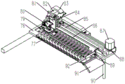
附图中的附图标记所对应的名称为:The names corresponding to the reference signs in the accompanying drawings are:

1-样本模块,2-试剂卡盒模块,3-运输模块,4-摇匀拔帽模块,5-孵育模块,6-控制模块,7-加样模块,8-吸头盒模块,9-驱动机构一,10-传感器一,11-样本支架,12-导向组件二,13-急诊位,14-扫描旋转电机,15-扫描控制板,16-扫码模块,17-传感器二,18-传动组件二,19-驱动机构二,20-样本架限位块,21-样本架支柱,22-光耦一,23-样本拨叉,24-导向组件三,25-传动组件三,26-驱动机构三,27-驱动板卡一,28-导向组件一,29-传动组件一,30-卡盒支撑立板,31-卡盒支撑底板,32-卡盒围板,33-试剂卡盒,34-卡盒隔板,35-卡盒检测传感器,36-光耦二,37-传动组件四,38-导向组件四,39-光缆保护组件一,40-驱动机构六,41-运输拨叉,42-导向组件五,43-驱动机构五,44-驱动机构四,45-运输底板,46-运输仓立柱,47-传动组件五,48-导向组件六,49-运输仓,50-摇匀底板,51-光耦三,52-导向柱一,53-夹紧板,54-导向组件七,55-驱动机构十,56-夹紧推板,57-光耦四,58-驱动机构九,59-支撑加强侧板,60-导向组件八,61-传动组件八,62-转移横板,63-光耦五,64-驱动机构七,65-线缆走线槽,66-驱动机构八,67-夹爪,68-导向组件九,69-支撑立板,70-弹性浮动夹紧块,71-摇匀底座,72-摇匀凸轮板,73-摇匀弹性连接件,74-摇匀转移座,75-摇匀滚轮,76-导向组件十,77-卡条弹簧压片,78-孵育底板,79-温度传感器,80-光学模块,81-光耦六,82-驱动机构十二,83-线缆保护组件二,84-导向件二,85-导向组件十一,86-光学码尺,87-驱动机构十一,88-传动组件十一,89-废卡推板,90-支撑立柱,91-废卡滑槽,92-加热板,93-安装背板,94-驱动板卡二,95-温控板,96-驱动板卡三,97-打印机电源转接板,98-开关电源,99-加样支撑立柱,100-传动组件十三,101-加样横板,102-驱动机构十三,103-导向组件十二,104-光耦七,105-线缆保护组件三,106-驱动机构十四,107-加样纵板,108-导向组件十三,109-线缆保护组件四,110-传动组件十四,111-活塞加样组件,112-导向组件十四,113-驱动机构十五,114-废卡盒挡板,115-滑槽导轨,116-活动底板,117-稀释液灌装瓶,118-吸头盒套装,119-混匀反应盒,120-废物收集盒,121-TIP头卸载板,122-拉手。1-Sample module, 2-Reagent cartridge module, 3-Transportation module, 4-Shake well and cap removal module, 5-Incubation module, 6-Control module, 7-Add sample module, 8-Tip box module, 9- Drive mechanism 1, 10-sensor 1, 11-sample holder, 12-guiding component 2, 13-emergency position, 14-scanning rotating motor, 15-scanning control board, 16-scanning code module, 17-sensor 2, 18- Transmission component 2, 19-driving mechanism 2, 20-sample rack limit block, 21-sample rack pillar, 22-optocoupler 1, 23-sample shift fork, 24-guide component 3, 25-transmission component 3, 26- Drive mechanism three, 27-drive board one, 28-guide component one, 29-transmission component one, 30-cartridge support vertical plate, 31-cartridge support bottom plate, 32-cartridge enclosure, 33-reagent cartridge , 34-cassette partition, 35-cassette detection sensor, 36-optocoupler 2, 37-transmission component 4, 38-guide component 4, 39-optical cable protection component 1, 40-driving mechanism 6, 41-transport dial Fork, 42-guide assembly five, 43-drive mechanism five, 44-drive mechanism four, 45-transport floor, 46-transport warehouse column, 47-transmission assembly five, 48-guide assembly six, 49-transport warehouse, 50- Shake the bottom plate, 51-optocoupler three, 52-guide column one, 53-clamping plate, 54-guide assembly seven, 55-drive mechanism ten, 56-clamping push plate, 57-optocoupler four, 58-drive Mechanism 9, 59-Support and strengthen side plate, 60-Guide component 8, 61-Transmission component 8, 62-Transfer horizontal plate, 63-Optocoupler 5, 64-Drive mechanism 7, 65-Cable routing slot, 66- Drive mechanism eight, 67-gripper, 68-guide component nine, 69-supporting vertical plate, 70-elastic floating clamping block, 71-shake base, 72-shake cam plate, 73-shake elastic connector, - Driving mechanism 12, 83-cable protection component 2, 84-guide component 2, 85-guide component 11, 86-optical yardstick, 87-driving mechanism 11, 88-transmission component 11, 89-waste card Push plate, 90-support column, 91-waste card chute, 92-heating plate, 93-installation back plate, 94-drive board card 2, 95-temperature control board, 96-drive board card 3, 97-printer power supply Adapter board, 98-switching power supply, 99-support column for sample loading, 100-transmission assembly 13, 101-sampling horizontal plate, 102-drive mechanism 13, 103-guiding assembly 12, 104-optocoupler 7, 105-Cable protection component 3, 106-Drive mechanism 14, 107-Sample loading vertical plate, 108-Guide component 13, 109-Cable protection component 4, 110-Transmission component 14, 111-Piston sample loading component , 112-guiding assembly fourteen, 113-driving mechanism fifteen, 114-waste card box baffle, 115-chute guide rail, 116-movable bottom plate, 117-diluent filling bottle, 118-tip box set, 119 -mixing reaction box, 120-waste collection box, 121-TIP head unloading plate, 122-handle.

具体实施方式Detailed ways

为使本发明的目的、技术方案和优点更加清楚明白,下面结合实施例和附图,对本发明作进一步的详细说明,本发明的示意性实施方式及其说明仅用于解释本发明,并不作为对本发明的限定。In order to make the purpose, technical solutions and advantages of the present invention clearer, the present invention will be further described in detail below in conjunction with the examples and accompanying drawings. As a limitation of the present invention.

实施例1:Example 1:

如图1所示,本实施例包括底座,底座是作为整个仪器的支撑装置,是较大的一个平台,保证仪器的稳定性,在底座上设置有样本模块1、试剂卡盒模块2、运输模块3、摇匀拔帽模块4、孵育模块5、控制模块6、加样模块7和吸头盒模块8,其中样本模块1、运输模块2、摇匀拔帽模块3、孵育模块5以及加样模块7均与控制模块6连接;所述运输模块3能够勾取试剂卡盒模块2中的试剂条;所述摇匀拔帽模块4能够对样本模块1中的试管进行翻转以及拔、盖试管帽;所述孵育模块5能够对试剂条进行孵育和采光;所述加样模块7能够吸取样本进行加样。通过这些结构组合,使产品快速检测和反应更具有可控性,检测灵敏度和精密度也有较大提升,也减少人工劳动强度,本方案采光模块化设计,整机集成更加快速灵活。As shown in Figure 1, this embodiment includes a base, the base is used as a supporting device for the entire instrument, and is a relatively large platform to ensure the stability of the instrument. The base is provided with a sample module 1, a reagent cartridge module 2, a transport Module 3, shaking well and cap removal module 4, incubation module 5, control module 6, sample adding module 7 and tip box module 8, wherein sample module 1, transport module 2, shake well and cap removal module 3, incubation module 5 and adding The sample modules 7 are all connected to the control module 6; the transportation module 3 can hook the reagent strips in the reagent cartridge module 2; Test tube cap; the incubation module 5 can incubate the reagent strips and collect light; the sample adding module 7 can draw samples and add samples. Through the combination of these structures, the rapid detection and response of the product are more controllable, the detection sensitivity and precision are also greatly improved, and the labor intensity is also reduced. The lighting modular design of this scheme makes the integration of the whole machine faster and more flexible.

本实施例的工作原理如下:The working principle of this embodiment is as follows:

试剂卡盒模块2中放入不同项目的试剂卡盒并与软件设置相对应→吸头盒模块8中放入tip头和稀释液→样本模块1中放入待测样本→测试软件中录入待测样本测试信息并点击“开始测试”→运输模块3钩取对应项目的试剂卡条→运输到加样位→加样模块7添加tip头并吸取稀释液→加样模块7将稀释液注入混匀反应盒对应反应凹坑内→样本模块1读取样本信息→摇匀拔帽模块4将样本管搬运至摇匀底座中进行摇匀→拔取试管帽→摇匀底座运至加样等待位→加样模块吸取样本→将样本排入混匀反应盒对应凹坑中进行稀释和混匀→加样模块7吸取混匀后的样本排入试剂卡条排样口→运输模块3将卡条运到孵育模块5中进行孵育→采光模块进行采光→运输模块3取出已完成采光的试剂卡条→运输到弃卡位进行弃卡→加样模块7退除tip头→拔帽模块将试管帽合盖→将样本管搬运至试管架→样本模块退除已测样本。Put reagent cartridges of different items in the reagent cartridge module 2 and correspond to the software settings → put tips and diluent in the tip box module 8 → put the sample to be tested in the sample module 1 → enter the test sample in the test software Measure the sample test information and click "Start Test"→transport module 3 hooks the reagent card strip of the corresponding item→transport to the sample adding position→sample adding module 7 adds a tip and sucks the diluent→sample adding module 7 injects the diluent into the mixing chamber The uniform reaction box corresponds to the reaction pit → sample module 1 reads the sample information → shakes the sample tube and pulls the cap module 4 to move the sample tube to the shaking base and shakes it well → pulls out the test tube cap → shakes the base and transports it to the waiting position for adding samples → add The sample module draws the sample → discharges the sample into the corresponding pit of the mixing reaction box for dilution and mixing → the sample adding module 7 draws the mixed sample and discharges it into the sample discharge port of the reagent cartridge → the transportation module 3 transports the cartridge to Incubation in the incubation module 5 → lighting in the lighting module → taking out the reagent cartridges that have been lighted in the transport module 3 → transporting to the card discarding position for discarding the card → removing the tip from the sampling module 7 → closing the cap on the test tube by the cap removal module →Transfer the sample tube to the test tube rack →The sample module removes the tested sample.

实施例2:Example 2:

如图2所示,本实施例样本模块1包括样本支架11,样本支架11下方还设置有底板,底板与底座贴合固定,样本支架11和底板之间通过样本架支柱21来进行连接,这样在样本支架11和底板之间形成安装空间,驱动机构一9、传动组件一29、驱动机构二19、传动组件二18、驱动机构三26和传动组件三25都设置在样本支架11和底板之间,将传动组件一29和驱动机构一9连接并且能够在驱动机构一9带动下传动,传动组件二18和驱动机构二19连接并且能够在驱动机构二19带动下传动,传动组件三25和驱动机构三26连接并且能够在驱动机构三26带动下传动,传动组件一29和传动组件三25的传动方向相同,而传动组件二18的传动方向和传动组件三25的传动方向垂直。在样本支架11下方设置有样本拨叉23,样本拨叉23和传动组件三25连接且能够在传动组件三25带动下相对样本支架11进行水平移动。底板上设置有导向组件一28用于限定与传动组件一29连接的部件移动轨迹,设置有导向组件三24与样本拨叉23连接而限定样本拨叉23的移动轨迹,样本拨叉23顶部能够插入样本支架11底部开设的对应滑道中,样本拨叉23能够沿着滑道移动。样本拨叉23极限位置设置有光耦一22,用于限定其运动距离。通过驱动机构三26带动传动组件三25移动,从而使得样本拨叉23在滑道中移动,从而推动待测样本架在样本支架11上水平移动。设置有导向组件二12来限定与传动组件二18连接的部件移动轨迹,在样本支架11上设置有样本架限位块20来限定样本架移动轨迹,样本支架11上设置有传感器一10和传感器二17实现位置检测。As shown in Figure 2, the sample module 1 of this embodiment includes a sample holder 11, a base plate is also provided under the sample support 11, the base plate and the base are fitted and fixed, and the sample holder 11 and the base plate are connected through the sample rack pillar 21, thus An installation space is formed between the sample holder 11 and the base plate, and the drive mechanism one 9, the transmission assembly one 29, the drive mechanism two 19, the transmission assembly two 18, the drive mechanism three 26 and the transmission assembly three 25 are all arranged between the sample support 11 and the base plate Between, the transmission assembly one 29 is connected with the drive mechanism one 9 and can be driven by the drive mechanism one 9, the transmission assembly two 18 is connected with the drive mechanism two 19 and can be driven by the drive mechanism two 19, and the transmission assembly three 25 and The driving mechanism three 26 is connected and can be driven by the driving mechanism three 26. The transmission direction of the transmission assembly one 29 and the transmission assembly three 25 is the same, and the transmission direction of the transmission assembly two 18 is perpendicular to the transmission direction of the transmission assembly three 25. A sample shift fork 23 is arranged below the sample holder 11 , the sample shift fork 23 is connected to the transmission assembly 3 25 and can move horizontally relative to the sample holder 11 driven by the transmission assembly 3 25 . The bottom plate is provided with guide assembly 1 28 for limiting the moving track of the parts connected with the transmission assembly 1 29, and guide assembly 3 24 is provided to connect with the sample shifting fork 23 to limit the moving track of the sample shifting fork 23, and the top of the sample shifting fork 23 can The sample fork 23 can move along the slideway when it is inserted into the corresponding slideway opened at the bottom of the sample holder 11 . An optocoupler 1 22 is provided at the extreme position of the sample shift fork 23 to limit its movement distance. The driving mechanism 3 26 drives the transmission assembly 3 25 to move, so that the sample fork 23 moves in the slideway, thereby pushing the sample rack to be tested to move horizontally on the sample holder 11 . A guide assembly 2 12 is provided to limit the movement trajectory of the parts connected to the transmission assembly 2 18, a sample rack limit block 20 is arranged on the sample holder 11 to limit the movement trajectory of the sample holder, and the sample holder 11 is provided with a sensor 10 and a sensor 2.17 implements position detection.

在样本支架11外部设置有横向底板,横向底板上安装有扫描旋转电机14、扫描控制板15、扫码模块16,扫描旋转电机14带动扫码模块16动作,横向底板和传动组件二18、导向组件二12连接,通过驱动机构二19带动沿着导向组件二12进行横向移动,同时导向组件二12上连接有横向拨叉,当待测样本架在驱动机构三作用下移动到极限位置时,横向拨叉恰好和测样本架扣合,使得其成为测试样本架,测试样本架相对样本支架11进行水平移动并经过扫描工位进行条码信息读取。A horizontal bottom plate is arranged outside the sample holder 11, and a scanning rotary motor 14, a scanning control board 15, and a code scanning module 16 are installed on the horizontal bottom plate, and the scanning rotary motor 14 drives the scanning code module 16 to move, and the horizontal bottom plate and the transmission assembly 2 18, guide Component 2 12 is connected, driven by the drive mechanism 2 19 to move laterally along the guide component 2 12, and the guide component 2 12 is connected with a horizontal shift fork, when the sample rack to be tested moves to the limit position under the action of the drive mechanism 3, The horizontal shift fork is just engaged with the test sample rack, so that it becomes a test sample rack, and the test sample rack moves horizontally relative to the sample holder 11 and reads the barcode information through the scanning station.

传动组件一29连接有出样拨叉,出样拨叉位于样本支架底部开设的对应滑道中,出样拨叉能够沿着滑道移动。出样拨叉和导向组件一28连接,且出样拨叉能够沿着导向组件一28移动。当扫描完成后移动到预设位置,出样拨叉勾住测试样本架,在驱动机构一9作用下样本架能够相对样本支架11进行水平移动,同时解除和传动组件二18中同步带的连接关系,随着移动测试样本架成为已测样本架。还在样本支架11预留有急诊位13,进一步提升配套整机的应用场景。The transmission component one 29 is connected with a sample delivery fork, which is located in a corresponding slideway provided at the bottom of the sample holder, and the sample delivery fork can move along the slideway. The sample-out fork is connected to the first guide assembly 28 , and the sample-out fork can move along the first guide assembly 28 . After the scanning is completed, move to the preset position, the sample-out fork hooks the test sample rack, and the sample rack can move horizontally relative to the sample holder 11 under the action of the driving mechanism 19, and at the same time release the connection with the timing belt in the transmission assembly 2 18 relationship, as the moving test sample rack becomes the tested sample rack. An emergency room 13 is also reserved in the sample holder 11 to further enhance the application scenarios of the complete machine.

将待测样本放入样本支架11的待测样本架中,样本架放入时需注意底部缺口须与样本架限位块20对齐(防呆功能),驱动机构三26与传动组件三25和进样拨叉一同动作将样本架移动到预设位置,并设置有传感器二17对其状态进行检测;驱动机构二19与传动组件二18一同动作将样本架移动到预设位置由扫码模块16进行条码信息读取;对样本进行处理后驱动机构一9与传动组件一29和出样拨叉一同动作将样本架移动到预设位置,并通过传感器一10对其状态进行检测;并在样本装置中设置有急诊位13,以增加配套仪器的应用环境。本方案可实现自动移动样本架;可实现自动读取样本信息;可实现样本架到位检测;可实现急诊样本独立放置;可实现同时放入多组样本架;可实现样本架放置方向限位。Put the sample to be tested into the sample rack to be tested in the sample holder 11. When the sample rack is put in, it is necessary to pay attention to the bottom gap must be aligned with the sample rack limit block 20 (fool-proof function), the driving mechanism 3 26 and the transmission assembly 25 and The sampling fork works together to move the sample rack to the preset position, and is equipped with a sensor 2 17 to detect its state; the driving mechanism 2 19 and the transmission assembly 2 18 work together to move the sample rack to the preset position and the code scanning module 16 to read the barcode information; after the sample is processed, the driving mechanism-9, the transmission component-29 and the sample fork work together to move the sample rack to the preset position, and detect its state through the sensor-10; and An emergency position 13 is arranged in the sample device to increase the application environment of supporting instruments. This solution can realize automatic movement of sample racks; automatic reading of sample information; detection of in-place detection of sample racks; independent placement of emergency samples; simultaneous placement of multiple sets of sample racks; and limit position of the placement direction of sample racks.

实施例3:Example 3:

如图3所示,本实施例试剂卡盒模块2包括与底座连接的卡盒支撑架,卡盒支撑架上设置有卡盒隔板34,卡盒隔板34之间预留有放置试剂卡盒33的空间。卡盒支撑架是由卡盒支撑立板30、卡盒支撑底板31、卡盒围板32构成,卡盒支撑立板30与底座连接,卡盒支撑底板31与卡盒支撑立板30顶部固定,卡盒围板32沿着卡盒支撑底板31顶部围绕形成内部中空结构,卡盒隔板34在中空结构中,将试剂卡盒33放入各个预设卡槽位置,卡槽位置与卡盒检测种类通过软件设置一一对应,相对应的卡盒放入对应的卡槽位,并设置有检测传感器35可对试剂卡盒33的放置状态进行实时监测。卡盒围板32前面留有勾卡缺口,方便运输模块将卡盒中的试剂卡勾入运输模块中。As shown in Figure 3, the reagent cartridge module 2 of this embodiment includes a cartridge support frame connected to the base, a cartridge partition 34 is arranged on the cartridge support frame, and a reagent card is reserved between the cartridge partitions 34. Box 33 space. The cassette support frame is made of a cassette support vertical plate 30, a cassette support base plate 31, and a cassette coaming plate 32. The cassette support vertical plate 30 is connected with the base, and the cassette support base plate 31 is fixed to the top of the cassette support vertical plate 30. , the cassette coaming plate 32 forms an internal hollow structure along the top of the cassette support base plate 31, the cassette partition 34 is in the hollow structure, and the reagent cassette 33 is put into each preset slot position, and the slot position is the same as that of the cassette The detection types are set in one-to-one correspondence through the software, and the corresponding cartridges are placed in the corresponding card slots, and a detection sensor 35 is provided to monitor the placement status of the reagent cartridges 33 in real time. There is a hook gap in the front of the cassette coaming plate 32, which is convenient for the transport module to hook the reagent cards in the cassette into the transport module.

实施例4:Example 4:

如图4所示,本实施例运输模块3包括运输底板45、驱动机构四44和传动组件四37,驱动机构四44和传动组件四37均固定在底座上,且传动组件四37和驱动机构四44连接并且能够在驱动机构四44带动下传动,运输底板45和传动组件四37连接且能够在传动组件四37带动下相对底座进行水平移动,运输底板45通过导向组件四38进行移动限位和导向,导向组件四38安装在底座上,运输底板45上还设置有光缆保护组件一39。在运输底板45上设置有驱动机构五43、传动组件五47、驱动机构六40、传动组件六、运输拨叉41和运输仓49,运输仓49通过运输仓立柱46与运输底板45连接,形成一定的高度。传动组件五47和驱动机构五43连接并且能够在驱动机构五43带动下传动,传动组件六和驱动机构六40作为一个整体与传动组件五47连接且能够在传动组件五47带动下相对运输底板45进行水平移动,并且配有导向组件六48进行移动限位和导向,传动组件六和驱动机构六40连接并且能够在驱动机构六40带动下传动,运输拨叉41和和传动组件六连接且能够在传动组件六带动下相对运输底板45进行竖直移动并且能够插入和拔出运输仓49,配有导向组件五42进行移动限位和导向。运输拨叉41在驱动机构六40驱动下可实现垂直方向的运动,在驱动机构五的驱动下可沿导向组件六48实现其纵向运动,在驱动机构四44的驱动下可沿导向组件四38实现其横向运动。最终可将试剂卡运输到各个预设位置和从孵育模块的各个预设位置中取出试剂卡放入运输仓49中。辅以传感器和光耦二36可实现对试剂卡的状态进行监测,再配以码尺可实现闭环控制以提高整个模块的运动精度。As shown in Figure 4, the transportation module 3 of this embodiment includes a transportation base plate 45, a driving mechanism 44 and a transmission assembly 37, the driving mechanism 44 and the transmission assembly 37 are all fixed on the base, and the transmission assembly 437 and the driving mechanism 44 is connected and can be driven by the driving mechanism 444. The transport base plate 45 is connected to the transmission assembly 437 and can move horizontally relative to the base under the drive of the transmission assembly 437. The transport base plate 45 is limited by the guide assembly 438. And guide, the guide assembly four 38 is installed on the base, and the optical cable protection assembly one 39 is also arranged on the transportation base plate 45 . On the transport base plate 45 are provided with drive mechanism five 43, transmission assembly five 47, drive mechanism six 40, transmission assembly six, transport shift fork 41 and transport bin 49, and transport bin 49 is connected with transport base plate 45 by transport bin column 46 to form a certain height. Transmission assembly five 47 is connected to drive mechanism five 43 and can be driven by drive mechanism five 43. Transmission assembly six and drive mechanism six 40 are connected to transmission assembly five 47 as a whole and can be driven by transmission assembly five 47 to relatively transport the bottom plate 45 moves horizontally, and is equipped with guide assembly 6 48 to carry out movement limit and guide, transmission assembly 6 is connected with drive mechanism 6 40 and can drive under the drive of drive mechanism 6 40, transport shift fork 41 is connected with transmission assembly 6 and It can move vertically relative to the transport base plate 45 driven by the transmission assembly six and can insert and pull out the transport bin 49, and is equipped with a guide assembly five 42 for movement limit and guidance. The transport shift fork 41 can realize vertical movement under the driving of the driving mechanism 6 40, and can realize its longitudinal movement along the guiding assembly 6 48 under the driving of the driving mechanism 5, and can move along the guiding assembly 4 38 under the driving of the driving mechanism 444. achieve its lateral movement. Finally, the reagent card can be transported to each preset position and the reagent card can be taken out from each preset position of the incubation module and put into the transport bin 49 . Auxiliary sensor and optocoupler 236 can monitor the state of the reagent card, coupled with yardstick can realize closed-loop control to improve the movement accuracy of the whole module.

实施例5:Example 5:

如图5所示,本实施例摇匀拔帽模块4包括与底座固定的摇匀底板50,摇匀底板50上方垂直固定有支撑立板69,为了增加稳定性,在支撑立板69侧部还设置有支撑加强侧板59来增加结构稳定性。支撑立板69安装有线缆走线槽65,支撑立板69上设置有驱动机构七64和传动组件七,传动组件七和驱动机构七64连接并且能够在驱动机构七64带动下传动,传动组件七连接转移横板62,转移横板62能够在传动组件七带动下相对支撑立板69进行竖直移动;所述转移横板62上设置有驱动机构八66和传动组件八61,传动组件八61和驱动机构八66连接并且能够在驱动机构八66带动下传动,传动组件八61连接有夹爪67,夹爪67能够在传动组件八61带动下相对转移横板62进行水平移动;所述支撑立板69上设置有驱动机构九58、传动组件九、驱动机构十55和传动组件十,传动组件九和驱动机构九58连接并且能够在驱动机构九58带动下传动,传动组件九连接有夹紧推板56,夹紧推板56能够在传动组件九带动下相对支撑立板69进行竖直移动,夹紧推板56连接有导向组件七54,导向组件七54和支撑立板69固定,实现夹紧推板56的导向和限位。传动组件十和驱动机构十55连接并且能够在驱动机构十55带动下传动,驱动机构十55连接有摇匀转移座74,摇匀转移座74和摇匀底板50连接,摇匀底板50上设置有导向组件十76,导向组件十76和摇匀转移座74连接,且摇匀转移座74能够在传动组件十带动下沿着导向组件十76相对摇匀底板50进行水平移动,摇匀转移座74上设置有摇匀底座71,摇匀转移座74和摇匀底座71通过同一根销轴连接,摇匀底座71能够绕着销轴的轴线转动。As shown in Figure 5 , the shaker and cap removal module 4 of this embodiment includes a shaker base plate 50 fixed to the base, and a support vertical plate 69 is vertically fixed above the shaker base plate 50 . Support reinforcement side panels 59 are also provided to increase structural stability. The support vertical plate 69 is equipped with a cable routing groove 65, and the support vertical plate 69 is provided with a driving mechanism 7 64 and a transmission assembly 7, and the transmission assembly 7 and the driving mechanism 64 are connected and can be driven by the driving mechanism 64. The component seven is connected to the transfer horizontal plate 62, and the transfer horizontal plate 62 can move vertically relative to the supporting vertical plate 69 under the drive of the transmission component seven; Eight 61 is connected with the drive mechanism eight 66 and can be driven by the drive mechanism eight 66. The transmission assembly eight 61 is connected with a jaw 67, and the jaw 67 can move horizontally relative to the transfer horizontal plate 62 driven by the transmission assembly eight 61; The support vertical plate 69 is provided with driving mechanism 9 58, transmission assembly 9, driving mechanism 10 55 and transmission assembly 10, the transmission assembly 9 is connected with the driving mechanism 9 58 and can be driven by the driving mechanism 9 58, and the transmission assembly 9 is connected Clamping push plate 56 is arranged, and clamping push plate 56 can carry out vertical movement relative to support vertical plate 69 under the driving of transmission assembly nine, and clamping push plate 56 is connected with guide assembly seven 54, guide assembly seven 54 and support vertical plate 69 Fix to realize the guiding and positioning of the clamping push plate 56. The transmission assembly 10 is connected with the driving mechanism 10 55 and can be driven by the driving mechanism 10 55. The driving mechanism 10 55 is connected with a shaker transfer seat 74, and the shaker transfer seat 74 is connected with the shaker base plate 50, and the shaker base plate 50 is provided with There is a guide assembly 10 76, which is connected to the shaking transfer seat 74, and the shaking transfer seat 74 can move horizontally along the guide assembly 10 76 relative to the shaking base plate 50 under the drive of the transmission assembly 10, and the shaking transfer seat 74 is provided with a shaker base 71, and the shaker transfer seat 74 and the shaker base 71 are connected by the same pin shaft, and the shaker base 71 can rotate around the axis of the pin shaft.

支撑立板69上设置有夹紧板53,夹紧板53能够相对支撑立板69进行水平移动,夹紧板53上设置有导向柱一52,导向柱一52穿过夹紧板53与支撑立板69固定,起着导向和限位作用。夹紧板53上设置有弹性浮动夹紧块70,弹性浮动夹紧块70受到挤压后能够与摇匀底座71卡紧;在摇匀底座71上设置有摇匀凸轮板72,摇匀底板50安装有摇匀滚轮75,在摇匀转移座74水平移动时摇匀凸轮板72能够与摇匀滚轮75接触实现摇匀底座71的转动,摇匀转移座74上设置有摇匀弹性连接件73,摇匀弹性连接件73同时与摇匀转移座74和摇匀凸轮板72连接。The support vertical plate 69 is provided with a clamping plate 53, and the clamping plate 53 can move horizontally relative to the support vertical plate 69. The clamping plate 53 is provided with a guide post-52, and the guide post-52 passes through the clamping plate 53 and supports Riser 69 is fixed, plays guiding and position-limiting effect. The clamping plate 53 is provided with an elastic floating clamping block 70, which can be clamped with the shaking base 71 after being squeezed; the shaking base 71 is provided with a shaking cam plate 72, and the shaking base 50 is equipped with a shaker roller 75, and the shaker cam plate 72 can contact with the shaker roller 75 to realize the rotation of the shaker base 71 when the shaker transfer seat 74 moves horizontally, and the shaker transfer seat 74 is provided with a shaker elastic connector 73, the shaken elastic connector 73 is connected with the shaken transfer base 74 and the shaken cam plate 72 at the same time.

电动夹爪67在驱动机构八66的驱动下可沿导向组件八60横向运行将样本管从样本模块上取出并放入摇匀底座71里,驱动机构十55驱动带动摇匀底座71及样本管沿导向组件十76前进,当摇匀凸轮板72与摇匀滚轮75接触后摇匀底座71将做90度摆动运动,摇匀底座71回退时在摇匀弹性连接件73的作用下旋转恢复原位,如此反复运行带动样本管摆动摇匀。摇匀后摇匀底座71回到初始位置,驱动机构九58作为夹紧驱动机构来驱动夹紧推板56向下运动,导致夹紧板53和弹性浮动夹紧块70前移从而夹紧样本管,随后电动夹爪67在驱动机构七64的驱动下沿着导向组件九68上下运行完成拔帽和盖帽动作。分别设置有光耦三51、光耦四54、光耦五63来检测移动位置。Driven by the driving mechanism 8 66, the electric gripper 67 can run laterally along the guide assembly 8 60 to take out the sample tube from the sample module and put it into the shaking base 71, and the driving mechanism 10 55 drives the shaking base 71 and the sample tube Advance along the guide assembly ten 76, when the shaking cam plate 72 contacts with the shaking roller 75, the shaking base 71 will make a 90-degree swing movement, and when the shaking base 71 retreats, it will rotate and recover under the action of the shaking elastic connector 73 In situ, such repeated operation drives the sample tube to shake and shake well. After shaking well, shake the base 71 back to the initial position, and the driving mechanism 9 58 acts as a clamping driving mechanism to drive the clamping push plate 56 to move downward, causing the clamping plate 53 and the elastic floating clamping block 70 to move forward to clamp the sample Pipe, then the electric jaw 67 runs up and down along the guide assembly nine 68 under the drive of the drive mechanism seven 64 to complete the action of pulling out the cap and blocking the cap. Optocoupler 3 51 , optocoupler 4 54 , and optocoupler 5 63 are respectively provided to detect the moving position.

实施例6:Embodiment 6:

如图6所示,本实施例孵育模块5包括与底座连接的孵育底板78,孵育底板78通过支撑立柱90与底座固定,孵育底板78上设置有卡条弹簧压片77来安装试剂卡条,孵育底板78上设置有线缆保护组件二83。在孵育底板78上设置有驱动机构十一87和传动组件十一88,传动组件十一88和驱动机构十一87连接并且能够在驱动机构十一87带动下传动,驱动机构十一87连接有采光模块,且采光模块能够在驱动机构十一87带动下相对孵育底板78水平移动,采光模块上设置有光耦六81来进行位置检测,孵育底板78上安装有导向组件十一85与采光模块连接限定移动轨迹。而采光模块包括驱动机构十二82和传动组件十二,传动组件十二和驱动机构十二82连接并且能够在驱动机构十二82带动下传动,传动组件十二连接有光学模块80,且光学模块80能够在传动组件十二带动下相对孵育底板78水平移动。采光模块中还设置有导向件二84来实现移动导向和限位。As shown in Figure 6, the incubation module 5 of this embodiment includes an incubation bottom plate 78 connected to the base, the incubation bottom plate 78 is fixed to the base through a supporting column 90, and a strip spring pressing piece 77 is provided on the incubation bottom plate 78 to install the reagent strip. A cable protection assembly 2 83 is arranged on the incubation bottom plate 78 . On the incubation bottom plate 78, a driving mechanism eleven 87 and a transmission assembly eleven 88 are arranged. The transmission assembly eleven 88 is connected with the driving mechanism eleven 87 and can be driven by the driving mechanism eleven 87. The driving mechanism eleven 87 is connected with The lighting module, and the lighting module can move horizontally relative to the incubation base plate 78 driven by the driving mechanism 11 87, the lighting module is provided with an optocoupler 6 81 for position detection, and the guiding assembly 11 85 and the lighting module are installed on the incubation base plate 78 Connections define movement trajectories. The daylighting module includes a driving mechanism 12 82 and a transmission assembly 12, the transmission assembly 12 is connected to the driving mechanism 12 82 and can be driven by the driving mechanism 12 82, the transmission assembly 12 is connected with an optical module 80, and the optical The module 80 can move horizontally relative to the incubation bottom plate 78 driven by the transmission assembly 12 . The daylighting module is also provided with a guide part 2 84 to realize movement guidance and position limitation.

运输模块3将试剂卡条运输至孵育模块5后,试剂卡先进行试剂反应,待其完成反应后采光模块在驱动机构十一和驱动机构十二的共同作用下,可实现横向及纵向运动,最终通过光学模块80实现对不同孵育位置的试剂卡进行采光。运输模块3将完成采光的试剂卡条运输至孵育底板78出料位置,驱动驱动机构十一驱动光学模块80推动废卡推板89(可弹性复位)将试剂卡推到废卡滑槽91内,试剂卡沿斜面掉落。配以光学码齿86可实现闭环控制以提高整个模块的采光运动精度,温度传感器79可精确检测卡条反应温度,配合加热板92精确控制整个孵育模块的反应温度。After the transport module 3 transports the reagent strips to the incubation module 5, the reagent card first performs the reagent reaction. After the reaction is completed, the lighting module can realize horizontal and vertical movement under the joint action of the driving mechanism 11 and the driving mechanism 12. Finally, the optical module 80 realizes lighting the reagent cards at different incubation positions. The transportation module 3 transports the reagent card strips that have completed daylighting to the discharge position of the incubation bottom plate 78, and drives the driving mechanism 11 to drive the optical module 80 to push the waste card push plate 89 (returnable elastically) to push the reagent card into the waste card chute 91 , the reagent card falls along the slope. Equipped with optical code teeth 86, closed-loop control can be realized to improve the accuracy of the lighting movement of the entire module. The temperature sensor 79 can accurately detect the reaction temperature of the strips, and cooperate with the heating plate 92 to accurately control the reaction temperature of the entire incubation module.

实施例7:Embodiment 7:

如图7所示,本实施例的控制模块6包括安装背板93,安装背板93上设置有驱动板卡二94、温控板95、驱动板卡三96、打印机电源转接板97和开关电源98,通过这些结构对工作过程进行精确控制,这些都是现有结构,能够直接购买到。As shown in Figure 7, the control module 6 of this embodiment includes an installation backplane 93, on which the installation backplane 93 is provided with a drive board two 94, a temperature control board 95, a drive board three 96, a printer power adapter board 97 and The switching power supply 98 precisely controls the working process through these structures, which are all existing structures and can be purchased directly.

实施例8:Embodiment 8:

如图8所示,本实施例加样模块7包括加样横板101,加样横板101通过加样支撑立柱99与底座连接,加样支撑立柱99上安装有废卡盒挡板114。在加样横板101上设置有线缆保护组件三105、光耦七104、驱动机构十三102和传动组件十三100,传动组件十三100和驱动机构十三102连接并且能够在驱动机构十三102带动下传动,传动组件十三100连接有加样纵板107,加样纵板107能够在传动组件十三100带动下相对加样横板101水平移动,加样横板101上设置有导向组件十二103,加样纵板107和导向组件十二103连接并且实现移动导向限位。所述加样纵板107上设置有线缆保护组件四109、驱动机构十四106和传动组件十四110,传动组件十四110和驱动机构十四106连接并且能够在驱动机构十四106带动下传动,传动组件十四110连接有加样组件,加样组件能够在传动组件十四110带动下相对加样纵板107水平移动,加样纵板107上设置有导向组件十三108,导向组件十三108和加样组件连接并且实现移动导向限位。所述加样组件包括驱动机构十五113和传动组件十五,传动组件十五和驱动机构十五113连接并且能够在驱动机构十五113带动下传动,传动组件十五连接有活塞加样组件111,活塞加样组件111能够在传动组件十五带动下相对加样纵板竖直移动,活塞加样组件111连接有枪头。加样组件中设置有导向组件十四112,导向组件十四112与活塞加样组件111连接实现移动导向限位。As shown in FIG. 8 , the sample loading module 7 of this embodiment includes a sample loading horizontal plate 101 . The sample loading horizontal plate 101 is connected to the base through a sample loading support column 99 , and a waste cassette baffle 114 is installed on the sample loading support column 99 . A cable protection assembly three 105, an optocoupler seven 104, a drive mechanism thirteen 102, and a transmission assembly thirteen 100 are arranged on the sample loading horizontal plate 101, and the transmission assembly thirteen 100 is connected with the drive mechanism thirteen 102 and can Driven by 13 102, the transmission component 13 100 is connected with a sample loading vertical plate 107, and the sample loading vertical plate 107 can move horizontally relative to the sample loading horizontal plate 101 driven by the transmission component 13 100, and the sample loading horizontal plate 101 is set There is a guide assembly 12 103, and the sample loading vertical plate 107 is connected with the guide assembly 12 103 and realizes movement guide limit. The sample loading vertical plate 107 is provided with a cable protection assembly 14 109, a driving mechanism 14 106 and a transmission assembly 14 110, and the transmission assembly 14 110 is connected to the driving mechanism 14 106 and can be driven by the driving mechanism 14 106. The lower transmission, the transmission assembly 14 110 is connected with the sample loading assembly, which can move horizontally relative to the sample loading vertical plate 107 driven by the transmission assembly 14 110, and the sample loading vertical plate 107 is provided with a guide assembly 13 108, guiding Component 13 108 is connected with the sample loading component and realizes movement guide limit. The sample adding assembly includes a driving mechanism 15 113 and a transmission assembly 15, the transmission assembly 15 is connected to the driving mechanism 15 113 and can be driven by the driving mechanism 15 113, and the transmission assembly 15 is connected with a piston sample adding assembly 111, the piston sample adding assembly 111 can move vertically relative to the sample adding longitudinal plate driven by the transmission assembly 15, and the piston sample adding assembly 111 is connected with a gun head. The sample adding assembly is provided with a guide assembly 14 112, and the guide assembly 14 112 is connected with the piston sample adding assembly 111 to realize movement guide and limit.

驱动机构十三102运动可实现活塞加样组件111(包含但不限于柱塞泵)在导向组件十二103上横向运动;驱动机构十四106运动可实现活塞加样组件111(包含但不限于柱塞泵)在导向组件十三108上纵向运动;活塞加样组件111(包含但不限于柱塞泵)在驱动机构十五113的驱动下可实现前端枪头的垂直方向运动,配以横向及纵向,可实现枪头三个维度的运动,即运动到各个预设位置。The movement of the driving mechanism 13 102 can realize the lateral movement of the piston sample feeding assembly 111 (including but not limited to the plunger pump) on the guide assembly 12 103; the movement of the driving mechanism 14 106 can realize the piston sample feeding assembly 111 (including but not limited to) The plunger pump) moves longitudinally on the guide assembly 13 108; the piston sampling assembly 111 (including but not limited to the plunger pump) can realize the vertical movement of the tip of the front end under the drive of the drive mechanism 15 113, and is equipped with a horizontal And vertically, it can realize the three-dimensional movement of the gun head, that is, to move to each preset position.

实施例9:Embodiment 9:

如图9所示,本实施例吸头盒模块8包括与底座连接的活动底板116,且活动底板116能够相对底座进行水平移动,并且通过滑槽导轨115进行移动导向和限位。活动底板116上设置有稀释液安装板、吸头盒安装板和反应盒安装板,稀释液灌装瓶117安装在稀释液安装板上,吸头盒套装118安装在吸头盒安装板上,混匀反应盒119安装在反应盒安装板上,吸头盒安装板下方设置有TIP头卸载板121,TIP头卸载板121下方设置有废物收集盒120。通过拉手122手动拉出吸头盒模块完成稀释液的更换、吸头盒套装和混匀反应盒的更换,更换后再推到预设位置等待枪头来吸头盒套装118上装载TIP头以及加载稀释液和样本至混匀反应盒119中混匀等。通过TIP头卸载板121完成枪头的自动卸载并收集至废物收集盒120内。As shown in FIG. 9 , the tip box module 8 of this embodiment includes a movable bottom plate 116 connected to the base, and the movable bottom plate 116 can move horizontally relative to the base, and is guided and limited by the chute guide rail 115 . The movable bottom plate 116 is provided with a diluent mounting plate, a tip box mounting plate and a reaction box mounting plate, the diluent filling bottle 117 is mounted on the diluent mounting plate, and the tip box suit 118 is mounted on the tip box mounting plate, The mixing reaction box 119 is installed on the reaction box mounting plate, a TIP head unloading plate 121 is arranged under the tip box mounting plate, and a waste collection box 120 is arranged under the TIP head unloading plate 121 . Pull out the tip box module manually through the handle 122 to complete the replacement of the diluent, the tip box set and the mixing reaction box, and then push it to the preset position to wait for the tip to be loaded on the tip box set 118 and the Load the diluent and sample into the mixing reaction box 119 for mixing and so on. The automatic unloading of the gun tip is completed through the TIP tip unloading plate 121 and collected into the waste collection box 120 .

以上的具体实施方式,对本发明的目的、技术方案和有益效果进行了进一步详细说明,所应理解的是,以上仅为本发明的具体实施方式而已,并不用于限定本发明的保护范围,凡在本发明的精神和原则之内,所做的任何修改、等同替换、改进等,均应包含在本发明的保护范围之内。The above specific implementation manners have further described the purpose, technical solutions and beneficial effects of the present invention in detail. It should be understood that the above are only specific implementation modes of the present invention, and are not used to limit the protection scope of the present invention. Within the spirit and principles of the present invention, any modifications, equivalent replacements, improvements, etc., shall be included in the protection scope of the present invention.

Claims (10)

1. The utility model provides a full-automatic dry type fluorescence immunoassay appearance, includes the base, its characterized in that: the base is provided with a sample module (1), a reagent card box module (2), a transportation module (3), a shaking cap pulling module (4), an incubation module (5), a control module (6), a sample adding module (7) and a suction head box module (8), wherein the sample module (1), the transportation module (2), the shaking cap pulling module (3), the incubation module (5) and the sample adding module (7) are all connected with the control module (6); the transport module (3) can hook the reagent strips in the reagent card box module (2); the shaking cap-pulling module (4) can turn over the test tube in the sample module (1) and pull and cover the test tube cap; the incubation module (5) can incubate and collect light for the reagent strip; the sample adding module (7) can absorb a sample to add the sample.
2. The fully automatic dry type fluoroimmunoassay analyzer according to claim 1, characterized in that: the sample module (1) comprises a sample support (11), the sample support (11) is installed on a base, a first driving mechanism (9), a first transmission assembly (29), a second driving mechanism (19), a second transmission assembly (18), a third driving mechanism (26) and a third transmission assembly (25) are arranged below the sample support (11), the first transmission assembly (29) is connected with the first driving mechanism (9) and can drive to transmit under the driving of the first driving mechanism (9), the second transmission assembly (18) is connected with the second driving mechanism (19) and can drive to transmit under the driving of the second driving mechanism (19), the third transmission assembly (25) is connected with the third driving mechanism (26) and can drive to transmit under the driving of the third driving mechanism (26), the first transmission assembly (29) and the third transmission assembly (25) are identical in transmission direction, and the second transmission assembly (18) is perpendicular to the third transmission assembly (25).
3. The fully automatic dry type fluoroimmunoassay analyzer according to claim 2, characterized in that: a sample shifting fork (23) is arranged below the sample support (11), the sample shifting fork (23) is connected with a transmission assembly III (25) and can be driven by the transmission assembly III (25) to move horizontally relative to the sample support (11).
4. The fully automatic dry type fluoroimmunoassay analyzer according to claim 1, characterized in that: the transportation module (3) comprises a transportation bottom plate (45), a driving mechanism IV (44) and a transmission assembly IV (37), the driving mechanism IV (44) and the transmission assembly IV (37) are fixed on the base, the transmission assembly IV (37) is connected with the driving mechanism IV (44) and can be driven by the driving mechanism IV (44) to transmit, and the transportation bottom plate (45) is connected with the transmission assembly IV (37) and can be driven by the transmission assembly IV (37) to horizontally move relative to the base; the conveying bottom plate (45) is provided with a fifth driving mechanism (43), a fifth transmission assembly (47), a sixth driving mechanism (40), a sixth transmission assembly, a conveying shifting fork (41) and a conveying bin (49), the fifth transmission assembly (47) is connected with the fifth driving mechanism (43) and can be driven by the fifth driving mechanism (43) to transmit, and the sixth driving mechanism (40) is connected with the fifth transmission assembly (47) and can be driven by the fifth transmission assembly (47) to horizontally move relative to the conveying bottom plate (45); six and the actuating mechanism of drive assembly (40) are connected and can drive the underdrive at six (40) of actuating mechanism, and transportation shift fork (41) and with six the connection of drive assembly and can carry out vertical movement and can insert and extract transport bin (49) relative to transportation bottom plate (45) under six drives of drive assembly.
5. The fully automatic dry type fluoroimmunoassay analyzer according to claim 1, characterized in that: the shaking-up cap-pulling module (4) comprises a shaking-up bottom plate (50) fixed with the base, a supporting vertical plate (69) is vertically fixed above the shaking-up bottom plate (50), a driving mechanism seven (64) and a transmission assembly seven are arranged on the supporting vertical plate (69), the transmission assembly seven and the driving mechanism seven (64) are connected and can be driven by the driving mechanism seven (64) to perform transmission, the transmission assembly seven is connected with a transfer transverse plate (62), and the transfer transverse plate (62) can vertically move relative to the supporting vertical plate (69) under the driving of the transmission assembly seven; the transfer transverse plate (62) is provided with an eight driving mechanism (66) and an eight transmission assembly (61), the eight transmission assembly (61) is connected with the eight driving mechanism (66) and can be driven by the eight driving mechanism (66) to transmit, the eight transmission assembly (61) is connected with a clamping jaw (67), and the clamping jaw (67) can be driven by the eight transmission assembly (61) to horizontally move relative to the transfer transverse plate (62); support and be provided with actuating mechanism nine (58) on riser (69), drive assembly nine, actuating mechanism ten (55) and drive assembly ten, drive assembly nine is connected with actuating mechanism nine (58) and can drive the underdrive at actuating mechanism nine (58), drive assembly nine is connected with and presss from both sides tight push pedal (56), it can carry out vertical movement to support riser (69) under drive assembly nine drives to press from both sides tight push pedal (56), drive assembly ten is connected with drive mechanism ten (55) and can drive the underdrive at actuating mechanism ten (55), actuating mechanism ten (55) are connected with and shake even transfer seat (74), it transfers seat (74) and shakes even bottom plate (50) and connect to shake even, and shake even transfer seat (74) and can shake even bottom plate (50) and carry out horizontal migration relatively under drive assembly ten drives, it is provided with on transferring seat (74) and shakes even base (71), it can rotate around the junction with shaking even transfer seat (74) to shake even base (71).
6. The fully automatic dry type fluoroimmunoassay analyzer according to claim 5, characterized in that: the supporting vertical plate (69) is provided with a clamping plate (53), the clamping plate (53) can horizontally move relative to the supporting vertical plate (69), the clamping plate (53) is provided with an elastic floating clamping block (70), and the elastic floating clamping block (70) can be in contact with the shaking base (71) after being extruded; shake even base (71) and be provided with on and shake even cam plate (72), shake even bottom plate (50) and install and shake even gyro wheel (75), shake even cam plate (72) and can with shake even gyro wheel (75) contact when shaking even transfer seat (74) horizontal migration and realize shaking the rotation of even base (71), shake even transfer and be provided with on the seat (74) and shake even elastic connecting piece (73), shake even elastic connecting piece (73) simultaneously with shake even transfer seat (74) and shake even cam plate (72) and be connected.
7. The fully automatic dry fluoroimmunoassay analyzer of claim 1, wherein: the incubation module (5) comprises an incubation bottom plate (78) connected with the base, wherein the incubation bottom plate (78) is provided with an eleventh driving mechanism (87) and an eleventh transmission assembly (88), the eleventh transmission assembly (88) is connected with the eleventh driving mechanism (87) and can be driven by the eleventh driving mechanism (87) to transmit, the eleventh driving mechanism (87) is connected with a lighting module, and the lighting module can be driven by the eleventh driving mechanism (87) to horizontally move relative to the incubation bottom plate (78); the lighting module comprises a driving mechanism twelve (82) and a transmission assembly twelve, the transmission assembly twelve is connected with the driving mechanism twelve (82) and can transmit under the driving of the driving mechanism twelve (82), the transmission assembly twelve is connected with an optical module (80), and the optical module (80) can relatively incubate the horizontal movement of the bottom plate (78) under the driving of the transmission assembly twelve.
8. The fully automatic dry type fluoroimmunoassay analyzer according to claim 1, characterized in that: the sample adding module (7) comprises a sample adding transverse plate (101) connected with the base, a driving mechanism thirteen (102) and a transmission assembly thirteen (100) are arranged on the sample adding transverse plate (101), the transmission assembly thirteen (100) is connected with the driving mechanism thirteen (102) and can be driven by the driving mechanism thirteen (102) to transmit, the transmission assembly thirteen (100) is connected with a sample adding longitudinal plate (107), and the sample adding longitudinal plate (107) can be driven by the driving assembly thirteen (100) to horizontally move relative to the sample adding transverse plate (101); a driving mechanism fourteen (106) and a transmission assembly fourteen (110) are arranged on the sample adding longitudinal plate (107), the transmission assembly fourteen (110) is connected with the driving mechanism fourteen (106) and can transmit under the driving of the driving mechanism fourteen (106), the transmission assembly fourteen (110) is connected with a sample adding assembly, and the sample adding assembly can horizontally move relative to the sample adding longitudinal plate (107) under the driving of the transmission assembly fourteen (110); the sample adding component comprises a driving mechanism fifteen (113) and a transmission component fifteen, the transmission component fifteen is connected with the driving mechanism fifteen (113) and can be driven by the driving mechanism fifteen (113) to transmit, the transmission component fifteen is connected with a piston sample adding component (111), the piston sample adding component (111) can vertically move relative to the sample adding longitudinal plate under the driving of the transmission component fifteen, and the piston sample adding component (111) is connected with a gun head.
9. The fully automatic dry type fluoroimmunoassay analyzer according to claim 1, characterized in that: the suction head box module (8) comprises a movable bottom plate (116) connected with the base, the movable bottom plate (116) can move horizontally relative to the base, a diluent mounting plate, a suction head box mounting plate and a reaction box mounting plate are arranged on the movable bottom plate (116), and a TIP head unloading plate (121) is arranged below the suction head box mounting plate.
10. The fully automatic dry type fluoroimmunoassay analyzer according to claim 1, characterized in that: the reagent card box module (2) comprises a card box support frame connected with the base, a card box partition plate (34) is arranged on the card box support frame, and a space for placing the reagent card box (33) is reserved between the card box partition plate (34).
CN202211564527.8A 2022-12-07 2022-12-07 A fully automatic dry fluorescent immunoassay analyzer Withdrawn CN115808536A (en)

Priority Applications (1)

Application Number Priority Date Filing Date Title
CN202211564527.8A CN115808536A (en) 2022-12-07 2022-12-07 A fully automatic dry fluorescent immunoassay analyzer

Applications Claiming Priority (1)

Application Number Priority Date Filing Date Title
CN202211564527.8A CN115808536A (en) 2022-12-07 2022-12-07 A fully automatic dry fluorescent immunoassay analyzer

Publications (1)

Publication Number Publication Date
CN115808536A true CN115808536A (en) 2023-03-17

Family

ID=85485259

Family Applications (1)

Application Number Title Priority Date Filing Date
CN202211564527.8A Withdrawn CN115808536A (en) 2022-12-07 2022-12-07 A fully automatic dry fluorescent immunoassay analyzer

Country Status (1)

Country Link
CN (1) CN115808536A (en)

Cited By (2)

* Cited by examiner, † Cited by third party
Publication number Priority date Publication date Assignee Title
CN117147820A (en) * 2023-06-29 2023-12-01 山东康华生物医疗科技股份有限公司 Full-automatic fluorescent immunity quantitative analyzer
CN117871853A (en) * 2024-03-13 2024-04-12 南通戴尔诺斯生物科技有限公司 Colloidal gold immunochromatography equipment for detecting biotoxin and application method thereof

Citations (3)

* Cited by examiner, † Cited by third party
Publication number Priority date Publication date Assignee Title
CN114217084A (en) * 2021-12-17 2022-03-22 四川新健康成生物股份有限公司 Dry-type fluorescence immunoassay appearance
CN114217085A (en) * 2021-12-17 2022-03-22 四川新健康成生物股份有限公司 Dry-type fluorescence immunoassay instrument based on realization of multi-channel and automatic detection
CN219245553U (en) * 2022-12-07 2023-06-23 四川新健康成生物股份有限公司 Full-automatic dry-type fluorescence immunoassay appearance

Patent Citations (3)

* Cited by examiner, † Cited by third party
Publication number Priority date Publication date Assignee Title
CN114217084A (en) * 2021-12-17 2022-03-22 四川新健康成生物股份有限公司 Dry-type fluorescence immunoassay appearance
CN114217085A (en) * 2021-12-17 2022-03-22 四川新健康成生物股份有限公司 Dry-type fluorescence immunoassay instrument based on realization of multi-channel and automatic detection
CN219245553U (en) * 2022-12-07 2023-06-23 四川新健康成生物股份有限公司 Full-automatic dry-type fluorescence immunoassay appearance

Cited By (4)

* Cited by examiner, † Cited by third party
Publication number Priority date Publication date Assignee Title
CN117147820A (en) * 2023-06-29 2023-12-01 山东康华生物医疗科技股份有限公司 Full-automatic fluorescent immunity quantitative analyzer
CN117147820B (en) * 2023-06-29 2024-01-23 山东康华生物医疗科技股份有限公司 Full-automatic fluorescent immunity quantitative analyzer
CN117871853A (en) * 2024-03-13 2024-04-12 南通戴尔诺斯生物科技有限公司 Colloidal gold immunochromatography equipment for detecting biotoxin and application method thereof
CN117871853B (en) * 2024-03-13 2024-05-24 南通戴尔诺斯生物科技有限公司 Colloidal gold immunochromatography equipment for detecting biotoxin and application method thereof

Similar Documents

Publication Publication Date Title
CN114217085B (en) Dry fluorescence immunoassay analyzer based on multi-channel and automated detection
CN219245553U (en) Full-automatic dry-type fluorescence immunoassay appearance
CN114200123B (en) Chemiluminescent immunoassay analyzer
CA1284871C (en) Pipetting device having an automatic mechanism for replacing nozzle tips
CN113125787B (en) Fully automatic chemiluminescence immunoassay analyzer
CN104297498B (en) A kind of full-automatic biochemical and luminescence immunoassay system
CN114217084B (en) A dry fluorescent immunoassay analyzer
CN105628947B (en) Whole blood automatic luminous immunoassay instant detector
CN218412570U (en) Full-automatic chemiluminescence determinator
CN109142708A (en) A kind of Full-automatic magnetic beads time-resolved fluorescence immunoassay instrument
CN110095621A (en) A kind of full-automatic fluorescence immunity analyzer
CN104713858B (en) Full-automatic Time-resolved fluorescence assay device and application method
CN113567697A (en) Full-automatic chemiluminescence immunoassay analyzer
CN109324200B (en) Sample analyzer
JPH06102272A (en) Urine automatic analyzer
CN115684619A (en) Automatic analysis device and automatic analysis method
CN216771753U (en) Chemiluminescence immunity analyzer
CN214953556U (en) Sampling module
CN212514610U (en) Multifunctional colloidal gold detector
CN114019178A (en) Full-automatic immune biochemical integrated analyzer and use method thereof
CN113567695A (en) Full-automatic chemiluminescence immunoassay equipment
CN114384063A (en) Chemiluminescence apparatus
CN101504418B (en) Bioassay sensor
CN114910632A (en) Automatic sample adding machine
CN214794844U (en) Full-automatic chemiluminescence immunoassay analyzer

Legal Events

Date Code Title Description
PB01 Publication
PB01 Publication
SE01 Entry into force of request for substantive examination
WW01 Invention patent application withdrawn after publication

Application publication date: 20230317