CN115802192A - Heat dissipation shell of wireless interphone and heat dissipation structure thereof - Google Patents
Heat dissipation shell of wireless interphone and heat dissipation structure thereof Download PDFInfo
- Publication number
- CN115802192A CN115802192A CN202310017153.6A CN202310017153A CN115802192A CN 115802192 A CN115802192 A CN 115802192A CN 202310017153 A CN202310017153 A CN 202310017153A CN 115802192 A CN115802192 A CN 115802192A
- Authority
- CN
- China
- Prior art keywords
- heat dissipation
- fixedly connected
- housing
- talkie
- shell
- Prior art date
- Legal status (The legal status is an assumption and is not a legal conclusion. Google has not performed a legal analysis and makes no representation as to the accuracy of the status listed.)
- Granted
Links
- 230000017525 heat dissipation Effects 0.000 title claims abstract description 109
- 239000000428 dust Substances 0.000 claims abstract description 81
- 230000007246 mechanism Effects 0.000 claims abstract description 19
- 239000002131 composite material Substances 0.000 claims abstract description 16
- 230000005540 biological transmission Effects 0.000 claims description 34
- 238000001816 cooling Methods 0.000 claims description 20
- 230000000712 assembly Effects 0.000 claims description 3
- 238000000429 assembly Methods 0.000 claims description 3
- 230000009286 beneficial effect Effects 0.000 abstract 1
- 238000004140 cleaning Methods 0.000 description 3
- 238000000034 method Methods 0.000 description 3
- 238000007664 blowing Methods 0.000 description 2
- 238000004891 communication Methods 0.000 description 2
- 238000005516 engineering process Methods 0.000 description 2
- 230000004048 modification Effects 0.000 description 2
- 238000012986 modification Methods 0.000 description 2
- 230000008569 process Effects 0.000 description 2
- 239000011111 cardboard Substances 0.000 description 1
- 230000008859 change Effects 0.000 description 1
- 238000010586 diagram Methods 0.000 description 1
- 230000000694 effects Effects 0.000 description 1
- 230000007774 longterm Effects 0.000 description 1
Images




Landscapes
- Cooling Or The Like Of Electrical Apparatus (AREA)
Abstract
本发明公开了一种无线对讲机的散热壳体及其散热结构,其技术方案是:包括对讲机壳体,对讲机壳体内部固定设有元器件,元器件外侧设有导热片,导热片外侧卡接有多个散热片,对讲机壳体内部设有复合型散热机构和底部散热机构;复合型散热机构包括两个复合型散热组件,散热组件包括连接壳体,连接壳体一侧与散热片相接触,连接壳体内部设有贯流风叶,贯流风叶两端与连接壳体两侧壁通过轴承连接,连接壳体一侧固定设有第二电机,第二电机输出端与贯流风叶固定连接,本发明有益效果是:提高散热效率,通过集尘壳内的集尘袋对灰尘进行过滤,并对灰尘进行清理,避免元器件布满灰尘,避免灰尘影响元器件的使用寿命和散热效率,且功能多样。
The invention discloses a heat dissipation shell of a wireless walkie-talkie and a heat dissipation structure thereof. The technical proposal is as follows: a walkie-talkie shell is included, components are fixed inside the walkie-talkie shell, a heat-conducting sheet is arranged on the outside of the component, and the outside of the heat-conducting sheet is clamped. There are multiple heat sinks, and the interior of the walkie-talkie housing is equipped with a composite heat dissipation mechanism and a bottom heat dissipation mechanism; the composite heat dissipation mechanism includes two composite heat dissipation components, and the heat dissipation component includes a connecting shell, and one side of the connecting shell is in contact with the heat sink , there is a cross-flow fan blade inside the connection housing, the two ends of the cross-flow fan blade are connected to the two side walls of the connection housing through bearings, a second motor is fixed on one side of the connection housing, and the output end of the second motor is fixedly connected to the cross-flow fan blade , the beneficial effect of the present invention is: improve the heat dissipation efficiency, filter the dust through the dust collection bag in the dust collection case, and clean the dust, prevent the components from being covered with dust, and prevent the dust from affecting the service life and heat dissipation efficiency of the components. And it has various functions.
Description
技术领域technical field
本发明涉及无线对讲机的散热技术领域,具体涉及一种无线对讲机的散热壳体及其散热结构。The invention relates to the technical field of heat dissipation of a wireless walkie-talkie, in particular to a heat dissipation shell of a wireless walkie-talkie and a heat dissipation structure thereof.
背景技术Background technique
无线电对讲机,其涵盖范围较宽,在这里我们将工作在超短波频段(VHF30~300MHZ、UHF300~3000MHZ)的无线电通信设备都统称为无线电对讲机,由于无线对讲机在通信期间需要发送和接收无线电信号,所以其功率较大,因此内部电路在工作过程中会产生较多的热量,为了保证设备正常运行,需要将产生的热量尽快散掉。Radio walkie-talkies, which cover a wide range, here we will collectively refer to radio communication devices that work in the ultra-short wave band (VHF30~300MHZ, UHF300~3000MHZ) as radio walkie-talkies. Since wireless walkie-talkies need to send and receive radio signals during communication, so Its power is relatively large, so the internal circuit will generate more heat during the working process. In order to ensure the normal operation of the equipment, the generated heat needs to be dissipated as soon as possible.
现有的由于无线对讲机壳体设有散热孔,这就导致无线对讲机不再密封,随着长时间的使用,对讲机内部的元器件就会进入灰尘,密布的灰尘会影响对讲机的使用以及对讲机的散热效率,且单纯地依靠散热孔进行散热,散热的效率不高。The existing wireless walkie-talkie shell is provided with cooling holes, which leads to the fact that the wireless walkie-talkie is no longer sealed. With long-term use, the internal components of the walkie-talkie will enter the dust, and the dense dust will affect the use of the walkie-talkie and the performance of the walkie-talkie. Heat dissipation efficiency, and simply relying on heat dissipation holes for heat dissipation, the heat dissipation efficiency is not high.
发明内容Contents of the invention
为此,本发明提供一种无线对讲机的散热壳体及其散热结构,以解决对讲机内部的元器件就会进入灰尘,密布的灰尘会影响对讲机的使用以及对讲机的散热效率,且单纯地依靠散热孔进行散热,散热的效率不高的问题。For this reason, the present invention provides a heat dissipation shell of a wireless walkie-talkie and its heat dissipation structure, to solve the problem that the components inside the walkie-talkie will enter the dust, and the dense dust will affect the use of the walkie-talkie and the heat dissipation efficiency of the walkie-talkie, and rely solely on heat dissipation The holes are used for heat dissipation, and the heat dissipation efficiency is not high.
为了实现上述目的,本发明提供如下技术方案:一种无线对讲机的散热壳体的散热结构,包括对讲机壳体,所述对讲机壳体内部固定设有元器件,所述元器件外侧设有导热片,所述导热片外侧卡接有多个散热片,所述对讲机壳体内部设有复合型散热机构和底部散热机构;In order to achieve the above object, the present invention provides the following technical solution: a heat dissipation structure of a heat dissipation housing of a wireless walkie-talkie, including a walkie-talkie housing, components are fixed inside the walkie-talkie housing, and heat conducting sheets are provided outside the components , the outer side of the heat conducting sheet is clamped with a plurality of cooling fins, and the interior of the walkie-talkie housing is provided with a composite heat dissipation mechanism and a bottom heat dissipation mechanism;
所述复合型散热机构包括两个复合型散热组件,所述散热组件包括连接壳体,所述连接壳体一侧与散热片相接触,所述连接壳体内部设有贯流风叶,所述贯流风叶两端与连接壳体两侧壁通过轴承连接,所述连接壳体一侧固定设有第二电机,所述第二电机输出端与贯流风叶固定连接,所述连接壳体一侧设有集尘壳,所述集尘壳顶部和底板均固定连接有盖板,所述集尘壳两侧均设有弧形挡板,所述集尘壳一侧通过轴承连接有两个传动轴,两个所述传动轴分别贯穿两个所述弧形挡板并与两个所述弧形挡板固定连接,两个所述传动轴外部均固定连接有齿轮,所述集尘壳内部设有集尘袋,所述集尘袋一侧固定连接有支撑框,所述支撑框底部固定连接有卡板,所述卡板贯穿集尘壳底部,两个所述齿轮一侧均啮合连接有齿板,两个所述齿板一侧固定连接有连接架。The composite heat dissipation mechanism includes two composite heat dissipation assemblies, the heat dissipation assembly includes a connecting shell, one side of the connecting shell is in contact with the cooling fin, and a through-flow fan blade is arranged inside the connecting shell. The two ends of the cross-flow fan blade are connected to the two side walls of the connecting housing through bearings, and a second motor is fixed on one side of the connecting housing, and the output end of the second motor is fixedly connected to the cross-flow fan blade. There is a dust collection case on the side, the top and the bottom plate of the dust collection case are fixedly connected with a cover plate, both sides of the dust collection case are provided with arc-shaped baffles, and one side of the dust collection case is connected by two bearings. Transmission shaft, the two transmission shafts pass through the two arc-shaped baffles respectively and are fixedly connected with the two arc-shaped baffles, the two transmission shafts are fixedly connected with gears outside, and the dust collecting case There is a dust collecting bag inside, one side of the dust collecting bag is fixedly connected with a support frame, and the bottom of the support frame is fixedly connected with a clamping plate, and the clamping plate runs through the bottom of the dust collecting shell, and one side of the two gears is meshed Tooth plates are connected, and a connecting frame is fixedly connected to one side of the two tooth plates.
优选的,所述底部散热机构包括底部壳体,所述底部壳体一侧与散热片相接触,所述底部壳体另一侧固定连接有四个支撑杆,四个所述支撑杆另一端固定连接有底座,所述底部壳体内部固定设有两个第三电机,两个所述第三电机输出端均固定连接有传动杆,两个所述传动杆另一端均固定连接有散热扇叶,所述底部壳体一侧开设有两个散热孔导板,所述底部壳体内部固定设有两个支撑架,两个所述传动杆一端分别与两个所述支撑架通过轴承连接。Preferably, the bottom cooling mechanism includes a bottom shell, one side of the bottom shell is in contact with the cooling fins, four support rods are fixedly connected to the other side of the bottom shell, and the other ends of the four support rods The base is fixedly connected, and two third motors are fixed inside the bottom shell, the output ends of the two third motors are fixedly connected with transmission rods, and the other ends of the two transmission rods are fixedly connected with cooling fans One side of the bottom shell is provided with two heat dissipation hole guide plates, and two support frames are fixed inside the bottom shell, and one end of the two transmission rods is respectively connected to the two support frames through bearings.
优选的,所述连接架内侧固定设有两个滑块,两个所述滑块一侧均设有侧滑槽,两个所述侧滑槽开设于底部壳体侧壁,两个所述滑块分别在两个所述侧滑槽内部滑动,所述连接架一侧固定连接有卡块,所述卡块一侧固定连接有连接轴,所述连接轴一侧设有连接板,所述连接板一侧开设有轴槽,所述连接轴在轴槽内部滑动,所述底部壳体一侧设有第一电机,所述第一电机与底座固定连接,所述第一电机输出端与连接板固定连接。Preferably, two sliders are fixed on the inner side of the connecting frame, and side slide grooves are provided on one side of the two sliders, and the two side slide grooves are set on the side wall of the bottom shell, The slider slides inside the two side chute respectively, one side of the connecting frame is fixedly connected with a block, one side of the block is fixedly connected with a connecting shaft, and one side of the connecting shaft is provided with a connecting plate, so A shaft groove is opened on one side of the connecting plate, the connecting shaft slides inside the shaft groove, a first motor is arranged on one side of the bottom shell, the first motor is fixedly connected to the base, and the output end of the first motor Fixed connection with the connecting plate.
优选的,所述盖板和连接壳体一侧均固定连接有支撑块,所述支撑块另一侧与底座固定连接。Preferably, a support block is fixedly connected to one side of the cover plate and the connection housing, and the other side of the support block is fixedly connected to the base.
优选的,所述卡板一侧固定连接有连接杆,所述连接杆一侧固定连接有连接块,所述连接块贯穿底座,所述连接块与底座通过螺丝固定。Preferably, a connecting rod is fixedly connected to one side of the card board, a connecting block is fixedly connected to one side of the connecting rod, the connecting block penetrates the base, and the connecting block and the base are fixed by screws.
优选的,所述底座一侧嵌设有两个底部散热网。Preferably, two bottom cooling nets are embedded on one side of the base.
优选的,所述对讲机壳体两侧均嵌设有侧边散热网。Preferably, side cooling nets are embedded on both sides of the walkie-talkie housing.
优选的,所述导热片两侧均设有两个限位板,所述导热片与限位板相扣合,所述限位板与对讲机壳体固定连接。Preferably, two limiting plates are provided on both sides of the heat conducting sheet, the heat conducting sheet is engaged with the limiting plates, and the limiting plates are fixedly connected to the housing of the walkie-talkie.
优选的,所述弧形挡板与两个所述盖板相接触。Preferably, the arc-shaped baffle is in contact with the two cover plates.
一种无线对讲机的散热壳体,包含上述任一项的散热结构。A heat dissipation casing of a wireless walkie-talkie, comprising any one of the above heat dissipation structures.
本发明实施例具有如下优点:Embodiments of the present invention have the following advantages:
1、 通过复合散热机构的贯流风叶转动并将侧边的散热片散发的热量吸收,热风从集尘壳两侧吹出,并通过侧边散热网排出热量,通过传动杆转动并带动散热扇叶转动,使散热扇叶转动并将散热片上的热量吸收并通过散热孔导板和底部散热网排出,提高散热效率;1. Through the rotation of the cross-flow fan blade of the composite heat dissipation mechanism, the heat emitted by the side heat sink is absorbed, the hot air is blown out from both sides of the dust collecting case, and the heat is discharged through the side heat dissipation net, and the heat dissipation fan blade is driven by the rotation of the transmission rod Rotate to make the heat dissipation fan blade rotate and absorb the heat on the heat sink and discharge it through the heat dissipation hole guide plate and the bottom heat dissipation net to improve the heat dissipation efficiency;
2、 通过齿板推动齿轮转动,齿轮转动并带动传动轴转动,使传动轴带动轴槽转动,从而使集尘壳一侧的两个弧形挡板展开,利用底部散热机构进行反向的吹风从而扬起灰尘,利用复合散热机构散热的同时将灰尘吸入集尘壳内部,通过集尘壳内的集尘袋对灰尘进行过滤,并对灰尘进行清理,避免元器件布满灰尘,避免灰尘影响元器件的使用寿命和散热效率,且功能多样。2. Drive the gear to rotate through the tooth plate, the gear rotates and drives the transmission shaft to rotate, so that the transmission shaft drives the shaft groove to rotate, so that the two arc-shaped baffles on one side of the dust collection shell are unfolded, and the bottom heat dissipation mechanism is used for reverse blowing In this way, the dust is raised, and the dust is sucked into the dust collection shell while using the composite heat dissipation mechanism to dissipate heat, and the dust is filtered through the dust collection bag in the dust collection shell, and the dust is cleaned to prevent the components from being covered with dust and avoid the influence of dust The service life and heat dissipation efficiency of components are guaranteed, and the functions are diverse.
附图说明Description of drawings
为了更清楚地说明本发明的实施方式或现有技术中的技术方案,下面将对实施方式或现有技术描述中所需要使用的附图作简单地介绍。显而易见地,下面描述中的附图仅仅是示例性的,对于本领域普通技术人员来讲,在不付出创造性劳动的前提下,还可以根据提供的附图引伸获得其它的实施附图。In order to more clearly illustrate the embodiments of the present invention or the technical solutions in the prior art, the following will briefly introduce the accompanying drawings that are required in the description of the embodiments or the prior art. Apparently, the drawings in the following description are only exemplary, and those skilled in the art can also obtain other implementation drawings according to the provided drawings without creative work.
本说明书所绘示的结构、比例、大小等,均仅用以配合说明书所揭示的内容,以供熟悉此技术的人士了解与阅读,并非用以限定本发明可实施的限定条件,故不具技术上的实质意义,任何结构的修饰、比例关系的改变或大小的调整,在不影响本发明所能产生的功效及所能达成的目的下,均应仍落在本发明所揭示的技术内容得能涵盖的范围内。The structures, proportions, sizes, etc. shown in this manual are only used to cooperate with the content disclosed in the manual, so that people familiar with this technology can understand and read, and are not used to limit the conditions for the implementation of the present invention, so there is no technical In the substantive meaning above, any modification of structure, change of proportional relationship or adjustment of size shall still fall within the scope of the technical content disclosed in the present invention without affecting the functions and objectives of the present invention. within the range that can be covered.
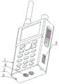
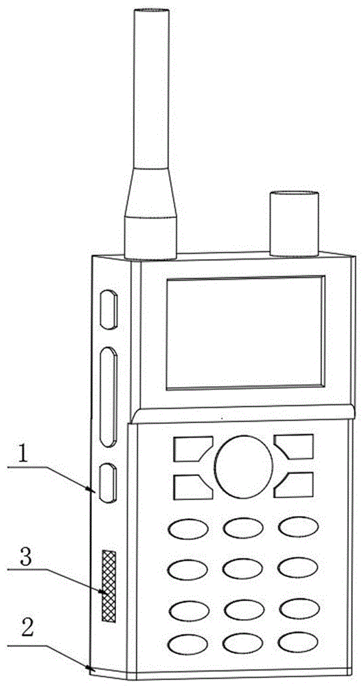
图1为本发明提供的整体结构示意图;Fig. 1 is the overall structure schematic diagram provided by the present invention;
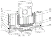
图2为本发明提供的仰视立体图;Fig. 2 is a bottom perspective view provided by the present invention;
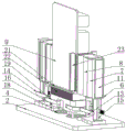
图3为本发明提供的俯视剖视图;Fig. 3 is a top sectional view provided by the present invention;
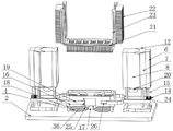
图4为本发明提供的底座立体图;Figure 4 is a perspective view of the base provided by the present invention;
图5为本发明提供的连接壳体立体图;Fig. 5 is a perspective view of the connection housing provided by the present invention;
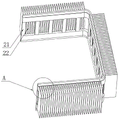
图6为本发明提供的散热片立体图;Figure 6 is a perspective view of the heat sink provided by the present invention;
图7为本发明提供的导热片立体图;Fig. 7 is a perspective view of the heat conducting sheet provided by the present invention;
图8为本发明提供的散热孔导板立体图;Fig. 8 is a perspective view of the heat dissipation hole guide plate provided by the present invention;
图9为本发明提供的底部壳体剖视图;Fig. 9 is a sectional view of the bottom shell provided by the present invention;
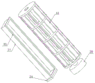
图10为本发明提供的复合型散热组件剖视图;Fig. 10 is a cross-sectional view of the composite heat dissipation assembly provided by the present invention;
图11为本发明提供的贯流风叶立体图;Fig. 11 is a perspective view of the cross-flow fan blade provided by the present invention;
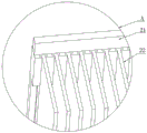
图12为本发明提供的图7中A处结构放大图。Fig. 12 is an enlarged view of the structure at A in Fig. 7 provided by the present invention.
图中:1、对讲机壳体;2、底座;3、侧边散热网;4、底部散热网;5、连接块;6、集尘壳;7、弧形挡板;8、连接壳体;9、元器件;10、贯流风叶;11、集尘袋;12、盖板;13、支撑块;14、齿板;15、连接杆;16、底部壳体;17、第一电机;18、支撑杆;19、连接架;20、第二电机;21、导热片;22、散热片;23、限位板;24、齿轮;25、连接板;26、侧滑槽;27、轴槽;28、连接轴;29、传动轴;30、散热扇叶;31、第三电机;32、滑块;33、支撑框;34、卡板;35、传动杆;36、卡块;37、散热孔导板。In the figure: 1. Walkie-talkie shell; 2. Base; 3. Side heat dissipation net; 4. Bottom heat dissipation net; 5. Connection block; 6. Dust collection case; 7. Curved baffle; 9. Components; 10. Cross-flow fan blade; 11. Dust bag; 12. Cover plate; 13. Support block; 14. Tooth plate; 15. Connecting rod; 16. Bottom shell; 17. First motor; 18 , support rod; 19, connecting frame; 20, second motor; 21, heat conducting sheet; 22, heat sink; 23, limit plate; 24, gear; 25, connecting plate; 26, side chute; 27, shaft groove ; 28, connecting shaft; 29, transmission shaft; 30, heat dissipation fan blade; 31, the third motor; 32, slider; 33, support frame; 34, clamping plate; 35, transmission rod; Thermal hole guide.
具体实施方式Detailed ways
以下由特定的具体实施例说明本发明的实施方式,熟悉此技术的人士可由本说明书所揭露的内容轻易地了解本发明的其他优点及功效,显然,所描述的实施例是本发明一部分实施例,而不是全部的实施例。基于本发明中的实施例,本领域普通技术人员在没有做出创造性劳动前提下所获得的所有其他实施例,都属于本发明保护的范围。The implementation mode of the present invention is illustrated by specific specific examples below, and those who are familiar with this technology can easily understand other advantages and effects of the present invention from the contents disclosed in this description. Obviously, the described embodiments are a part of the present invention. , but not all examples. Based on the embodiments of the present invention, all other embodiments obtained by persons of ordinary skill in the art without making creative efforts belong to the protection scope of the present invention.
参照附图1-12,本发明提供的一种无线对讲机的散热壳体的散热结构,包括对讲机壳体1,所述对讲机壳体1内部固定设有元器件9,所述元器件9外侧设有导热片21,所述导热片21外侧卡接有多个散热片22,所述对讲机壳体1内部设有复合型散热机构和底部散热机构;Referring to accompanying drawings 1-12, the heat dissipation structure of the heat dissipation housing of a wireless walkie-talkie provided by the present invention includes a walkie-
所述复合型散热机构包括两个复合型散热组件,所述散热组件包括连接壳体8,所述连接壳体8一侧与散热片22相接触,所述连接壳体8内部设有贯流风叶10,所述贯流风叶10两端与连接壳体8两侧壁通过轴承连接,所述连接壳体8一侧固定设有第二电机20,所述第二电机20输出端与贯流风叶10固定连接,所述连接壳体8一侧设有集尘壳6,所述集尘壳6顶部和底板均固定连接有盖板12,所述集尘壳6两侧均设有弧形挡板7,所述集尘壳6一侧通过轴承连接有两个传动轴29,两个所述传动轴29分别贯穿两个所述弧形挡板7并与两个所述弧形挡板7固定连接,两个所述传动轴29外部均固定连接有齿轮24,所述集尘壳6内部设有集尘袋11,所述集尘袋11一侧固定连接有支撑框33,所述支撑框33底部固定连接有卡板34,所述卡板34贯穿集尘壳6底部,两个所述齿轮24一侧均啮合连接有齿板14,两个所述齿板14一侧固定连接有连接架19,所述弧形挡板7与两个所述盖板12相接触;The composite heat dissipation mechanism includes two composite heat dissipation assemblies, the heat dissipation assembly includes a
本实施方案中,第二电机20启动并带动贯流风叶10转动,贯流风叶10转动并将侧边的散热片22散发的热量吸收,由于两个弧形挡板7处于闭合状态,使热风无法吹入集尘壳6内部,热风从集尘壳6两侧吹出,并通过侧边散热网3排出热量;In this embodiment, the
其中,为了实现底部散热的目的,本装置采用如下技术方案实现的:所述底部散热机构包括底部壳体16,所述底部壳体16一侧与散热片22相接触,所述底部壳体16另一侧固定连接有四个支撑杆18,四个所述支撑杆18另一端固定连接有底座2,所述底部壳体16内部固定设有两个第三电机31,两个所述第三电机31输出端均固定连接有传动杆35,两个所述传动杆35另一端均固定连接有散热扇叶30,所述底部壳体16一侧开设有两个散热孔导板37,所述底部壳体16内部固定设有两个支撑架,两个所述传动杆35一端分别与两个所述支撑架通过轴承连接,启动第三电机31,第三电机31启动并带动传动杆35转动,传动杆35转动并带动散热扇叶30转动,使散热扇叶30转动并将散热片22上的热量吸收并通过散热孔导板37和底部散热网4排出;Among them, in order to realize the purpose of heat dissipation at the bottom, the device adopts the following technical solution: the bottom heat dissipation mechanism includes a bottom shell 16, one side of the bottom shell 16 is in contact with the heat sink 22, and the bottom shell 16 The other side is fixedly connected with four support rods 18, and the other ends of the four support rods 18 are fixedly connected with the base 2, and the inside of the bottom housing 16 is fixedly provided with two third motors 31, and the two third The output ends of the motor 31 are fixedly connected with transmission rods 35, and the other ends of the two transmission rods 35 are fixedly connected with heat dissipation fan blades 30, and two heat dissipation hole guide plates 37 are provided on one side of the bottom shell 16, and the bottom Two support frames are fixed inside the housing 16, and one end of the two transmission rods 35 is respectively connected with the two support frames through bearings, and the third motor 31 is started, and the third motor 31 starts and drives the transmission rod 35 to rotate, The transmission rod 35 rotates and drives the heat dissipation fan blade 30 to rotate, so that the heat dissipation fan blade 30 rotates and absorbs the heat on the heat dissipation fin 22 and discharges it through the heat dissipation hole guide plate 37 and the bottom heat dissipation net 4;
其中,为了实现除尘的目的,本装置采用如下技术方案实现的:所述连接架19内侧固定设有两个滑块32,两个所述滑块32一侧均设有侧滑槽26,两个所述侧滑槽26开设于底部壳体16侧壁,两个所述滑块32分别在两个所述侧滑槽26内部滑动,所述连接架19一侧固定连接有卡块36,所述卡块36一侧固定连接有连接轴28,所述连接轴28一侧设有连接板25,所述连接板25一侧开设有轴槽27,所述连接轴28在轴槽27内部滑动,所述底部壳体16一侧设有第一电机17,所述第一电机17与底座2固定连接,所述第一电机17输出端与连接板25固定连接,启动第一电机17,第一电机17启动并带动连接板25转动,连接板25转动并带动两个连接轴28移动,使两个连接轴28移动并推动两个连接架19移动,使连接架19移动并推动齿板14移动,使齿板14推动齿轮24转动,齿轮24转动并带动传动轴29转动,使传动轴29带动轴槽27转动,从而使集尘壳6一侧的两个弧形挡板7展开,同时展开的弧形挡板7将集尘壳6两侧堵住,此时再次启动第三电机31,使第三电机31带动传动杆35反转,传动杆35带动散热扇叶30反转,使散热扇叶30对对讲机壳体1内部的散热片22和元器件9进行吹风,使其内的灰尘被扬起,与此同时,第二电机20继续带动贯流风叶10转动,贯流风叶10将热量以及灰尘一起吸入,此时灰尘会进入集尘壳6内部,通过集尘壳6内的集尘袋11对灰尘进行过滤,使灰尘留在集尘袋11内;Wherein, in order to realize the purpose of dust removal, the device adopts the following technical scheme to realize: the inner side of the connecting
其中,为了实现固定的目的,本装置采用如下技术方案实现的:所述盖板12和连接壳体8一侧均固定连接有支撑块13,所述支撑块13另一侧与底座2固定连接,支撑块13将盖板12和连接壳体8与底座2固定,方便一起拆除;Among them, in order to achieve the purpose of fixing, the device adopts the following technical scheme: the
其中,为了实现清理灰尘的目的,本装置采用如下技术方案实现的:所述卡板34一侧固定连接有连接杆15,所述连接杆15一侧固定连接有连接块5,所述连接块5贯穿底座2,所述连接块5与底座2通过螺丝固定,将连接块5与底座2的固定解除,将连接块5拔出,通过连接块5将连接杆15和卡板34拉出,卡板34带动支撑框33和集尘袋11移出,方便清理灰尘;Wherein, in order to achieve the purpose of cleaning dust, the device is realized by adopting the following technical scheme: one side of the
其中,为了实现散热的目的,本装置采用如下技术方案实现的:所述底座2一侧嵌设有两个底部散热网4,所述对讲机壳体1两侧均嵌设有侧边散热网3,底部散热网4和侧边散热网3方便散热;Among them, in order to achieve the purpose of heat dissipation, the device adopts the following technical scheme: two
其中,为了实现限位的目的,本装置采用如下技术方案实现的:所述导热片21两侧均设有两个限位板23,所述导热片21与限位板23相扣合,所述限位板23与对讲机壳体1固定连接,限位板23将导热片21限位;Among them, in order to achieve the purpose of limiting, this device adopts the following technical solution: two limiting
本发明还提供一种无线对讲机的散热壳体,包含上述任一项的散热结构。The present invention also provides a heat dissipation housing of a wireless walkie-talkie, comprising any one of the above heat dissipation structures.
本发明的使用过程如下:在使用本发明时,将散热片22卡入导热片21上,并将其推入对讲机壳体1内部,同时复合散热组机构也一并进入对讲机壳体1内部,将底座2与对讲机壳体1接触并固定,导热片21和散热片22将元器件9散发的热量进行吸收,当散热时,启动第三电机31,第三电机31启动并带动传动杆35转动,传动杆35转动并带动散热扇叶30转动,使散热扇叶30转动并将散热片22上的热量吸收并通过散热孔导板37和底部散热网4排出,同时第二电机20启动并带动贯流风叶10转动,贯流风叶10转动并将侧边的散热片22散发的热量吸收,由于两个弧形挡板7处于闭合状态,使热风无法吹入集尘壳6内部,热风从集尘壳6两侧吹出,并通过侧边散热网3排出热量,需要除尘时,先停止散热,先启动第一电机17,第一电机17启动并带动连接板25转动,连接板25转动并带动两个连接轴28移动,使两个连接轴28移动并推动两个连接架19移动,使连接架19移动并推动齿板14移动,使齿板14推动齿轮24转动,齿轮24转动并带动传动轴29转动,使传动轴29带动轴槽27转动,从而使集尘壳6一侧的两个弧形挡板7展开,同时展开的弧形挡板7将集尘壳6两侧堵住,此时再次启动第三电机31,使第三电机31带动传动杆35反转,传动杆35带动散热扇叶30反转,使散热扇叶30对对讲机壳体1内部的散热片22和元器件9进行吹风,使其内的灰尘被扬起,与此同时,第二电机20继续带动贯流风叶10转动,贯流风叶10将热量以及灰尘一起吸入,此时灰尘会进入集尘壳6内部,通过集尘壳6内的集尘袋11对灰尘进行过滤,使灰尘留在集尘袋11内,同时热量继续通过集尘壳6排出,待除尘完毕后,再次控制两个弧形挡板7闭合,当灰尘需要清理时,将连接块5与底座2的固定解除,将连接块5拔出,通过连接块5将连接杆15和卡板34拉出,卡板34带动支撑框33和集尘袋11移出,方便清理灰尘。The application process of the present invention is as follows: when using the present invention, snap the
以上所述,仅是本发明的较佳实施例,任何熟悉本领域的技术人员均可能利用上述阐述的技术方案对本发明加以修改或将其修改为等同的技术方案。因此,依据本发明的技术方案所进行的任何简单修改或等同置换,尽属于本发明要求保护的范围。The above descriptions are only preferred embodiments of the present invention, and any person skilled in the art may use the above-mentioned technical solutions to modify the present invention or modify it into an equivalent technical solution. Therefore, any simple modification or equivalent replacement made according to the technical solution of the present invention falls within the protection scope of the present invention.
Claims (10)
Priority Applications (1)
| Application Number | Priority Date | Filing Date | Title |
|---|---|---|---|
| CN202310017153.6A CN115802192B (en) | 2023-01-06 | 2023-01-06 | Heat dissipation shell and heat dissipation structure of a wireless walkie-talkie |
Applications Claiming Priority (1)
| Application Number | Priority Date | Filing Date | Title |
|---|---|---|---|
| CN202310017153.6A CN115802192B (en) | 2023-01-06 | 2023-01-06 | Heat dissipation shell and heat dissipation structure of a wireless walkie-talkie |
Publications (2)
| Publication Number | Publication Date |
|---|---|
| CN115802192A true CN115802192A (en) | 2023-03-14 |
| CN115802192B CN115802192B (en) | 2023-04-14 |
Family
ID=85428688
Family Applications (1)
| Application Number | Title | Priority Date | Filing Date |
|---|---|---|---|
| CN202310017153.6A Active CN115802192B (en) | 2023-01-06 | 2023-01-06 | Heat dissipation shell and heat dissipation structure of a wireless walkie-talkie |
Country Status (1)
| Country | Link |
|---|---|
| CN (1) | CN115802192B (en) |
Cited By (3)
| Publication number | Priority date | Publication date | Assignee | Title |
|---|---|---|---|---|
| CN116679808A (en) * | 2023-06-20 | 2023-09-01 | 苏州市凌臣采集计算机有限公司 | Small-sized industrial personal computer convenient for heat dissipation |
| CN118311885A (en) * | 2024-06-11 | 2024-07-09 | 福建宝锋电子有限公司 | Building intercom control system based on Internet of things |
| CN120185632A (en) * | 2025-05-23 | 2025-06-20 | 福建宝锋电子有限公司 | A portable multifunctional intercom |
Citations (6)
| Publication number | Priority date | Publication date | Assignee | Title |
|---|---|---|---|---|
| JP2018069155A (en) * | 2016-10-28 | 2018-05-10 | 株式会社富士通ゼネラル | Suction unit and air cleaner |
| CN208570585U (en) * | 2018-08-30 | 2019-03-01 | 赵灵豆 | A kind of electrified radiator of semiconductor devices |
| CN209731922U (en) * | 2019-03-05 | 2019-12-03 | 浙江机电职业技术学院 | A dust-proof and heat-dissipating device for an electrical control box |
| CN111326960A (en) * | 2018-12-13 | 2020-06-23 | 天津市富源电气设备有限公司 | Self-cleaning high-low voltage switch cabinet |
| CN217523035U (en) * | 2022-02-11 | 2022-09-30 | 湖南警安工程有限公司 | Automatic control device with negative pressure dust collection and heat dissipation functions |
| CN115425791A (en) * | 2022-09-06 | 2022-12-02 | 江苏理工学院 | Efficient dustproof heat dissipation motor and dustproof heat dissipation method thereof |
-
2023
- 2023-01-06 CN CN202310017153.6A patent/CN115802192B/en active Active
Patent Citations (6)
| Publication number | Priority date | Publication date | Assignee | Title |
|---|---|---|---|---|
| JP2018069155A (en) * | 2016-10-28 | 2018-05-10 | 株式会社富士通ゼネラル | Suction unit and air cleaner |
| CN208570585U (en) * | 2018-08-30 | 2019-03-01 | 赵灵豆 | A kind of electrified radiator of semiconductor devices |
| CN111326960A (en) * | 2018-12-13 | 2020-06-23 | 天津市富源电气设备有限公司 | Self-cleaning high-low voltage switch cabinet |
| CN209731922U (en) * | 2019-03-05 | 2019-12-03 | 浙江机电职业技术学院 | A dust-proof and heat-dissipating device for an electrical control box |
| CN217523035U (en) * | 2022-02-11 | 2022-09-30 | 湖南警安工程有限公司 | Automatic control device with negative pressure dust collection and heat dissipation functions |
| CN115425791A (en) * | 2022-09-06 | 2022-12-02 | 江苏理工学院 | Efficient dustproof heat dissipation motor and dustproof heat dissipation method thereof |
Cited By (5)
| Publication number | Priority date | Publication date | Assignee | Title |
|---|---|---|---|---|
| CN116679808A (en) * | 2023-06-20 | 2023-09-01 | 苏州市凌臣采集计算机有限公司 | Small-sized industrial personal computer convenient for heat dissipation |
| CN116679808B (en) * | 2023-06-20 | 2023-12-01 | 苏州市凌臣采集计算机有限公司 | Small-sized industrial personal computer convenient for heat dissipation |
| CN118311885A (en) * | 2024-06-11 | 2024-07-09 | 福建宝锋电子有限公司 | Building intercom control system based on Internet of things |
| CN120185632A (en) * | 2025-05-23 | 2025-06-20 | 福建宝锋电子有限公司 | A portable multifunctional intercom |
| CN120185632B (en) * | 2025-05-23 | 2025-07-11 | 福建宝锋电子有限公司 | Portable multifunctional interphone |
Also Published As
| Publication number | Publication date |
|---|---|
| CN115802192B (en) | 2023-04-14 |
Similar Documents
| Publication | Publication Date | Title |
|---|---|---|
| CN115802192B (en) | Heat dissipation shell and heat dissipation structure of a wireless walkie-talkie | |
| CN212516831U (en) | High-efficient heat abstractor that autotransformer used | |
| CN210015421U (en) | Novel electronic radiator | |
| CN118432401A (en) | A high efficiency heat dissipation power adapter | |
| CN214336487U (en) | A housing for heat dissipation of transformers | |
| CN112152389A (en) | A motor with good heat dissipation | |
| CN113207248B (en) | Converter box body assembly | |
| CN114744806A (en) | Lightweight high-strength motor base | |
| CN222735598U (en) | Low voltage switchgear | |
| CN114286569A (en) | A dust protected gateway shell subassembly for industry internet | |
| CN219535816U (en) | Permanent magnet servo motor with built-in heat dissipation air duct | |
| CN114530975B (en) | A medical miniature brushless motor | |
| CN216462343U (en) | Heat dissipation device applied to desk type reflow soldering machine | |
| CN221226863U (en) | High-voltage distribution cabinet heat dissipation mechanism convenient to maintain | |
| CN214544141U (en) | Novel energy storage inverter | |
| CN113990710B (en) | Relay applied to solar device | |
| CN211529107U (en) | Computer heat abstractor | |
| CN115765321A (en) | A self-circulating cooling motor | |
| CN115835561A (en) | A Production Network Cabinet Convenient for Maintenance | |
| CN218514738U (en) | Heat radiator for be used for wireless network communication equipment | |
| CN114928194A (en) | Energy-saving three-phase asynchronous motor with higher protection capability | |
| CN221884242U (en) | A data processing server | |
| CN224222215U (en) | Dust removal and heat dissipation device of network security server | |
| CN223093795U (en) | A core switch with efficient heat dissipation | |
| CN219575308U (en) | Ferrite core with low-loss structure |
Legal Events
| Date | Code | Title | Description |
|---|---|---|---|
| PB01 | Publication | ||
| PB01 | Publication | ||
| SE01 | Entry into force of request for substantive examination | ||
| SE01 | Entry into force of request for substantive examination | ||
| GR01 | Patent grant | ||
| GR01 | Patent grant | ||
| CP03 | Change of name, title or address | ||
| CP03 | Change of name, title or address |
Address after: No. 888, Changfu Village Hall, Xiamei Town, Nan'an City, Quanzhou City, Fujian Province 362300 Patentee after: FUJIAN BAOFENG ELECTRONIC Co.,Ltd. Country or region after: China Address before: 362000 Changfu Industrial Zone, Xiamei Town, Nan'an City, Quanzhou City, Fujian Province Patentee before: FUJIAN BAOFENG ELECTRONIC Co.,Ltd. Country or region before: China |