CN115787913A - Connecting structure for ceiling keel - Google Patents
Connecting structure for ceiling keel Download PDFInfo
- Publication number
- CN115787913A CN115787913A CN202211409406.6A CN202211409406A CN115787913A CN 115787913 A CN115787913 A CN 115787913A CN 202211409406 A CN202211409406 A CN 202211409406A CN 115787913 A CN115787913 A CN 115787913A
- Authority
- CN
- China
- Prior art keywords
- frame
- fixedly connected
- homonymy
- fixed
- wall
- Prior art date
- Legal status (The legal status is an assumption and is not a legal conclusion. Google has not performed a legal analysis and makes no representation as to the accuracy of the status listed.)
- Withdrawn
Links
Images


Landscapes
- Tents Or Canopies (AREA)
Abstract
The invention relates to the field of suspended ceiling keels, in particular to a connecting structure for a suspended ceiling keel. The invention relates to a connecting mechanism for a suspended ceiling keel, which is characterized in that a bearing keel and a covering keel of the suspended ceiling keel are respectively fixed in a fixing frame and a first combined frame and a second combined frame when in use, the bearing keel and the covering keel are connected together, the fixing frame is connected with a clamping block on a suspender through a butterfly bolt, the first combined frame and the second combined frame are connected together through a positioning mechanism, tools are not needed during connection, the required connection time is short, the load borne by arms and necks of workers is reduced, and the working efficiency of the workers is improved.
Description
Technical Field
The invention relates to the field of ceiling keels, in particular to a connecting structure for a ceiling keel.
Background
The keels are of various types and can be divided into wood keels, light steel keels, aluminum alloy keels, steel keels and the like according to different manufacturing materials. The wall keel is divided according to the using position, and can be divided into a ceiling keel, a vertical wall keel, a floor keel, a hanging keel and the like, and the bearing keel and the cladding keel are arranged according to different decoration construction processes. Ceiling joists, which are frequently seen in ceilings, especially sculpted ceilings, are made of joists framed and then plasterboard coated. The keel is made of light steel and is used as a main material of a suspended ceiling.
When the existing ceiling keel is connected, in order to ensure the stability of the keel frame, the cladding keel is mostly fixed on the bearing keel through a fastener such as a bolt to form the keel frame, and because the ceiling keel is installed above the room, workers mostly stand on a herringbone ladder to lift up hands to operate through tools when installing the ceiling keel, the connection time is long, the load on arms and necks of the workers is large, frequent rest is needed, the working efficiency of the workers is reduced, a suspension rod for suspending the bearing keel is mostly fixed on a structure for connecting the bearing keel and is not connected with the cladding keel, and a gypsum board is fixed on the cladding keel through screws, so that the load borne by the connecting structure of the cladding keel and the bearing keel is large.
Disclosure of Invention
Aiming at the problems in the prior art, the invention provides a connecting structure for a suspended ceiling keel.
The technical scheme adopted by the invention for solving the technical problems is as follows: the utility model provides a connection structure for furred ceiling fossil fragments, includes fixed frame, the upper end fixedly connected with set casing of fixed frame, the inside of set casing can be dismantled through butterfly bolt and be connected with the fixture block, the upper end fixedly connected with jib of fixture block, the upper end fixedly connected with mounting panel of jib, the mid-mounting of jib has coupling mechanism, coupling mechanism is last to be connected with two first carriage through two first fixed establishment and to be connected with the second carriage through two second fixed establishment, two second extension boards of the equal symmetrical fixedly connected with in upper end middle part of first carriage, two first extension boards of the equal symmetrical fixedly connected with in upper end middle part of second carriage, the first frame that closes of fixedly connected with on the lower extreme outer wall of fixed frame, equal fixedly connected with dog on the outer wall of the front and back of first combination frame, the lower extreme of first combination frame is connected with the second combination frame through positioning mechanism.
The first fixing mechanism comprises a first inserting shaft, the first inserting shaft is connected to two second supporting plates on the same side in a penetrating and sliding mode, first pull plates are arranged at two ends of the first inserting shaft, first clamping grooves are formed in the upper ends of the first pull plates, the upper ends of the first pull plates are sleeved on the outer sides of the ends of the first inserting shaft on the same side through the first clamping grooves formed in the upper ends of the first pull plates, sleeve plates are sleeved on the middle portions of the first pull plates and connected in a sliding mode, the sleeve plates are fixedly connected to the outer walls of the first connecting frames on the same side, first limiting grooves are formed in the inner walls of the front side and the rear side of the sleeve plates, first limiting blocks are fixedly connected to the middle portions of the front side and the rear side of the first pull plates, the first limiting blocks are connected to the inside of the first limiting grooves on the same side in a sliding mode, and the lower ends of the first limiting blocks are fixedly connected to the inner walls of the lower ends of the first limiting grooves through first fixing springs.
The second fixing mechanism comprises a second inserting shaft, the second inserting shaft penetrates through two first support plates which are connected to the same side second connecting frame in a sliding mode, a second pull plate is arranged at the front end of the second inserting shaft, a second clamping groove is formed in the upper end of the second pull plate, the upper end of the second pull plate is sleeved outside the front end of the same side second inserting shaft through the second clamping groove formed in the upper end of the second pull plate, the lower end of the second pull plate is detachably connected to the outer wall of the same side second connecting frame through a fixing pin, a baffle is fixedly connected to the back end of the second inserting shaft, a positioning block is fixedly connected to the front lower end of the baffle, and the positioning block is clamped to the back outer wall of the same side second connecting frame.
Specifically, coupling mechanism includes fixed cover, fixed cover establishes and fixed connection is on the middle part outer wall of jib, the both sides of fixed cover are apart from rotating through the pivot and are connected with first connecting plate, two the lower extreme of first connecting plate all pegs graft between two first extension boards on homonymy second link frame and the cover is established in the first axle middle part outside of inserting of homonymy first fixed establishment, the front and back of fixed cover all rotates through the pivot and is connected with the second connecting plate, two the lower extreme of second connecting plate all pegs graft between two second extension boards on homonymy first link frame and the cover is established in the second axle middle part outside of inserting of homonymy second fixed establishment.
Specifically, the positioning mechanisms all comprise lifting plates, the lifting plates are all in L-shaped structures, the horizontal parts of the lifting plates are inserted at the upper ends of the first combined frames, the vertical parts of the lifting plates are all abutted against the outer walls of the first combined frames, the middle parts of the sides, far away from the first combined frames, of the vertical parts of the lifting plates are all fixedly connected with fixed plates, one sides, far away from the first combined frames, of the fixed plates are all rotatably connected with turntables through movable shafts, the outer walls of the circumferences of the middle parts, on one sides of the turntables, of the middle parts are all fixedly connected with rotating plates, the parts, close to the first combined frames, of the rotating plates, far away from the turntables on the same side are all fixedly connected with fixed blocks, the cavity has all been seted up to the inside of fixed block, the second spacing groove has all been seted up on the front and back inner wall of cavity, the cavity all runs through and sliding connection has the dop on being close to one side lateral wall of homonymy carousel, one side that the dop extends to the homonymy fixed block all is half spherical structure and joint on the homonymy dog, the dop is located the equal fixedly connected with second fixed spring in one side in the place cavity, the equal fixed connection of one end that homonymy dop was kept away from to second fixed spring is on the inner wall of place cavity.
Specifically, the equal fixedly connected with swivel in one side middle part that first combination frame was kept away from to the carousel, the internal diameter of swivel is all bigger than the diameter of homonymy loose axle, the outside of swivel all is gear column structure.
Specifically, the equal fixedly connected with second stopper in dop front and back portion, the equal sliding connection of second stopper is in the inside in homonymy second spacing groove.
Specifically, the rotating plates are connected to one side, away from the first combined frame, of the rotating disc and the stop block on the same side in a sliding mode.
The invention has the beneficial effects that:
(1) The invention relates to a connecting mechanism for a suspended ceiling keel, which is characterized in that a bearing keel and a covering keel of the suspended ceiling keel are respectively fixed in a fixing frame and a first combined frame and a second combined frame when in use, the bearing keel and the covering keel are connected together, the fixing frame is connected with a clamping block on a suspender through a butterfly bolt, the first combined frame and the second combined frame are connected together through a positioning mechanism, tools are not needed during connection, the required connection time is short, the load borne by arms and necks of workers is reduced, and the working efficiency of the workers is improved.
(2) The connecting mechanism is arranged on the suspender, the two first connecting plates of the connecting mechanism are connected with the second connecting frame through the second fixing mechanism, the second connecting frame can be sleeved on the covering keel when the connecting mechanism is used, the covering keel is connected to the suspender through the second connecting plate, the covering keel can be lifted by the suspender, and the load born by the first combined frame, the second combined frame and the fixing frame can be reduced.
(3) The two second connecting plates of the connecting mechanism are both connected with the first connecting frame through the first fixing mechanism, and the first connecting frame is sleeved on the bearing keel when the connecting mechanism is used, so that the hanger rod can assist the fixture block to hang the part of the fixing frame connected with the bearing keel, and the load born by the fixture block and the fixing shell can be reduced.
Drawings
The invention is further illustrated with reference to the following figures and examples.
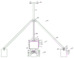
FIG. 1 is a schematic diagram of a front external structure provided by the present invention;
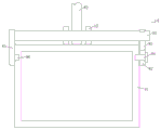
FIG. 2 is a schematic side sectional view of the present invention;
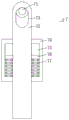
FIG. 3 is a front sectional structural view of a first fixing mechanism provided by the present invention;
FIG. 4 is a schematic side sectional view of a first fixing mechanism provided in the present invention;
FIG. 5 is a schematic sectional view of a second fixing mechanism provided by the present invention on a connecting frame;
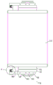
FIG. 6 is a schematic view of a top-down cut-away structure of the positioning mechanism provided by the present invention;
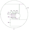
fig. 7 is an enlarged view of the area a in fig. 6.
In the figure: 1. a fixing frame; 2. a stationary housing; 3. a butterfly bolt; 4. a clamping block; 5. a boom; 6. a connecting mechanism; 61. fixing a sleeve; 62. a first connecting plate; 63. a second connecting plate; 7. a first fixing mechanism; 71. a first insert shaft; 72. a first pulling plate; 73. a first card slot; 74. sheathing; 75. a first limit groove; 76. a first stopper; 77. a first fixed spring; 8. a second fixing mechanism; 81. a second shaft; 82. a second pulling plate; 83. a second card slot; 84. a fixing pin; 85. a baffle plate; 86. positioning blocks; 9. a positioning mechanism; 91. a hanger plate; 92. a fixing plate; 93. a movable shaft; 94. a turntable; 95. rotating the ring; 96. rotating the plate; 97. a fixed block; 98. a cavity; 99. a second limit groove; 910. clamping a head; 911. a second limiting block; 912. a second fixed spring; 10. mounting a plate; 11. a first connection frame; 12. a first support plate; 13. a second support plate; 14. a first combination frame; 15. a second combination frame; 16. a stopper; 17. a second connection frame.
Detailed Description
In order to make the technical means, the creation characteristics, the achievement purposes and the effects of the invention easy to understand, the invention is further described with the specific embodiments.
As shown in fig. 1 to 7, the connection structure for the ceiling keel according to the invention comprises a fixed frame 1, wherein a fixed shell 2 is fixedly connected to the upper end of the fixed frame 1, a fixture block 4 is detachably connected to the inside of the fixed shell 2 through a butterfly bolt 3, a suspension rod 5 is fixedly connected to the upper end of the fixture block 4, a mounting plate 10 is fixedly connected to the upper end of the suspension rod 5, a connection mechanism 6 is installed in the middle of the suspension rod 5, the connection mechanism 6 is connected with two first connection frames 11 through two first fixing mechanisms 7 and is connected with a second connection frame 17 through two second fixing mechanisms 8, the middle part of the upper end of the first connection frame 11 is symmetrically and fixedly connected with two second support plates 13, the middle part of the upper end of the second connection frame 17 is symmetrically and fixedly connected with two first support plates 12, a first combination frame 14 is fixedly connected to the outer wall of the lower end of the fixed frame 1, the front and rear outer walls of the first combination frame 14 are fixedly connected with stop blocks 16, the lower end of the first combination frame 14 is connected to a second combination frame 15 through a positioning mechanism 9, and the ceiling keel surface is clamped by the first combination frame 14 and the ceiling keel surface.
Specifically, first fixed establishment 7 all includes first axle 71 of inserting, first axle 71 of inserting all runs through and sliding connection is on two second extension boards 13 of homonymy, the both ends of first axle 71 of inserting all are equipped with first arm-tie 72, first draw-in groove 73 has all been seted up to the upper end of first arm-tie 72, the upper end of first arm-tie 72 all overlaps through the first draw-in groove 73 cover of seting up and establishes the tip outside of the first axle 71 of inserting of homonymy, the middle part of first arm-tie 72 all overlaps and sliding connection has sleeve plate 74, the equal fixed connection of sleeve plate 74 is on the outer wall of the first linking frame 11 of homonymy, first spacing groove 75 has all been seted up on the front and back side inner wall of sleeve plate 74, the equal fixed connection in front and back side middle part of first arm-tie 72 has first stopper 76, the equal sliding connection of first stopper 76 is in the inside of first spacing groove 75, the lower extreme of first stopper 76 all is through first fixed spring 77 fixed connection on the lower extreme inner wall of first spacing groove 75 of homonymy, be convenient for connect first linking mechanism 6 on homonymy.
Specifically, the second fixing mechanism 8 includes a second inserting shaft 81, the second inserting shaft 81 penetrates through and is slidably connected to the two first supporting plates 12 on the same-side second connecting frame 17, the front end of the second inserting shaft 81 is provided with a second pulling plate 82, the upper end of the second pulling plate 82 is provided with a second clamping groove 83, the upper end of the second pulling plate 82 is sleeved on the outer side of the front end of the same-side second inserting shaft 81 through the second clamping groove 83, the lower end of the second pulling plate 82 is detachably connected to the outer wall of the same-side second connecting frame 17 through a fixing pin 84, a baffle 85 is fixedly connected to one end of the back of the second inserting shaft 81, a positioning block 86 is fixedly connected to the lower end of the front of the baffle 85, the positioning block 86 is clamped in the back of the outer wall of the same-side second connecting frame 17, the second connecting frame 17 can be connected to the connecting mechanism 6, and the hanging rod 5 can hang the keel.
Specifically, coupling mechanism 6 is including fixed cover 61, fixed cover 61 cover is established and fixed connection is on the middle part outer wall of jib 5, the both sides of fixed cover 61 are apart from rotating through the pivot and being connected with first connecting plate 62, two between two first branch boards 12 on homonymy second link frame 17 are all pegged graft to first connecting plate 62's lower extreme and the cover is established in the first axle 71 middle part outside of inserting of homonymy first fixed establishment 7, the front and back portion of fixed cover 61 all rotates through the pivot and is connected with second connecting plate 63, two the lower extreme of second connecting plate 63 is all pegged graft between two second branch boards 13 on homonymy first link frame 11 and the cover is established in the second axle 81 middle part outside of inserting of homonymy second fixed establishment 8, and the jib 5 of being convenient for hangs the department of meeting that bears fossil fragments and the cladding fossil fragments of furred ceiling fossil fragments.
Specifically, the positioning mechanisms 9 each include a hanging plate 91, the hanging plates 91 are each of an L-shaped structure, and the horizontal portion thereof is inserted into the upper end of the first assembly frame 14, the vertical portions of the hanging plates 91 are each abutted against the outer wall of the first assembly frame 14, the middle portions of the vertical portions of the hanging plates 91, which are away from the first assembly frame 14, are each fixedly connected with a fixing plate 92, the sides of the fixing plates 92, which are away from the first assembly frame 14, are each rotatably connected with a rotating plate 94 through a movable shaft 93, the middle portions of the rotating plates 94, which are away from the first assembly frame 14, are each fixedly connected with a rotating ring 95, the inner diameters of the rotating rings 95 are each larger than the diameter of the movable shafts 93 at the same side, the outer sides of the rotating rings 95 are each of a gear-shaped structure, the outer walls of the circumferences of the middle portions of one side of the rotating plates 94 are each fixedly connected with a rotating plate 96, the rotating plates 96 are each slidably connected to the sides of the rotating plates 94 and 16 at the same side, which are away from the first assembly frame 14, the parts of the rotating plate 96, which are close to the first combined frame 14 and far away from the same-side rotating disc 94, are fixedly connected with fixed blocks 97, cavities 98 are formed in the fixed blocks 97, second limiting grooves 99 are formed in the inner walls of the front and rear parts of the cavities 98, clamping heads 910 penetrate through and are slidably connected to the side wall of one side, close to the same-side rotating disc 94, of each cavity 98, one sides, extending to the same-side fixed blocks 97, of the clamping heads 910 are of a hemispherical structure and are clamped on the same-side stop blocks 16, second fixing springs 912 are fixedly connected to one sides, located in the cavities 98, of the clamping heads 910, one ends, far away from the same-side clamping heads 910, of the second fixing springs 912 are fixedly connected to the inner wall of the cavities 98, second limiting blocks 911 are fixedly connected to the front and rear parts of the clamping heads 910, the second limiting blocks are slidably connected to the insides of the same-side second limiting grooves 99, and when the first combined frame 14 and the second combined frame 15 are connected together during use, the covering keel and the bearing keel are connected together, so that the ceiling keel is convenient to combine.
When the ceiling hanging device is used, the mounting plate 10 is fixed on the top of an indoor wall through an expansion bolt, the hanging rod 5 is fixed, the fixing frame 1 and the first connecting frame 11 are sleeved and fixed on the bearing keel, meanwhile, the fixture block 4 is clamped inside the fixing shell 2, the fixture block 4 is fixed inside the fixing shell 2 through the butterfly bolt 3, the bearing keel is hung, then, the second connecting frame 17 is sleeved on the cladding keel, the upper end of the cladding keel is clamped inside the first combination frame 14, the second combination frame 15 is sleeved at the lower end of the cladding keel, the second combination frame 15 is slid, the upper ends of two hanging plates 91 on the second combination frame 15 are clamped at the upper end of the fixing frame 1, the fixing block 97 is slid on the stop block 16 through the rotating ring 95, the fixing block 94 is rotated to enable the fixing block 97 to slide on the stop block 16, in the process, the clamping head 910 is gradually extruded into the cavity 98 and continuously extrudes the second fixing spring 912, when the clamping head 910 is opposite to the hole grooves on the stop block 16, the clamping head 910 is clamped in the hole grooves on the second fixing spring 912, the position of the second fixing block 16, the cladding plate 96 is pulled, the hanging plate is clamped with the second combination frame 14, and the bearing keel is clamped together; then, the first connecting frame 11 is slid and the second connecting plate 63 is rotated, the lower end of the second connecting plate 63 is inserted between the two second support plates 13 on the first connecting frame 11, one of the first pulling plates 72 is lifted, the first pulling plate 72 continuously stretches the first fixing spring 77 through the first limiting block 76, the upper end of the first clamping groove 73 on the first pulling plate 72 is aligned with the holes on the two second support plates 13, the first inserting shaft 71 penetrates through the first clamping groove 73 on the first pulling plate 72 and the holes on the two second support plates 13 and the second connecting plate 63, the other first pulling plate 72 can be lifted, the first inserting shaft 71 is inserted into the first clamping groove 73 on the first pulling plate 72, when the depressions at the two ends of the first inserting shaft 71 are aligned with the first clamping grooves 73 on the two first pulling plates 72, the two first pulling plates 72 move downwards under the pulling of the first fixing spring 77 and are clamped inside the depressions on the first inserting shaft 71, the positions of the first inserting shaft 71 are fixed, the lower ends of the first pulling plates 63 are connected to the first connecting plate 11, and the keel can be supported by the keel 11; then, the second connection frame 17 is slid and the first connection plate 62 is rotated, the lower end of the first connection plate 62 is inserted between the two first support plates 12 on the second connection frame 17, the second insertion shaft 81 penetrates through the holes in the two first support plates 12 and the first connection plate 62 until the baffle 85 abuts against the second connection frame 17, a second pull plate 82 is sleeved at a recessed position of one end, far away from the baffle 85, of the second insertion shaft 81, the second pull plate 82 is fixed on the second connection frame 17 through a fixing pin 84, at this moment, connection of the ceiling keel is completed, and the ceiling keel is fixed at the indoor upper end.
The foregoing illustrates and describes the principles, general features, and advantages of the present invention. It will be understood by those skilled in the art that the present invention is not limited to the embodiments described above, which are intended to illustrate the principles of the invention, but that various changes and modifications may be made without departing from the spirit and scope of the invention, and such changes and modifications are intended to be within the scope of the invention as claimed. The scope of the invention is defined by the appended claims and equivalents thereof.
Claims (8)
1. The utility model provides a connection structure for furred ceiling fossil fragments, includes fixed frame (1), its characterized in that, upper end fixedly connected with set casing (2) of fixed frame (1), the inside of set casing (2) can be dismantled through butterfly bolt (3) and be connected with fixture block (4), upper end fixedly connected with jib (5) of fixture block (4), upper end fixedly connected with mounting panel (10) of jib (5), the mid-mounting of jib (5) has coupling mechanism (6), be connected with two first carriage (11) and be connected with second carriage (17) through two second fixed establishment (8) on coupling mechanism (6), the equal symmetrical two second extension boards (13) of upper end middle part of first carriage (11), the equal symmetrical two first extension boards (12) of upper end middle part of second carriage (17), fixedly connected with first combination frame (14) on the lower extreme outer wall of fixed frame (1), equal fixedly connected with on the front and back outer wall of first combination frame (14) is 16), the second combination frame (9) through second positioning mechanism (15).
2. The connecting structure for a ceiling runner according to claim 1, wherein: first fixed establishment (7) all include first insert axle (71), first insert axle (71) all run through and sliding connection is on two second extension boards (13) of homonymy, the both ends of first insert axle (71) all are equipped with first arm-tie (72), first draw-in groove (73) have all been seted up to the upper end of first arm-tie (72), the tip outside at the first insert axle (71) of homonymy is all established through first draw-in groove (73) cover seted up to the upper end of first arm-tie (72), the middle part of first arm-tie (72) is all overlapped and is established and sliding connection has lagging (74), the equal fixed connection of lagging (74) is on the outer wall of the first link frame of homonymy (11), first spacing groove (75) have all been seted up on the side inner wall around lagging (74), the equal fixedly connected with first stopper (76) in the middle part of the front and back side of first arm-tie (72), the equal sliding connection of first stopper (76) is in the inside of first spacing groove (75), the equal fixed connection of first stopper (76) is in the lower extreme of first stopper (77) the first stopper (75) the first fixed connection on the homonymy.
3. The connecting structure for a ceiling runner according to claim 1, wherein: second fixed establishment (8) all include that the second inserts axle (81), axle (81) is inserted in the second all runs through and sliding connection is on two first extension boards (12) on homonymy second link frame (17) on, the front one end of axle (81) is inserted in the second all is equipped with second arm-tie (82), second draw-in groove (83) have all been seted up to the upper end of second arm-tie (82), the upper end of second arm-tie (82) all cup joints the front one end outside of inserting axle (81) at homonymy second through the second draw-in groove (83) of seting up, the lower extreme of second arm-tie (82) all can dismantle the connection on the outer wall of homonymy second link frame (17) through fixed pin (84), the equal fixedly connected with baffle (85) of back one end of axle (81) is inserted to the second, the equal fixedly connected with locating piece (86) of the front lower extreme of baffle (85), the equal joint of locating piece (86) is in the back outer wall of second link frame (17) homonymy.
4. The connecting structure for a ceiling runner according to claim 1, wherein: coupling mechanism (6) are including fixed cover (61), fixed cover (61) cover is established and fixed connection is on the middle part outer wall of jib (5), the both sides of fixed cover (61) are apart from rotating through the pivot and are connected with first connecting plate (62), two the lower extreme of first connecting plate (62) all pegs graft between two first extension boards (12) on homonymy second link (17) and establish in the first inserted shaft (71) middle part outside of homonymy first fixed establishment (7), the front and back portion of fixed cover (61) all rotates through the pivot and is connected with second connecting plate (63), two the lower extreme of second connecting plate (63) all pegs graft between two second extension boards (13) on homonymy first link (11) and establish in the second inserted shaft (81) middle part outside of homonymy second fixed establishment (8).
5. The connecting structure for a ceiling runner according to claim 1, wherein: the positioning mechanisms (9) comprise lifting plates (91), the lifting plates (91) are of L-shaped structures, the horizontal parts of the lifting plates (91) are inserted into the upper ends of the first combined frames (14), the vertical parts of the lifting plates (91) are abutted to the outer walls of the first combined frames (14), the middle parts of one sides, far away from the first combined frames (14), of the vertical parts of the lifting plates (91) are fixedly connected with fixing plates (92), one sides, far away from the first combined frames (14), of the fixing plates (92) are rotatably connected with rotary tables (94) through movable shafts (93), rotating plates (96) are fixedly connected onto the outer wall of the circumference of the middle part of one side of each rotary table (94), the rotating plates (96) are close to the first combined frames (14) and are fixedly connected with fixing blocks (97) of the parts, far away from the rotary tables (94) on the same side, of the fixing blocks (97) are respectively provided with cavities (98), the inner walls of the front and back parts of the cavities (98) are respectively provided with second limiting grooves (99), the side walls of the cavities (98) are respectively provided with a sliding block (910), one side wall of one side, one side of the fixing blocks (910) extends to one side of the fixing blocks (910), and are respectively connected with a hemispherical spring (910), one end of the second fixing spring (912), which is far away from the clamping head (910) on the same side, is fixedly connected to the inner wall of the cavity (98).
6. The connecting structure for a ceiling runner according to claim 5, wherein: the middle part of one side of the turntable (94) far away from the first combined frame (14) is fixedly connected with a rotating ring (95), the inner diameter of the rotating ring (95) is larger than the diameter of the movable shaft (93) on the same side, and the outer side of the rotating ring (95) is in a gear-shaped structure.
7. The connection structure for the ceiling grid as claimed in claim 5, wherein: the front part and the rear part of the clamping head (910) are fixedly connected with second limiting blocks (911), and the second limiting blocks (911) are connected inside second limiting grooves (99) on the same side in a sliding mode.
8. The connecting structure for a ceiling runner according to claim 5, wherein: the rotating plates (96) are connected with the same side of the rotating disc (94) and the stopper (16) far away from the first combined frame (14) in a sliding way.
Priority Applications (1)
| Application Number | Priority Date | Filing Date | Title |
|---|---|---|---|
| CN202211409406.6A CN115787913A (en) | 2022-11-11 | 2022-11-11 | Connecting structure for ceiling keel |
Applications Claiming Priority (1)
| Application Number | Priority Date | Filing Date | Title |
|---|---|---|---|
| CN202211409406.6A CN115787913A (en) | 2022-11-11 | 2022-11-11 | Connecting structure for ceiling keel |
Publications (1)
| Publication Number | Publication Date |
|---|---|
| CN115787913A true CN115787913A (en) | 2023-03-14 |
Family
ID=85436847
Family Applications (1)
| Application Number | Title | Priority Date | Filing Date |
|---|---|---|---|
| CN202211409406.6A Withdrawn CN115787913A (en) | 2022-11-11 | 2022-11-11 | Connecting structure for ceiling keel |
Country Status (1)
| Country | Link |
|---|---|
| CN (1) | CN115787913A (en) |
Cited By (2)
| Publication number | Priority date | Publication date | Assignee | Title |
|---|---|---|---|---|
| CN119466210A (en) * | 2024-12-26 | 2025-02-18 | 天津中天承邺建筑设计有限公司 | Assembled light steel keel ceiling and installation method thereof |
| CN119466207A (en) * | 2024-12-11 | 2025-02-18 | 广州金霸建材股份有限公司 | A ceiling adjustment structure |
-
2022
- 2022-11-11 CN CN202211409406.6A patent/CN115787913A/en not_active Withdrawn
Cited By (2)
| Publication number | Priority date | Publication date | Assignee | Title |
|---|---|---|---|---|
| CN119466207A (en) * | 2024-12-11 | 2025-02-18 | 广州金霸建材股份有限公司 | A ceiling adjustment structure |
| CN119466210A (en) * | 2024-12-26 | 2025-02-18 | 天津中天承邺建筑设计有限公司 | Assembled light steel keel ceiling and installation method thereof |
Similar Documents
| Publication | Publication Date | Title |
|---|---|---|
| CN113418054B (en) | Fire engineering pipeline installation device and installation method | |
| CN115504364A (en) | A split-type tooling for hoisting curtain wall units | |
| CN105798885A (en) | Building decoration supporting robot based on three-freedom-degree parallel mechanism | |
| CN215290935U (en) | Architectural decoration furred ceiling based on BIM technique | |
| CN213371263U (en) | Novel (window) curtain roman pole mounting structure | |
| CN205276655U (en) | Easy dismouting furred ceiling | |
| CN119062053A (en) | Energy-saving and heat-insulating ceiling quick installation structure and use method | |
| CN116618924B (en) | Be applicable to warm pipeline welding with supplementary butt joint support of pipeline multi-angle | |
| CN219100469U (en) | Suspended ceiling mounting structure is built in room | |
| CN219491449U (en) | Hanging ceiling mounting structure free of hanging rod | |
| CN215106462U (en) | A design structure of super-high ceiling transition layer based on surface layer control | |
| CN2498241Y (en) | Assembled metal ceiling | |
| CN214884774U (en) | Suspended ceiling module of steel structure house | |
| CN211283638U (en) | Sliding hanging basket device on spherical net rack | |
| CN222163827U (en) | A kind of building mechanical and electrical pipeline support and hanger | |
| CN220669008U (en) | Projector hanging bracket | |
| CN1873151B (en) | Tie rod device for building suspended ceiling | |
| CN205296541U (en) | Suspended ceiling installation structure | |
| CN116040463B (en) | A steel structure keel lifting fixture | |
| CN206846496U (en) | A kind of LED panel lamp | |
| CN224162169U (en) | Internal supporting structure of comprehensive pipe rack | |
| CN219887419U (en) | Assembled green energy-saving building external wall board | |
| CN205557932U (en) | Two support connecting elementss of unitized curtain wall | |
| CN222771724U (en) | Support frame of indoor furred ceiling | |
| CN219671821U (en) | Aluminum square tube suspended ceiling structure comprising access hole |
Legal Events
| Date | Code | Title | Description |
|---|---|---|---|
| PB01 | Publication | ||
| PB01 | Publication | ||
| SE01 | Entry into force of request for substantive examination | ||
| SE01 | Entry into force of request for substantive examination | ||
| WW01 | Invention patent application withdrawn after publication |
Application publication date: 20230314 |
|
| WW01 | Invention patent application withdrawn after publication |