CN115740142A - Automatic steel-plastic composite board blank pressing equipment with feeding and adjusting functions - Google Patents
Automatic steel-plastic composite board blank pressing equipment with feeding and adjusting functions Download PDFInfo
- Publication number
- CN115740142A CN115740142A CN202211485426.1A CN202211485426A CN115740142A CN 115740142 A CN115740142 A CN 115740142A CN 202211485426 A CN202211485426 A CN 202211485426A CN 115740142 A CN115740142 A CN 115740142A
- Authority
- CN
- China
- Prior art keywords
- plate
- plastic composite
- steel
- pressure bearing
- edge pressing
- Prior art date
- Legal status (The legal status is an assumption and is not a legal conclusion. Google has not performed a legal analysis and makes no representation as to the accuracy of the status listed.)
- Granted
Links
- 238000003825 pressing Methods 0.000 title claims abstract description 54
- 229920003023 plastic Polymers 0.000 title claims abstract description 51
- 239000004033 plastic Substances 0.000 title claims abstract description 51
- 239000002131 composite material Substances 0.000 title claims abstract description 50
- 230000007246 mechanism Effects 0.000 claims abstract description 18
- 238000004080 punching Methods 0.000 claims description 13
- 239000000463 material Substances 0.000 claims description 8
- 239000011241 protective layer Substances 0.000 claims description 3
- 239000011230 binding agent Substances 0.000 claims 1
- 230000001105 regulatory effect Effects 0.000 claims 1
- 238000001179 sorption measurement Methods 0.000 claims 1
- 241000252254 Catostomidae Species 0.000 abstract description 2
- 238000000034 method Methods 0.000 description 8
- 229910000838 Al alloy Inorganic materials 0.000 description 6
- 239000000956 alloy Substances 0.000 description 4
- 229910000831 Steel Inorganic materials 0.000 description 3
- 230000008569 process Effects 0.000 description 3
- 239000010959 steel Substances 0.000 description 3
- 230000008901 benefit Effects 0.000 description 2
- 238000003754 machining Methods 0.000 description 2
- 238000012986 modification Methods 0.000 description 2
- 230000004048 modification Effects 0.000 description 2
- 230000006978 adaptation Effects 0.000 description 1
- 230000009286 beneficial effect Effects 0.000 description 1
- 230000008859 change Effects 0.000 description 1
- 150000001875 compounds Chemical class 0.000 description 1
- 238000005034 decoration Methods 0.000 description 1
- 230000014509 gene expression Effects 0.000 description 1
- 238000004519 manufacturing process Methods 0.000 description 1
- 230000009467 reduction Effects 0.000 description 1
Images


Landscapes
- Casting Or Compression Moulding Of Plastics Or The Like (AREA)
Abstract
The invention provides an automatic feeding and adjusting edge pressing device for a steel-plastic composite plate, which comprises: a feeding mechanism and a blank holder device; feed mechanism includes: the device comprises a sucker frame, a moving arm, a lifting arm and a rack, wherein a plurality of suckers are arranged at the bottom of the sucker frame; the head end of the movable arm is rotatably provided with a suction disc frame; the lower end of the lifting arm is movably provided with a moving arm; the blank pressing device includes: a main body and a blank holder assembly; the main body is provided with a lifting frame, and a workbench is arranged under the lifting frame; blank pressing subassembly includes: the mounting plate and the bearing plate; the mounting plate is mounted at the bottom of the lifting frame, a stamping plate is arranged at the bottom of the mounting plate, and a stamping surface is arranged on the bottom surface of the stamping plate; the pressure bearing plate is arranged on the workbench, and the upper end surface of the pressure bearing plate is provided with a pressure bearing surface; the moving arm is movably arranged in the direction close to or far away from the bearing plate; the lifting arm is arranged on the frame along the moving direction which is vertical to the moving arm. The invention aims to feed the steel-plastic composite board through the feeding mechanism to carry out edge pressing treatment and azimuth replacement, thereby improving the efficiency and reducing the labor intensity.
Description
Technical Field
The invention relates to the field of steel-plastic composite board processing equipment, in particular to steel-plastic composite board edge pressing equipment capable of automatically feeding and adjusting.
Background
In recent years, aluminum alloy materials used in van trucks are gradually replaced by steel-plastic composite board materials, and compared with the original aluminum alloy materials, the aluminum alloy materials have more obvious advantages. Firstly, the total thickness of the original outer skin and the original inner lining is reduced, and the reduction of the thickness of the car body means that the space in a carriage is enlarged, so that the using space of a vehicle is more flexible when the tray structure is used for transportation. Secondly, the strength of the steel-plastic composite material is stronger than that of aluminum alloy, the aluminum alloy material is light but easy to damage, any collision can damage the aluminum alloy body, and the damage rate of the body can be greatly reduced by using the material of the steel-plastic composite plate.
Wherein, the composite sheet concatenation department is moulded to two adjacent steel adopts connecting plate and rivet fixed connection usually, thereby splice one by one and form structures such as box, in order to let concatenation department obtain basic smooth surface, and do not let connecting plate and rivet protrusion in compound face, need carry out the blank pressing with its limit joint limit department when processing, be about 28mm if form one width, the blank pressing of 1mm is about deeply, the mode that adopts artifical material loading at present carries out the material loading, the adjustment, this kind of mode is not only inefficient relatively, also there is certain potential safety hazard. Moreover, the internal texture of the steel-plastic composite board, especially the edge pressing interface, is more obvious in a stamping mode of a common straight-up stamping mode and a straight-down stamping mode, and therefore a series of problems need to be solved urgently.
Disclosure of Invention
In view of this, the invention aims to provide an automatic feeding and adjusting edge pressing device for a steel-plastic composite board, which feeds the steel-plastic composite board through a feeding mechanism to perform edge pressing treatment and changes the edge pressing direction of the board, so that the processing efficiency of the product is improved at least to a certain extent, and the labor intensity is reduced.
In order to achieve the above purpose, the technical scheme adopted by the invention is as follows:
the invention provides an automatic feeding and adjusting steel-plastic composite board edge pressing device, which comprises: a feeding mechanism and a blank holder device;
the feed mechanism includes: the device comprises a sucker frame, a moving arm, a lifting arm and a rack, wherein a plurality of suckers for adsorbing the upper surface of the steel-plastic composite plate are arranged at the bottom of the sucker frame; the head end of the moving arm is rotatably provided with the suction disc frame around a vertical shaft; the lower end of the lifting arm is movably provided with the moving arm;
the blank pressing device comprises: a main body and a blank holder assembly; the main body is provided with a lifting frame driven by a hydraulic cylinder, and a workbench is arranged under the lifting frame; the blank holder subassembly includes: the mounting plate and the bearing plate; the mounting plate is detachably mounted at the bottom of the lifting frame, a stamping plate is arranged at the bottom of the mounting plate, and a stamping surface is arranged on the bottom surface of the stamping plate; the press plate is detachably arranged on the workbench, the upper end surface of the press plate is provided with a press face, and when the bottom surface of one side of the steel-plastic composite plate moves onto the press face, the press plate moves downwards to perform press edge treatment on the upper end surface of the steel-plastic composite plate through the press face;
the moving arm is movably arranged on the horizontal plane in a direction close to or far away from the bearing plate; the lifting arm is arranged on the rack on a horizontal plane along a moving direction vertical to the moving arm.
In some embodiments, the stamping plate is arranged on the mounting plate in a transverse moving mode, and one side of the stamping surface is provided with a stamping inclined surface; correspondingly, one side of the pressure bearing face is provided with a pressure bearing inclined face, and when the punching face carries out edge pressing treatment on the upper end face of the steel-plastic composite plate, the punching inclined face and the pressure bearing inclined face are matched to enable the punching plate to move towards the side end face of the edge pressing position.
In some embodiments, a step for limiting a side end face at the edge pressing position of the steel-plastic composite plate is arranged at the intersection of the pressure bearing face and the pressure bearing inclined face.
In some embodiments, further comprising: the upper end face of the base plate is detachably arranged at the bottom of the lifting frame, and the lower end face of the base plate is provided with the stamping plate.
In some embodiments, further comprising: the supporting block, the supporting block top detachably installs on the mounting panel, the supporting block lower extreme with the ram plate is connected.
In some embodiments, the clamping device further comprises clamping plates which are oppositely arranged on two sides of the bearing plate, and the clamping plates are detachably arranged on the workbench.
In some embodiments, the bottom of the lifting frame is provided with a dovetail groove.
In some embodiments, two opposite sides of the main body are provided with vertical guide rails for guiding the lifting frame.
In some embodiments, the hydraulic cylinder includes one master cylinder and two side cylinders.
In some embodiments, a protective layer is provided on the stamping surface.
Compared with the prior art, the automatic feeding and adjusting steel-plastic composite board edge pressing equipment provided by the invention has the beneficial effects that: through feed mechanism with steel-plastic composite panel pay-off carry out the blank pressing and handle to and the change to panel blank pressing position, specifically can realize X axle-Y axle-Z epaxial removal and around Z axle rotation come diversified free adjustment with panel, can satisfy multilateral blank pressing on the panel and handle production demand, improved product machining efficiency and reduced intensity of labour.
Compared with the common straight-up and straight-down stamping, the stamping surface applies force to the side end surface of the plate while pressing down, so that on one hand, the influence on the strength of the plate due to cliff type tearing in the pressed boundary of the steel-plastic plate is avoided, on the other hand, the inclined trend on the pressed boundary of the steel-plastic plate is smoothly transited, the stress concentration is greatly reduced, and the strength of the edge pressing interface is greatly improved.
The equipment in the invention brings great convenience to operators, improves the quality and economic benefit of products, and is worthy of being popularized and used in large quantities.
Drawings
In order to more clearly illustrate the technical solutions of the embodiments of the present invention, the drawings that are required to be used in the embodiments will be briefly described below, it should be understood that the following drawings only illustrate some embodiments of the present invention and therefore should not be considered as limiting the scope, and for those skilled in the art, other related drawings can be obtained according to the drawings without inventive efforts.
Fig. 1 is a schematic side view of the embodiment of the invention.
Fig. 2 is a schematic perspective view of the feeding mechanism in fig. 1 according to the present invention.
Fig. 3 is a front view of a half-section structure of the edge pressing device in fig. 1.
FIG. 4 isbase:Sub>A schematic sectional view taken along line A-A of FIG. 3 according to the present invention.
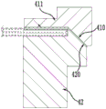
Fig. 5 is a schematic structural view of the press plate and the pressure bearing plate in a pressing state according to the present invention in fig. 4.
The text labels in the figures are represented as: 3. a feeding mechanism; 30. a suction cup holder; 31. a moving arm; 32. a lifting arm; 33. a frame; 4. a blank pressing device; 40. a main body; 400. a hydraulic cylinder; 401. a lifting frame; 402. a work table; 41. mounting a plate; 410. stamping an inclined plane; 411. stamping the plate; 412. a backing plate; 413. a supporting block; 42. a pressure bearing plate; 420. a pressure bearing inclined plane; 421. a clamping plate; 43. a vertical guide rail.
Detailed Description
The present invention will be described in detail below with reference to the accompanying drawings in order to make those skilled in the art better understand the technical solution of the present invention, and the description in this section is only exemplary and illustrative, and should not be construed as limiting the scope of the present invention in any way.
Example one
In an embodiment, referring to fig. 1 to 5, an embodiment of the present invention provides an automatic feeding and adjusting edge pressing apparatus for steel-plastic composite boards, including: a feeding mechanism 3 and a blank pressing device 4;
the feed mechanism 3 includes: the device comprises a suction disc frame 30, a moving arm 31, a lifting arm 32 and a rack 33, wherein the bottom of the suction disc frame 30 is provided with a plurality of suction discs for adsorbing the upper surface of the steel-plastic composite plate, the suction discs can be arranged in a rectangular array and are all adsorbed and loosened through pneumatic control; the suction cup frame 30 is rotatably mounted at the head end of the moving arm 31 around a vertical shaft, specifically, a vertical rotating shaft which is controlled to rotate by a stepping motor is arranged at the head end of the moving arm 31, and the suction cup frame 30 is mounted at the lower end of the rotating shaft, so that the suction cup frame 30 can rotate at least 180 degrees in the horizontal plane; the lower end of the lifting arm 32 is movably provided with the moving arm 31, that is, the lifting arm 32 can be driven by a vertically arranged cylinder, an electric push rod and the like to vertically move the moving arm 31 to adjust the height, and of course, any other mechanism capable of lifting the moving arm 31 can be used;
the edge pressing device 4 includes: a main body 40 and a blank holder assembly; the main body 40 is provided with a lifting frame 401 driven by a hydraulic cylinder 400, namely, the hydraulic cylinder 400 is vertically arranged, the telescopic end of the hydraulic cylinder is downward and is fixedly connected with the lifting frame 401, and a workbench 402 is arranged under the lifting frame 401; the blank pressing subassembly includes: mounting plate 41 and pressure bearing plate 42; the mounting plate 41 is detachably mounted at the bottom of the lifting frame 401 and can be fixedly connected through bolts, a stamping plate 411 is arranged at the bottom of the mounting plate 41, a stamping surface is arranged on the bottom surface of the stamping plate 411, and the length and the width of the stamping surface can be matched with the plate surface to be stamped; the pressure bearing plate 42 is also detachably mounted on the workbench 402, the upper end surface of the pressure bearing plate 42 is provided with a pressure bearing surface for supporting the bottom surface of the steel-plastic composite plate, and when the bottom surface of one side of the steel-plastic composite plate moves onto the pressure bearing surface, the stamping plate 411 moves downwards to perform edge pressing treatment on the upper end surface of the steel-plastic composite plate through the stamping surface;
the moving arm 31 is movably disposed on a horizontal plane in a direction close to or far from the bearing plate 42, that is, a guide rail may be disposed at the upper end of the moving arm 31, the lower end of the lifting arm 32 is engaged with the guide rail, a gear mechanism may be disposed inside the lower end of the lifting arm 32, the moving arm 31 is moved in a direction close to or far from the bearing plate 42 by the engagement of the gear mechanism and a rack on the moving arm 31, and of course, other mechanisms capable of realizing linear reciprocating motion may be disposed instead; the lifting arm 32 is mounted on the frame 33 along a moving direction perpendicular to the moving arm 31 on a horizontal plane, the frame 33 may be a gantry, a guide rail along a length extending direction of the bearing plate 42 is disposed on the gantry, the lifting arm 32 is mounted on the guide rail, and then is driven to move through a rack-and-pinion mechanism, a cartesian system as shown in the figure takes an X-axis as a direction close to the bearing plate 42 and a Z-axis as a vertical direction, and then a length direction of the bearing plate 42 is a Y-axis.
In the specific use process, after the steel-plastic composite board at a distance is adsorbed by the suction cups at the bottom of the suction cup frame 30, one side of the steel-plastic composite board is moved and sent into the bearing surface of the bearing plate 42 through the rotation of the suction cup frame 30, the transverse movement of the moving arm 31, the height adjustment of the lifting arm 32 and the transverse movement of the lifting arm 32 on the frame 33, and then the lifting frame 401 is driven to move downwards by the hydraulic cylinder 400, so that the punching surface at the bottom surface of the punching plate 411 carries out edge pressing treatment on the steel-plastic composite board, and the edge pressing adjustment operation is facilitated.
Carry out the blank pressing to steel through this equipment and mould the composite sheet and handle, improved product machining efficiency and product quality.
Example two
Based on the first embodiment, in order to obtain a better texture in the pressed interior of the steel-plastic plate, optionally, the stamping plate 411 is arranged on the mounting plate 41 in a laterally moving manner, that is, a sliding slot is formed at the bottom of the mounting plate 41 along the width direction, a sliding tooth matched with the sliding slot is arranged at the top of the stamping plate 411, and a stamping inclined plane 410 is arranged on one side of the stamping surface; correspondingly, one side of the pressure bearing face is provided with a pressure bearing inclined plane 420, when the stamping face carries out the edge pressing treatment on the upper end face of the steel-plastic composite plate, the stamping inclined plane 410 is matched with the pressure bearing inclined plane 420 to enable the stamping plate 411 to move towards the side end face of the edge pressing position, namely, towards the direction far away from the center of the composite plate surface, in order to enable the inclined planes to be separated, the stamping plate 411 can reset, and a plurality of jacking springs for elastically jacking the stamping plate 411 in the opposite direction are arranged at the bottom of the mounting plate 41, as shown in fig. 5, the distances of transverse movement and vertical movement of the stamping plate 411 can be adjusted to be basically consistent; compared with the ordinary straight-up and straight-down punching, the punching surface presses down and applies force to the side end surface of the plate material, so that on one hand, the strength of the plate material is prevented from being influenced by the cliff type tearing in the pressed boundary of the steel-plastic plate, on the other hand, the inclined trend on the pressed boundary of the steel-plastic plate can be smoothly transited, and the stress concentration is greatly reduced.
Further, the intersection of the pressure bearing face and the pressure bearing inclined face 420 is provided with a step for limiting the side end face at the edge pressing position of the steel-plastic composite plate, the height of the step is lower than the thickness of the composite plate, so that the plate is prevented from being transversely displaced when pressed, the side end face is prevented from bulging outwards and deforming when pressed, and the splicing use is prevented from being influenced.
EXAMPLE III
In the above embodiment, the method further includes: the upper end face of the base plate 412 is detachably mounted at the bottom of the lifting frame 401 and can be fixedly mounted through bolts, the lower end face of the base plate 412 is provided with the stamping plate 411, and the height of the base plate 412 can be made into different specifications so as to adapt to mounting during stamping of different products without adjusting other parameters of equipment.
In the above embodiment, the method further includes: and the upper part of the supporting block 413 is detachably arranged on the mounting plate 41, and the lower end of the supporting block 413 is connected with the stamping plate 411 to increase the stamping strength of the stamping plate 411.
In the above embodiment, the press plate assembly further includes the clamping plates 421 disposed on two sides of the pressure bearing plate 42, the distance between the pressure bearing plate 42 and the clamping plates 421 can be adjusted, the clamping plates 421 can be detachably mounted on the worktable 402, that is, the clamping plates can be mounted by bolts, and the height and the width of the pressure bearing plate 42 can be made into different specifications to adapt to the stamping of different products without adjusting stamping parameters.
In the above embodiment, the bottom of the lifting frame 401 is provided with a dovetail groove, the length of the dovetail groove is arranged along the direction close to or far away from the bearing plate, and the mounting plate 41 can be mounted in the dovetail groove through bolts and dovetail nuts, so that the position can be transversely and roughly adjusted conveniently.
In the above embodiment, the main body 40 is provided with the vertical guide rails 43 for guiding the lifting frame 401 at two opposite sides.
In the above embodiment, the hydraulic cylinder 400 includes a main cylinder and two side cylinders, the main cylinder is disposed at the middle position, and the side cylinders are disposed at the two side positions, so as to increase the pressure stability.
In the above embodiment, the protective layer is arranged on the stamping surface, and can be made of high-strength plastics and the like to avoid surface damage of the product during stamping.
It should be noted that, in this document, the terms "comprises," "comprising," or any other variation thereof, are intended to cover a non-exclusive inclusion, such that a process, method, article, or apparatus that comprises a list of elements does not include only those elements but may include other elements not expressly listed or inherent to such process, method, article, or apparatus.
The principles and embodiments of the present invention have been described herein using specific examples, which are presented only to assist in understanding the method and its core concepts of the present invention. The foregoing is only a preferred embodiment of the present invention, and it should be noted that there are objectively infinite specific structures due to the limited character expressions, and it will be apparent to those skilled in the art that a plurality of modifications, decorations or changes may be made without departing from the principle of the present invention, and the technical features described above may be combined in a suitable manner; such modifications, variations, combinations, or adaptations of the invention using its spirit and scope, as defined by the claims, may be directed to other uses and embodiments.
Claims (10)
1. The utility model provides an automatic steel-plastic composite board blank pressing equipment that material loading was adjusted which characterized in that includes: a feeding mechanism (3) and a blank pressing device (4);
the feed mechanism (3) comprises: the steel-plastic composite plate adsorption device comprises a suction disc frame (30), a moving arm (31), a lifting arm (32) and a machine frame (33), wherein a plurality of suction discs for adsorbing the upper surface of a steel-plastic composite plate are arranged at the bottom of the suction disc frame (30); the head end of the moving arm (31) is rotatably arranged on the sucking disc frame (30) around a vertical shaft; the lower end of the lifting arm (32) is movably provided with the moving arm (31);
the edge pressing device (4) comprises: a body (40) and a binder assembly; a lifting frame (401) driven by a hydraulic cylinder (400) is arranged on the main body (40), and a workbench (402) is arranged under the lifting frame (401); the blank holder subassembly includes: a mounting plate (41) and a pressure bearing plate (42); the mounting plate (41) is detachably mounted at the bottom of the lifting frame (401), a stamping plate (411) is arranged at the bottom of the mounting plate (41), and a stamping surface is arranged on the bottom surface of the stamping plate (411); the pressure bearing plate (42) is also detachably arranged on the workbench (402), the upper end surface of the pressure bearing plate (42) is provided with a pressure bearing surface, and when the bottom surface of one side of the steel-plastic composite plate moves onto the pressure bearing surface, the stamping plate (411) moves downwards to perform edge pressing treatment on the upper end surface of the steel-plastic composite plate through the stamping surface;
wherein the moving arm (31) is movably arranged on a horizontal plane in a direction close to or far away from the bearing plate (42); the lifting arm (32) is arranged on the frame (33) on a horizontal plane along a moving direction vertical to the moving arm (31).
2. An automatic feeding and adjusting steel-plastic composite plate edge pressing device as claimed in claim 1, wherein the punching plate (411) is arranged on the mounting plate (41) in a transverse moving mode, and one side of the punching surface is provided with a punching inclined surface (410); correspondingly, one side of the pressure bearing face is provided with a pressure bearing inclined face (420), and when the punching face carries out the edge pressing treatment on the upper end face of the steel-plastic composite plate, the punching inclined face (410) is matched with the pressure bearing inclined face (420) to enable the punching plate (411) to move towards the side end face at the edge pressing position.
3. The automatic feeding and adjusting steel-plastic composite plate edge pressing device as claimed in claim 2, wherein a step for limiting a side end face at an edge pressing position of the steel-plastic composite plate is arranged at an intersection of the pressure bearing face and the pressure bearing inclined face (420).
4. The automatic feed adjusting steel-plastic composite board edge pressing apparatus according to any one of claims 1 to 3, further comprising: the upper end face of the base plate (412) is detachably arranged at the bottom of the lifting frame (401), and the lower end face of the base plate (412) is provided with the stamping plate (411).
5. The automatic feed adjusting steel-plastic composite board edge pressing apparatus according to any one of claims 1 to 3, further comprising: the upper part of the supporting block (413) is detachably arranged on the mounting plate (41), and the lower end of the supporting block (413) is connected with the stamping plate (411).
6. The automatic feeding and adjusting steel-plastic composite board edge pressing equipment as claimed in any one of claims 1 to 3, further comprising clamping plates (421) oppositely arranged at two sides of the pressure bearing plate (42), wherein the clamping plates (421) are detachably mounted on the workbench (402).
7. The automatic feeding and adjusting steel-plastic composite board edge pressing equipment according to any one of claims 1 to 3, wherein the bottom of the lifting frame (401) is provided with a dovetail groove.
8. Automatic feeding and adjusting steel-plastic composite board edge pressing equipment according to any one of claims 1 to 3, characterized in that the main body (40) is provided with vertical guide rails (43) on two opposite sides for guiding the lifting frame (401).
9. The automatic feed regulated steel-plastic composite panel edge pressing apparatus according to any one of claims 1 to 3, wherein said hydraulic cylinder (400) comprises one main cylinder and two side cylinders.
10. The automatic feeding and adjusting steel-plastic composite board edge pressing device as claimed in any one of claims 1 to 3, wherein a protective layer is arranged on the stamping surface.
Priority Applications (1)
| Application Number | Priority Date | Filing Date | Title |
|---|---|---|---|
| CN202211485426.1A CN115740142B (en) | 2022-11-24 | 2022-11-24 | Automatic steel-plastic composite board blank pressing equipment of material loading regulation |
Applications Claiming Priority (1)
| Application Number | Priority Date | Filing Date | Title |
|---|---|---|---|
| CN202211485426.1A CN115740142B (en) | 2022-11-24 | 2022-11-24 | Automatic steel-plastic composite board blank pressing equipment of material loading regulation |
Publications (2)
| Publication Number | Publication Date |
|---|---|
| CN115740142A true CN115740142A (en) | 2023-03-07 |
| CN115740142B CN115740142B (en) | 2024-05-28 |
Family
ID=85337368
Family Applications (1)
| Application Number | Title | Priority Date | Filing Date |
|---|---|---|---|
| CN202211485426.1A Active CN115740142B (en) | 2022-11-24 | 2022-11-24 | Automatic steel-plastic composite board blank pressing equipment of material loading regulation |
Country Status (1)
| Country | Link |
|---|---|
| CN (1) | CN115740142B (en) |
Cited By (1)
| Publication number | Priority date | Publication date | Assignee | Title |
|---|---|---|---|---|
| CN118577716A (en) * | 2024-08-07 | 2024-09-03 | 锦州金太阳技术有限公司 | Stamping equipment of sheet metal |
Citations (12)
| Publication number | Priority date | Publication date | Assignee | Title |
|---|---|---|---|---|
| JPH0890110A (en) * | 1994-09-19 | 1996-04-09 | Takada Kogyo Kk | Automatic plate processing equipment |
| CN202861136U (en) * | 2012-09-07 | 2013-04-10 | 苏州铭峰精密机械有限公司 | Stamping die structure for copper-aluminum composite board |
| CN104889281A (en) * | 2014-03-04 | 2015-09-09 | 上海瓦科自动化设备有限公司 | Full-automatic plate shearing machine |
| CN205112448U (en) * | 2015-11-12 | 2016-03-30 | 新疆华房盛泰保温材料科技有限公司 | Composite sheet press |
| CN208555764U (en) * | 2018-06-29 | 2019-03-01 | 福晟五金塑胶(深圳)有限公司 | Aluminium sheet punching press automatic loading and unloading device |
| CN109551859A (en) * | 2018-11-26 | 2019-04-02 | 徐州傲扬自动化科技有限公司 | A kind of equipment for pressing composite plate |
| CN210525869U (en) * | 2019-08-08 | 2020-05-15 | 广东高丽铝业有限公司 | A kind of aluminum-plastic composite plate pressing device |
| CN111215507A (en) * | 2020-01-16 | 2020-06-02 | 宁国市金驰汽车零部件有限公司 | A equipment for panel stamping process |
| CN112296155A (en) * | 2019-07-30 | 2021-02-02 | 中集安瑞环科技股份有限公司 | Seal head forming die and seal head forming method |
| CN216150840U (en) * | 2021-06-11 | 2022-04-01 | 太仓市华盈电子材料有限公司 | Heat pipe forming die |
| CN216441465U (en) * | 2021-11-30 | 2022-05-06 | 苏州市恒升机械有限公司 | High-efficient punching press assembly line |
| CN217665840U (en) * | 2022-06-06 | 2022-10-28 | 江西长淮汽车有限公司 | Mould blank pressing mechanism for processing vehicle body |
-
2022
- 2022-11-24 CN CN202211485426.1A patent/CN115740142B/en active Active
Patent Citations (12)
| Publication number | Priority date | Publication date | Assignee | Title |
|---|---|---|---|---|
| JPH0890110A (en) * | 1994-09-19 | 1996-04-09 | Takada Kogyo Kk | Automatic plate processing equipment |
| CN202861136U (en) * | 2012-09-07 | 2013-04-10 | 苏州铭峰精密机械有限公司 | Stamping die structure for copper-aluminum composite board |
| CN104889281A (en) * | 2014-03-04 | 2015-09-09 | 上海瓦科自动化设备有限公司 | Full-automatic plate shearing machine |
| CN205112448U (en) * | 2015-11-12 | 2016-03-30 | 新疆华房盛泰保温材料科技有限公司 | Composite sheet press |
| CN208555764U (en) * | 2018-06-29 | 2019-03-01 | 福晟五金塑胶(深圳)有限公司 | Aluminium sheet punching press automatic loading and unloading device |
| CN109551859A (en) * | 2018-11-26 | 2019-04-02 | 徐州傲扬自动化科技有限公司 | A kind of equipment for pressing composite plate |
| CN112296155A (en) * | 2019-07-30 | 2021-02-02 | 中集安瑞环科技股份有限公司 | Seal head forming die and seal head forming method |
| CN210525869U (en) * | 2019-08-08 | 2020-05-15 | 广东高丽铝业有限公司 | A kind of aluminum-plastic composite plate pressing device |
| CN111215507A (en) * | 2020-01-16 | 2020-06-02 | 宁国市金驰汽车零部件有限公司 | A equipment for panel stamping process |
| CN216150840U (en) * | 2021-06-11 | 2022-04-01 | 太仓市华盈电子材料有限公司 | Heat pipe forming die |
| CN216441465U (en) * | 2021-11-30 | 2022-05-06 | 苏州市恒升机械有限公司 | High-efficient punching press assembly line |
| CN217665840U (en) * | 2022-06-06 | 2022-10-28 | 江西长淮汽车有限公司 | Mould blank pressing mechanism for processing vehicle body |
Cited By (2)
| Publication number | Priority date | Publication date | Assignee | Title |
|---|---|---|---|---|
| CN118577716A (en) * | 2024-08-07 | 2024-09-03 | 锦州金太阳技术有限公司 | Stamping equipment of sheet metal |
| CN118577716B (en) * | 2024-08-07 | 2024-10-29 | 锦州金太阳技术有限公司 | Metal sheet stamping equipment |
Also Published As
| Publication number | Publication date |
|---|---|
| CN115740142B (en) | 2024-05-28 |
Similar Documents
| Publication | Publication Date | Title |
|---|---|---|
| CN222198515U (en) | Unloading mechanism and punch press | |
| CN213856857U (en) | Forging and pressing tool with clamping mechanism for part machining | |
| CN115740142B (en) | Automatic steel-plastic composite board blank pressing equipment of material loading regulation | |
| CN216613147U (en) | An automatic feeding device and processing equipment | |
| CN223210280U (en) | A processing equipment for 3D printer frame stamping die | |
| CN214348981U (en) | Punching machine for metal aluminum plate | |
| CN220942915U (en) | Stretching type handling equipment | |
| CN219335685U (en) | High-efficiency large-scale numerical control bending machine with various numerical control compensation high-precision machining functions | |
| CN217095880U (en) | Follow-up material pressing assembly for gantry type sheet metal grooving machine | |
| CN113020999B (en) | Metal sheet machining mechanism for power distribution cabinet | |
| CN212370964U (en) | Hydraulic press for precision forming of brake pad steel backing | |
| CN115921629B (en) | Forming equipment for pressing edge of steel-plastic composite plate | |
| CN212238760U (en) | Stamping device | |
| CN115625267A (en) | Coordinate type feeding and discharging mechanism of single-slot high-speed punch press | |
| CN221209656U (en) | Stamping die of unloading in convenient | |
| CN222326440U (en) | Energy-saving consumption-reducing stamping device for aluminum alloy plate | |
| CN213256399U (en) | Double-station press machine | |
| CN220311574U (en) | Automatic feeding and discharging device of stamping machine tool | |
| CN220362657U (en) | Discharging device of die cutting machine | |
| CN219132574U (en) | Automatic cutting device of cutting machine | |
| CN213256400U (en) | Double-station guide press machine | |
| CN220837659U (en) | Stamping device for machining | |
| CN118371580B (en) | An automatic punching machine with positioning function | |
| CN223476140U (en) | Punch feeding device for preliminary processing of saw blade blanks | |
| CN217831606U (en) | Loading attachment that hardware products production punching press was used |
Legal Events
| Date | Code | Title | Description |
|---|---|---|---|
| PB01 | Publication | ||
| PB01 | Publication | ||
| SE01 | Entry into force of request for substantive examination | ||
| SE01 | Entry into force of request for substantive examination | ||
| GR01 | Patent grant | ||
| GR01 | Patent grant |