CN115733288A - Electric assembly and vehicle with same - Google Patents
Electric assembly and vehicle with same Download PDFInfo
- Publication number
- CN115733288A CN115733288A CN202110990329.7A CN202110990329A CN115733288A CN 115733288 A CN115733288 A CN 115733288A CN 202110990329 A CN202110990329 A CN 202110990329A CN 115733288 A CN115733288 A CN 115733288A
- Authority
- CN
- China
- Prior art keywords
- bearing
- motor
- oil passage
- rotating shaft
- transition
- Prior art date
- Legal status (The legal status is an assumption and is not a legal conclusion. Google has not performed a legal analysis and makes no representation as to the accuracy of the status listed.)
- Pending
Links
Images


Landscapes
- Motor Or Generator Cooling System (AREA)
Abstract
本发明公开了一种电动总成和具有其的车辆,所述电动总成包括:壳体,所述壳体设有冷却油道;电机,所述电机设于所述壳体内,所述电机包括定子、转子和转轴,所述转子可旋转地配合于所述定子,所述转轴连接于所述转子且由所述转子带动旋转,所述转轴内构造有电机油道,所述转轴的一端的端壁设有连通所述冷却油道和所述电机油道的进油孔,所述转轴的周壁设有朝向所述定子的第一出油孔,所述转轴的另一端的端壁设有气压平衡孔。根据本发明实施例的电动总成能够平衡转轴的电机油道内外的气压,使冷却油道内的润滑油分配更加均衡,具有冷却效果好和可靠性高等优点。
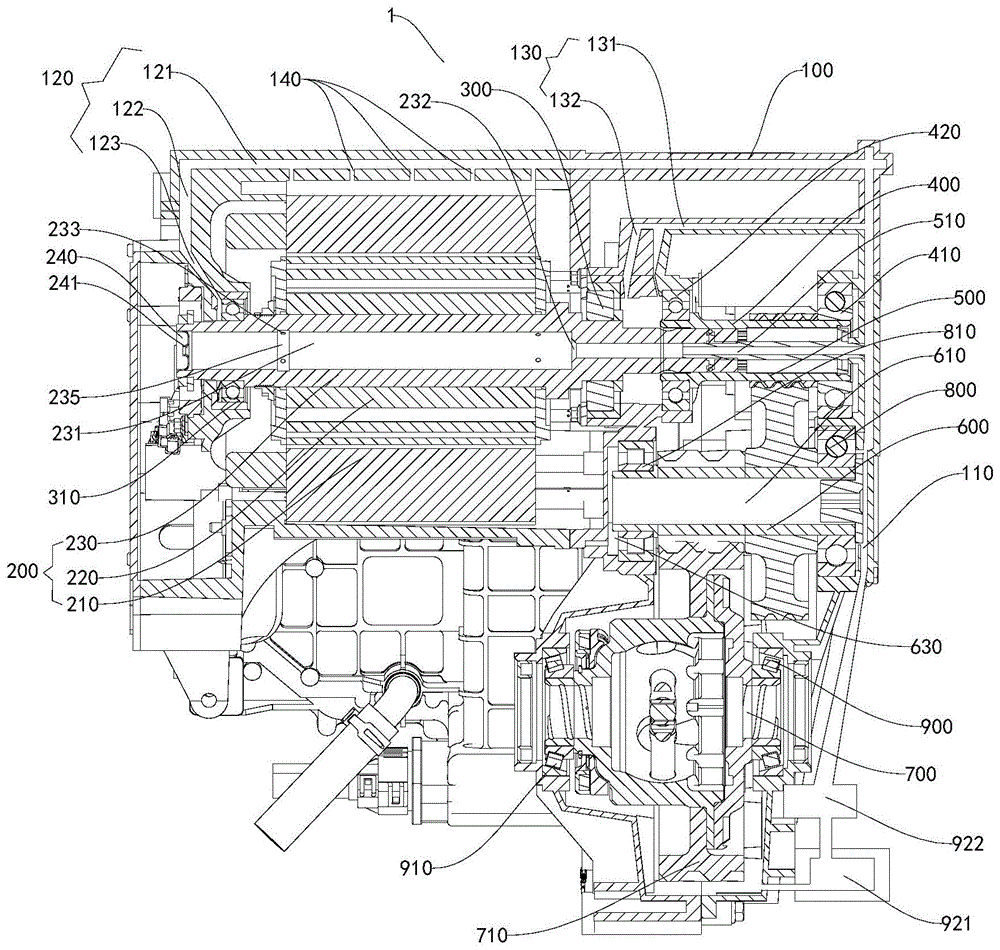
The invention discloses an electric assembly and a vehicle thereof. The electric assembly includes: a casing, the casing is provided with a cooling oil passage; a motor is arranged in the casing, and the motor It includes a stator, a rotor and a rotating shaft. The rotor is rotatably matched to the stator. The rotating shaft is connected to the rotor and driven by the rotor to rotate. A motor oil passage is constructed inside the rotating shaft. One end of the rotating shaft The end wall of the rotating shaft is provided with an oil inlet hole connecting the cooling oil passage and the motor oil passage, the peripheral wall of the rotating shaft is provided with a first oil outlet hole facing the stator, and the end wall at the other end of the rotating shaft is provided There are pressure balance holes. The electric assembly according to the embodiment of the present invention can balance the air pressure inside and outside the motor oil passage of the rotating shaft, so that the distribution of lubricating oil in the cooling oil passage is more balanced, and has the advantages of good cooling effect and high reliability.
Description
技术领域technical field
本发明涉及车辆技术领域,尤其是涉及一种电动总成和具有其的车辆。The invention relates to the technical field of vehicles, in particular to an electric assembly and a vehicle with the same.
背景技术Background technique
相关技术中的电动总成包括壳体和电机,电机包括定子、转子和转轴,且壳体设有冷却油道,转轴设有电机油道,电机油道与冷却油道连通,部分冷却介质可以由冷却油道进入电机油道对转子和定子进行冷却,以保证电机的正常工作。但是,转轴在高速旋转时会产生较大了离心力,进而使电机油道内处于负压状态,导致进入电机油道的冷却介质的流量过大,而减小了冷却油道向电动总成其他零件分配的冷却介质的流量,使电动总成内的冷却介质的流量分配不均衡,冷却效果较差,且可靠性低。The electric assembly in the related art includes a housing and a motor. The motor includes a stator, a rotor and a rotating shaft. The housing is provided with a cooling oil passage, and the rotating shaft is provided with a motor oil passage. The motor oil passage communicates with the cooling oil passage. Part of the cooling medium can The cooling oil passage enters the motor oil passage to cool the rotor and stator to ensure the normal operation of the motor. However, when the rotating shaft rotates at high speed, it will generate a large centrifugal force, which will cause the motor oil passage to be in a negative pressure state, resulting in an excessive flow of cooling medium entering the motor oil passage, reducing the flow of cooling oil passage to other parts of the electric assembly. The flow of the distributed cooling medium makes the flow distribution of the cooling medium in the electric assembly unbalanced, the cooling effect is poor, and the reliability is low.
发明内容Contents of the invention
本发明旨在至少解决现有技术中存在的技术问题之一。为此,本发明的一个目的在于提出一种电动总成,该电动总成能够平衡转轴的电机油道内外的气压,使冷却油道内的润滑油分配更加均衡,具有冷却效果好和可靠性高等优点。The present invention aims to solve at least one of the technical problems existing in the prior art. Therefore, an object of the present invention is to propose an electric assembly, which can balance the air pressure inside and outside the motor oil passage of the rotating shaft, so that the distribution of lubricating oil in the cooling oil passage is more balanced, and has good cooling effect and high reliability. advantage.
本发明还提出了一种具有上述电动总成的车辆。The invention also proposes a vehicle with the electric power assembly described above.
为了实现上述目的,本发明的第一方面实施例提出了一种电动总成,包括:壳体,所述壳体设有冷却油道;电机,所述电机设于所述壳体内,所述电机包括定子、转子和转轴,所述转子可旋转地配合于所述定子,所述转轴连接于所述转子且由所述转子带动旋转,所述转轴内构造有电机油道,所述转轴的一端的端壁设有连通所述冷却油道和所述电机油道的进油孔,所述转轴的周壁设有朝向所述定子的第一出油孔,所述转轴的另一端的端壁设有气压平衡孔。In order to achieve the above object, the embodiment of the first aspect of the present invention proposes an electric assembly, including: a casing, the casing is provided with a cooling oil passage; a motor, the motor is arranged in the casing, the The motor includes a stator, a rotor and a rotating shaft. The rotor is rotatably fitted to the stator. The rotating shaft is connected to the rotor and driven to rotate by the rotor. A motor oil passage is constructed inside the rotating shaft. The end wall at one end is provided with an oil inlet hole communicating with the cooling oil passage and the motor oil passage, the peripheral wall of the rotating shaft is provided with a first oil outlet hole facing the stator, and the end wall at the other end of the rotating shaft Equipped with air pressure balance hole.
根据本发明实施例的电动总成能够平衡转轴的电机油道内外的气压,使冷却油道内的润滑油分配更加均衡,具有冷却效果好和可靠性高等优点。The electric assembly according to the embodiment of the present invention can balance the air pressure inside and outside the motor oil passage of the rotating shaft, so that the distribution of lubricating oil in the cooling oil passage is more balanced, and has the advantages of good cooling effect and high reliability.
根据本发明的一些具体实施例,所述转轴的所述另一端伸出所述定子。According to some specific embodiments of the present invention, the other end of the rotating shaft extends out of the stator.
根据本发明的一些具体实施例,所述第一出油孔为多个且在所述转轴上排列成至少两圈,每圈第一出油孔包括沿所述转轴的周向排列的多个所述第一出油孔,所述至少两圈第一出油孔在所述转轴的轴向上分别位于所述转子的两侧且不超出所述定子。According to some specific embodiments of the present invention, there are multiple first oil outlet holes arranged in at least two circles on the rotating shaft, and each circle of first oil outlet holes includes a plurality of oil outlet holes arranged in the circumferential direction of the rotating shaft The first oil outlet holes, the at least two circles of first oil outlet holes are respectively located on both sides of the rotor in the axial direction of the rotating shaft and do not exceed the stator.
根据本发明的一些具体实施例,所述转轴的内周面设有沿其周向延伸的储油槽,距离所述进油孔最远的一圈第一出油孔贯通所述储油槽。According to some specific embodiments of the present invention, the inner peripheral surface of the rotating shaft is provided with an oil storage groove extending along its circumference, and a circle of first oil outlet holes farthest from the oil inlet holes passes through the oil storage groove.
根据本发明的一些具体实施例,所述气压平衡孔贯通所述转轴的所述另一端的端壁,所述电机油道内设有邻近所述气压平衡孔的挡油片,所述挡油片设有过孔。According to some specific embodiments of the present invention, the air pressure balance hole runs through the end wall of the other end of the rotating shaft, and an oil baffle sheet adjacent to the air pressure balance hole is provided in the motor oil passage, and the oil baffle plate The sheet has vias.
根据本发明的一些具体实施例,所述气压平衡孔的中心轴线、所述转轴的中心轴线和所述电机油道的中心轴线三者重合。According to some specific embodiments of the present invention, the central axis of the air pressure balance hole, the central axis of the rotating shaft and the central axis of the motor oil passage are coincident.
根据本发明的一些具体实施例,所述电动总成还包括:第一电机轴承和第二电机轴承,所述第一电机轴承和所述第二电机轴承安装于所述壳体内,所述转轴的两端分别支撑于所述第一电机轴承和所述第二电机轴承,所述冷却油道分别与所述第一电机轴承和所述第二电机轴承连通。According to some specific embodiments of the present invention, the electric assembly further includes: a first motor bearing and a second motor bearing, the first motor bearing and the second motor bearing are installed in the housing, and the rotating shaft The two ends of the motor are respectively supported on the first motor bearing and the second motor bearing, and the cooling oil channels are respectively communicated with the first motor bearing and the second motor bearing.
根据本发明的一些具体实施例,所述第一电机轴承邻近所述气压平衡孔设置,所述冷却油道包括与所述第一电机轴承连通的第一支路,所述第一支路包括:第一轴向段,所述第一轴向段沿所述壳体的轴向延伸;径向段,所述径向段沿所述壳体的径向延伸且与所述第一轴向段连通;第一倾斜段,所述第一倾斜段分别与所述径向段和所述第一电机轴承连通,所述第一倾斜段相对于所述第一轴向段和所述径向段倾斜设置。According to some specific embodiments of the present invention, the first motor bearing is disposed adjacent to the air pressure balance hole, the cooling oil passage includes a first branch communicating with the first motor bearing, and the first branch includes : a first axial section, the first axial section extends along the axial direction of the housing; a radial section, the radial section extends along the radial direction of the housing and is connected to the first axial section The section communicates; the first inclined section communicates with the radial section and the first motor bearing respectively, and the first inclined section is relatively to the first axial section and the radial Segment tilt settings.
根据本发明的一些具体实施例,所述第二电机轴承邻近所述进油孔设置,所述冷却油道包括与所述第二电机轴承连通的第二支路,所述第二支路包括:第二轴向段,所述第二轴向段沿所述壳体的轴向延伸;第二倾斜段,所述第二倾斜段分别与所述第二轴向段和所述第二电机轴承连通,所述第二倾斜段相对于所述第二轴向段倾斜设置。According to some specific embodiments of the present invention, the second motor bearing is arranged adjacent to the oil inlet hole, the cooling oil passage includes a second branch communicating with the second motor bearing, and the second branch includes : the second axial section, the second axial section extends along the axial direction of the housing; the second inclined section, the second inclined section is connected with the second axial section and the second motor respectively The bearings are connected, and the second inclined section is arranged obliquely relative to the second axial section.
根据本发明的一些具体实施例,所述定子套设于所述转子,所述第一出油孔朝向所述定子的内周面,所述冷却油道设有朝向所述定子的外周面的第二出油孔。According to some specific embodiments of the present invention, the stator is sleeved on the rotor, the first oil outlet hole faces the inner peripheral surface of the stator, and the cooling oil passage is provided with a hole facing the outer peripheral surface of the stator. Second oil outlet.
根据本发明的一些具体实施例,所述电动总成还包括:减速器,所述减速器安装于所述壳体且与所述转轴传动连接,所述减速器设有过渡油道,所述进油孔通过所述过渡油道与所述冷却油道连通。According to some specific embodiments of the present invention, the electric power assembly further includes: a speed reducer, the speed reducer is installed in the housing and connected to the rotating shaft in transmission, the speed reducer is provided with a transition oil passage, the The oil inlet hole communicates with the cooling oil passage through the transition oil passage.
根据本发明的一些具体实施例,所述减速器包括:输入轴,所述输入轴可转动地安装于所述壳体且与所述转轴传动连接,所述过渡油道设于所述输入轴;过渡轴,所述过渡轴可转动地安装于所述壳体且与所述输入轴传动连接;输出轴,所述输出轴可转动地安装于所述壳体且与所述过渡轴传动连接。According to some specific embodiments of the present invention, the speed reducer includes: an input shaft, the input shaft is rotatably mounted on the housing and connected to the rotating shaft in transmission, the transition oil passage is provided on the input shaft a transition shaft, the transition shaft is rotatably mounted on the housing and is in transmission connection with the input shaft; an output shaft, the output shaft is rotatably mounted in the housing and is in transmission connection with the transition shaft .
根据本发明的一些具体实施例,所述减速器还包括:第一输入轴承和第二输入轴承,所述第一输入轴承和所述第二输入轴承安装于所述壳体,所述输入轴的两端分别支撑于所述第一输入轴承和所述第二输入轴承,所述冷却油道分别与所述第一输入轴承和所述第二输入轴承连通。According to some specific embodiments of the present invention, the reducer further includes: a first input bearing and a second input bearing, the first input bearing and the second input bearing are mounted on the housing, and the input shaft The two ends of each are respectively supported by the first input bearing and the second input bearing, and the cooling oil passages communicate with the first input bearing and the second input bearing respectively.
根据本发明的一些具体实施例,所述减速器还包括:第一过渡轴承和第二过渡轴承,所述第一过渡轴承和所述第二过渡轴承安装于所述壳体,所述过渡轴的两端分别支撑于所述第一过渡轴承和所述第二过渡轴承,所述过渡轴内构造有过渡轴油道,所述冷却油道分别与所述过渡轴油道和所述第一过渡轴承连通,所述过渡轴设有第三出油孔,所述过渡轴与所述壳体之间形成连通所述第三出油孔和所述第二过渡轴承的过油间隙。According to some specific embodiments of the present invention, the reducer further includes: a first transition bearing and a second transition bearing, the first transition bearing and the second transition bearing are mounted on the housing, and the transition shaft The two ends of the transition shaft are respectively supported by the first transition bearing and the second transition bearing, and a transition shaft oil passage is constructed in the transition shaft, and the cooling oil passage is connected with the transition shaft oil passage and the first transition shaft respectively. The transition bearing communicates, the transition shaft is provided with a third oil outlet hole, and an oil passage gap connecting the third oil outlet hole and the second transition bearing is formed between the transition shaft and the housing.
根据本发明的一些具体实施例,所述减速器还包括:第一输出轴承和第二输出轴承,所述第一输出轴承和所述第二输出轴承安装于所述壳体,所述输出轴的两端分别支撑于所述第一输出轴承和所述第二输出轴承;其中,所述输出轴固定有输出齿轮,所述输出齿轮通过随所述输出轴旋转而将冷却油而搅起至所述第一输出轴承和所述第二输出轴承。According to some specific embodiments of the present invention, the reducer further includes: a first output bearing and a second output bearing, the first output bearing and the second output bearing are installed in the housing, and the output shaft The two ends of the output shaft are respectively supported on the first output bearing and the second output bearing; wherein, the output shaft is fixed with an output gear, and the output gear stirs the cooling oil by rotating with the output shaft to The first output bearing and the second output bearing.
根据本发明的第二方面实施例提出了一种车辆,包括根据本发明的第一方面实施例所述的电动总成。According to the embodiment of the second aspect of the present invention, a vehicle is provided, including the electric power assembly according to the embodiment of the first aspect of the present invention.
根据本发明的第二方面实施例提出的车辆,通过利用根据本发明的第一方面实施例所述的电动车身,能够平衡转轴的电机油道内外的气压,使冷却油道内的润滑油分配更加均衡,具有冷却效果好和可靠性高等优点。According to the vehicle proposed in the embodiment of the second aspect of the present invention, by using the electric vehicle body described in the embodiment of the first aspect of the present invention, the air pressure inside and outside the motor oil passage of the rotating shaft can be balanced, so that the distribution of lubricating oil in the cooling oil passage is more efficient. Balanced, with the advantages of good cooling effect and high reliability.
本发明的附加方面和优点将在下面的描述中部分给出,部分将从下面的描述中变得明显,或通过本发明的实践了解到。Additional aspects and advantages of the invention will be set forth in the description which follows, and in part will be obvious from the description, or may be learned by practice of the invention.
附图说明Description of drawings
本发明的上述和/或附加的方面和优点从结合下面附图对实施例的描述中将变得明显和容易理解,其中:The above and/or additional aspects and advantages of the present invention will become apparent and comprehensible from the description of the embodiments in conjunction with the following drawings, wherein:
图1是根据本发明实施例的电动总成的结构示意图。Fig. 1 is a schematic structural diagram of an electric power assembly according to an embodiment of the present invention.
图2是根据本发明实施例的电动总成的剖视图。Fig. 2 is a cross-sectional view of an electric power assembly according to an embodiment of the present invention.
图3是根据本发明实施例的冷却水道路径示意图。Fig. 3 is a schematic diagram of a cooling channel path according to an embodiment of the present invention.
图4是根据本发明另一实施例的电动总成的剖视图。Fig. 4 is a cross-sectional view of an electric power assembly according to another embodiment of the present invention.
附图标记:Reference signs:
电动总成1、Electric assembly 1,
壳体100、冷却油道110、第一支路120、第一轴向段121、径向段122、第一倾斜段123、第二支路130、第二轴向段131、第二倾斜段132、第二出油孔140、
电机200、定子210、转子220、转轴230、电机油道231、进油孔232、第一出油孔233、气压平衡孔234、储油槽235、挡油片240、过孔241、
第一电机轴承300、第二电机轴承310、The first motor bearing 300, the second motor bearing 310,
减速器400、第一输入轴承410、第二输入轴承420、Reducer 400, first input bearing 410, second input bearing 420,
输入轴500、过渡油道510、
过渡轴600、过渡轴油道610、第三出油孔620、过油间隙630、
输出轴700、输出齿轮710、
第一过渡轴承800、第二过渡轴承810、The first transition bearing 800, the second transition bearing 810,
第一输出轴承900、第二输出轴承910、油箱920、油泵921、过滤器922、油冷器923。The first output bearing 900 , the second output bearing 910 , the
具体实施方式Detailed ways
下面详细描述本发明的实施例,所述实施例的示例在附图中示出,其中自始至终相同或类似的标号表示相同或类似的元件或具有相同或类似功能的元件。下面通过参考附图描述的实施例是示例性的,仅用于解释本发明,而不能理解为对本发明的限制。Embodiments of the present invention are described in detail below, examples of which are shown in the drawings, wherein the same or similar reference numerals designate the same or similar elements or elements having the same or similar functions throughout. The embodiments described below by referring to the figures are exemplary only for explaining the present invention and should not be construed as limiting the present invention.
在本发明的描述中,需要理解的是,术语“中心”、“纵向”、“横向”、“长度”、“宽度”、“厚度”、“上”、“下”、“前”、“后”、“左”、“右”、“竖直”、“水平”、“顶”、“底”、“内”、“外”、“轴向”、“径向”、“周向”等指示的方位或位置关系为基于附图所示的方位或位置关系,仅是为了便于描述本发明和简化描述,而不是指示或暗示所指的装置或元件必须具有特定的方位、以特定的方位构造和操作,因此不能理解为对本发明的限制。In describing the present invention, it should be understood that the terms "center", "longitudinal", "transverse", "length", "width", "thickness", "upper", "lower", "front", " Rear", "Left", "Right", "Vertical", "Horizontal", "Top", "Bottom", "Inner", "Outer", "Axial", "Radial", "Circumferential" The orientation or positional relationship indicated by etc. is based on the orientation or positional relationship shown in the drawings, and is only for the convenience of describing the present invention and simplifying the description, rather than indicating or implying that the referred device or element must have a specific orientation, use a specific Azimuth configuration and operation, therefore, should not be construed as limiting the invention.
在本发明的描述中,“第一特征”、“第二特征”可以包括一个或者更多个该特征。In the description of the present invention, "first feature" and "second feature" may include one or more of these features.
在本发明的描述中,“多个”的含义是两个或两个以上,“若干”的含义是一个或多个。In the description of the present invention, "plurality" means two or more, and "several" means one or more.
下面参考附图描述根据本发明实施例的电动总成1。An electric power assembly 1 according to an embodiment of the present invention will be described below with reference to the drawings.
如图1-图4所示,本发明实施例的电动总成1包括壳体100和电机200。As shown in FIGS. 1-4 , the electric power assembly 1 of the embodiment of the present invention includes a
壳体100设有冷却油道110,电机200设于壳体100内,电机200包括定子210、转子220和转轴230,转子220可旋转地配合于定子210,转轴230连接于转子220且由转子220带动旋转,转轴230内构造有电机油道231,转轴230的一端的端壁设有连通冷却油道110和电机油道231的进油孔232,转轴230的周壁设有朝向定子210的第一出油孔233,转轴230的另一端的端壁设有气压平衡孔234。The
其中,冷却油道110和电机油道231中可以通入冷却介质,例如润滑油,润滑油可以在冷却油道110和电机油道231中流动以对电机200各部件进行冷却散热,保证电机200的正常工作。Wherein, the cooling medium, such as lubricating oil, can be passed into the cooling
另外,电动总成1还可以设有油泵921、过滤器922和油冷器923,油箱920、油泵921、过滤器922和油冷器923可以设于壳体100外,油泵921可以将润滑油抽起,并为润滑油提供在冷却油道110内流动的动力,润滑油进入油泵921之前可以先进行粗滤,避免大体积的杂质进入油泵921,润滑油被油泵921抽出后再经过过滤器922进行精滤,以彻底去除润滑油内的杂质,过滤后的润滑油通过油冷器923进行冷却降温后再通入冷却油道110,油冷器923可以设有散热翅片,以保证润滑油的温度较低,能够更好地对电机200进行散热。In addition, the electric assembly 1 can also be provided with an
根据本发明实施例的电动总成1,通过将电机200设于壳体100内,壳体100能够保护电机200,电机200包括定子210、转子220和转轴230,转子220可旋转地配合于定子210,转轴230连接于转子220且由转子220带动旋转,其中,转轴230与转子220同步转动,举例而言,定子210可以套设于转子220或者转子220可以套设于定子210。According to the electric assembly 1 of the embodiment of the present invention, by setting the
另外,壳体100设有冷却油道110,转轴230内构造有电机油道231,转轴230的一端的端壁设有连通冷却油道110和电机油道231的进油孔232,转轴230的周壁设有朝向定子210的第一出油孔233,即转轴230为空心结构,进油孔232可以设于转轴230的朝向冷却油道110的一端,以便于冷却油道110内的润滑油进入电机油道231,第一出油孔233贯穿转轴230的周壁,使电机油道231内的润滑油可以流向定子210,润滑油经过冷却油道110进入电机油道231后,润滑油可以从第一出油孔233对定子210散热,其中定子210可以套设于转子220,润滑油可以被由转轴230旋转而产生的离心力甩出至定子210,润滑油流向定子210的速度更快,提高了润滑油对定子210的散热效率,保证电机200工作的可靠性。In addition, the
此外,转轴230的另一端的端壁设有气压平衡孔234,气压平衡孔234设于转轴230的远离冷却油道110的一端,且气压平衡孔234沿转轴230的轴向贯穿转轴230的上述另一端。如此,电机油道231外的气体可以通过气压平衡孔234进入电机油道231,以使电机油道231内部的气压和外部的气压趋于相同,提高电机油道231内的压强,进而避免冷却油道110内的润滑油被吸入电机油道231内,冷却油道110内的润滑油可以更多地分配到电动总成1内其余的转动部件,即电机油道231内的润滑油的流量与分配到电动总成1内其余的转动部件的润滑油的流量保持均衡,从而提高电动总成1整体的转动效率和散热效果。In addition, the end wall of the other end of the
其中,本发明实施例中气压平衡孔234沿转轴230的轴向贯穿转轴230,且气压平衡孔234的中心轴线与转轴230的中心轴线可以重合,由于转轴230转动时转轴230会产生沿其周向的离心力,通过将气压平衡孔234的轴向和转轴230的转动轴线平行设置,能够极大地减小气压平衡孔234处的离心力,从而外部气体可以更流畅地从气压平衡孔234进入到电机油道231,以提升电机油道231内的压强,避免电机油道231内的压强处于负压状态。Wherein, in the embodiment of the present invention, the air
由此,根据本发明实施例的电动总成1能够平衡转轴230的电机油道231内外的气压,使冷却油道110内的润滑油分配更加均衡,具有冷却效果好和可靠性高等优点。Therefore, the electric assembly 1 according to the embodiment of the present invention can balance the air pressure inside and outside the
根据本发明的一些具体实施例,如图2和图4所示,转轴230的另一端伸出定子210,即转轴230的设有气压平衡孔234的一端伸出定子210,这样可以提高气压平衡孔234与外部空间连通效率,进而保持电机油道231内部的气压与外部的气压保持平衡,进一步避免电机油道231内产生负压,润滑油可以在电动总成1内均衡分配。而且,转轴230的另一端伸出定子210,可以便于转轴230的另一端和壳体100的固定。According to some specific embodiments of the present invention, as shown in Figure 2 and Figure 4, the other end of
根据本发明的一些具体实施例,如图2-图4所示,第一出油孔233为多个且在转轴230上排列成至少两圈,每圈第一出油孔233包括沿转轴230的周向排列的多个第一出油孔233。According to some specific embodiments of the present invention, as shown in FIGS. A plurality of first oil outlet holes 233 arranged in the circumferential direction.
如此,润滑油可以从每圈中的多个第一出油孔233流出电机油道231,从而保证润滑油可以在转轴230的周向上更为均匀地流向定子210,使润滑油与转子220和定子210充分接触,冷却效果更好。In this way, lubricating oil can flow out of the
并且,至少两圈第一出油孔233在转轴230的轴向上分别位于转子220的两侧且不超出定子210,这样多圈第一出油孔233在转轴230的轴向更为分散,润滑油在定子210的轴上对定子210散热更为均匀,以提高润滑油对定子210的冷却效果。Moreover, at least two circles of first oil outlet holes 233 are respectively located on both sides of the
进一步地,如图2和图4所示,转轴230的内周面设有沿其周向延伸的储油槽235,距离进油孔232最远的一圈第一出油孔233贯通储油槽235。Further, as shown in FIG. 2 and FIG. 4 , the inner peripheral surface of the
具体地,储油槽235的直径大于转轴230的内周面的直径,即储油槽235从转轴230的内周面沿转轴230的径向向外凹陷,如此,润滑油进入电机油道231后,在朝向气压平衡孔234流动的过程中会进入储油槽235,通过储油槽235可以储存部分润滑油,以避免电机油道231内的润滑油直接流向气压平衡孔234,从而能够减少润滑油流向气压平衡孔234的流量,避免润滑油从气压平衡孔234流出。Specifically, the diameter of the
根据本发明的一些具体实施例,如图2和图4所示,气压平衡孔234贯通转轴230的另一端的端壁,电机油道231内设有邻近气压平衡孔234的挡油片240,挡油片240设有过孔241。According to some specific embodiments of the present invention, as shown in FIG. 2 and FIG. 4 , the air
举例而言,挡油片240可以为压铸件,挡油片240能够进一步阻挡润滑油沿气压平衡孔234流出电机油道231,使润滑油主要由第一出油孔233流向定转子210,提高对定子210冷却效率,且由于过孔241与气压平衡孔234连通,因此空气可以由过孔241进入电机油道231,从而保证电机油道231内外的气压平衡,避免冷却油道110内的润滑油过度流向电机油道231。并且,挡油片240在电机油道231的内部结构(例如储油槽235)加工完成后在安装于转轴230。For example, the
根据本发明的一些具体实施例,如图2-图4所示,气压平衡孔234的中心轴线、转轴230的中心轴线和电机油道231的中心轴线三者重合。According to some specific embodiments of the present invention, as shown in FIGS. 2-4 , the central axis of the air
气压平衡孔234的中心轴线与转轴230的中心轴线重合可以尽可能地减小气压平衡孔234在转轴230转动时而产生的离心力,进而避免润滑油从气压平衡孔234甩出。The coincidence of the central axis of the air
转轴230的中心轴线和电机油道231的中心轴线重合可以保证电机油道231的周壁到转轴230的中心轴线的距离相同,使电机油道231的周壁的各个部分的离心力相同,润滑油可以被均匀甩出,进而使润滑油可以较均匀地与转子220以及定子210接触,转子220和定子210各部分热量均能够有效地得到降低。The coincidence of the central axis of the
根据本发明的一些具体实施例,如图2和图3所示,电动总成1还包括第一电机轴承300和第二电机轴承310。According to some specific embodiments of the present invention, as shown in FIGS. 2 and 3 , the electric assembly 1 further includes a first motor bearing 300 and a second motor bearing 310 .
第一电机轴承300和第二电机轴承310安装于壳体100内,转轴230的两端分别支撑于第一电机轴承300和第二电机轴承310,冷却油道110分别与第一电机轴承300和第二电机轴承310连通。The first motor bearing 300 and the second motor bearing 310 are installed in the
举例而言,转轴230的两端可以设置台阶,第一电机轴承300和第二电机轴承310在转轴230的轴向上止抵于台阶,以固定转轴230和壳体100的相对位置,避免转轴230在其轴向或径向上相对于壳体100发生位移,且使转轴230可以相对于壳体100进行更为流畅地转动,润滑油可以经冷却油道110流向第一电机轴承300和第二电机轴承310,以对第一电机轴承300和第二电机轴承310进行冷却散热,同时还可以对第一电机轴承300和第二电机轴承310进行润滑,有利于延长第一电机轴承300和第二电机轴承310的使用寿命,转动更加顺畅。For example, steps can be provided at both ends of the
进一步地,如图2所示,第一电机轴承300邻近气压平衡孔234设置,冷却油道110包括与第一电机轴承300连通的第一支路120。第一支路120包括第一轴向段121、径向段122和第一倾斜段123。Further, as shown in FIG. 2 , the first motor bearing 300 is disposed adjacent to the air
第一轴向段121沿壳体100的轴向延伸,径向段122沿壳体100的径向延伸且与第一轴向段121连通,第一倾斜段123分别与径向段122和第一电机轴承300连通,第一倾斜段123相对于第一轴向段121和径向段122倾斜设置。其中,第一支路120可以将润滑油导向第一电机轴承300,以通过润滑油对第一电机轴承300进行冷却和润滑。The first
这样,能够避免第一支路120与其他零部件(例如定子210)发生干涉,进而保证润滑油在第一支路120内流通顺畅,且第一支路120布置较合理,有利于减小电动总成1的整体体积,而且第一支路120路径较长,可以通过第一支路120将润滑油引向多个零部件,进而提高电机200总成的整体冷却效率。In this way, the interference between the
另外,第一倾斜段123可以减缓润滑油由第一径向段122流向第一电机轴承300的流动速度,使润滑油缓慢流向第一电机轴承300,润滑油能够对第一电机轴承300进行充分冷却和润滑,延长第一电机轴承300的使用寿命。In addition, the first
如图2所示,第二电机轴承310邻近进油孔232设置,冷却油道110包括与第二电机轴承310连通的第二支路130,第二支路130包括第二轴向段131和第二倾斜段132。As shown in Figure 2, the second motor bearing 310 is arranged adjacent to the
第二轴向段131沿壳体100的轴向延伸,第二倾斜段132分别与第二轴向段131和第二电机轴承310连通,第二倾斜段132相对于第二轴向段131倾斜设置。The second
第二支路130可以将润滑油导向第二电机轴承310,以通过润滑油对第二电机轴承310进行冷却和润滑。其中,第二倾斜段132可以引导润滑油流向第二电机轴承310,且第二倾斜段132可以减缓润滑油由第二轴向段131流向第二电机轴承310的流动速度,使润滑油缓慢流向第二电机轴承310,润滑油能够对第二电机轴承310进行充分冷却和润滑,延长第二电机轴承310的使用寿命。The
根据本发明的一些具体实施例,如图2和图3所示,定子210套设于转子220,第一出油孔233朝向定子210的内周面,冷却油道110设有朝向定子210的外周面的第二出油孔140。According to some specific embodiments of the present invention, as shown in FIG. 2 and FIG. 3 , the
具体地,第二出油孔140可以设于第一轴向段121的朝向定子210的一侧,且第二出油孔140不超出于定子210的两端,如此,一部分润滑油可以由第一出油孔233流向定子210的内周面,另一部分润滑油可以由第二出油孔140流向定子210的外周面,进而定子210的内周面和外周面都可以被润滑油冷却散热,进一步提高了定子210的散热效率,有利于使电机200处于高效地工作状态。Specifically, the second
根据本发明的一些具体实施例,如图2和图3所示,电动总成1还包括减速器400。According to some specific embodiments of the present invention, as shown in FIGS. 2 and 3 , the electric assembly 1 further includes a
减速器400安装于壳体100且与转轴230传动连接,减速器400连接于转轴230的设有进油孔232的一端,减速器400设有过渡油道510,进油孔232通过过渡油道510与冷却油道110连通。The
润滑油可以由冷却油道110进入过渡油道510,再通过过渡油道510和进油孔232流入电机油道231内,如此实现了冷却油道110与电机油道231的连通,润滑油可以顺利流入电机油道231,且润滑油流经过渡油道510时还可以对减速器400进行冷却散热,进而降低减速器400的温度。由于减速器400和电机200共同安装于壳体100,能够减少电动总成1的零件数量,减小电动总成1的体积。The lubricating oil can enter the
进一步地,如图2所示,减速器400还包括输入轴500、过渡轴600和输出轴700。Further, as shown in FIG. 2 , the
输入轴500可转动地安装于壳体100且与转轴230传动连接,过渡油道510设于输入轴500,过渡轴600可转动地安装于壳体100且与输入轴500传动连接,输出轴700可转动地安装于壳体100且与过渡轴600传动连接。The
具体地,输入轴500的转动轴线与转轴230的转动轴线可以重合,过渡油道510的中心轴线、进油孔232的中心轴线和电机油道231的中心轴线可以重合,因此既能够实现转轴230与输入轴500之间的动力传输,又能够保证在转轴230与输入轴500转动时过渡油道510、进油孔232和电机油道231持续连通。Specifically, the rotation axis of the
另外,输入轴500、过渡轴600和输出轴700之间异轴布置,且过渡轴600位于输入轴500和输出轴700之间,输入轴500的转动轴线、过渡轴600的转动轴线和输出轴700的转动轴线可以平行,便于输入轴500、过渡轴600和输出轴700之间进行动力传输,且能够减小壳体100的轴向尺寸。In addition, the
需要说明的是,输入轴500、过渡轴600和输出轴700均设有齿轮,过渡轴600的齿轮为两个,过渡轴600的一个齿轮与输入轴500的齿轮啮合,过渡轴600的另一个齿轮与输出轴700的齿轮啮合,这样转轴230输出的动力通过减速器400传递到车轮,车轮的转速低于转轴230的转速,车轮的扭矩高于转轴230的扭矩,车辆运动更为平稳。It should be noted that the
更进一步地,如图2和图3所示,减速器400还包括第一输入轴承410和第二输入轴承420。Furthermore, as shown in FIGS. 2 and 3 , the
第一输入轴承410和第二输入轴承420安装于壳体100,输入轴500的两端分别支撑于第一输入轴承410和第二输入轴承420,冷却油道110分别与第一输入轴承410和第二输入轴承420连通。The first input bearing 410 and the second input bearing 420 are installed in the
通过设置第一输入轴承410和第二输入轴承420,输入轴500相对于壳体100的转动更为流畅,有利于提高输入轴500和转轴230之间的动力传输效率。另外,润滑油可以经冷却油道110流向第一输入轴承410和第二输入轴承420,以对第一输入轴承410和第二输入轴承420进行冷却散热,同时还可以对第一输入轴承410和第二输入轴承420进行润滑,有利于延长第一输入轴承410和第二输入轴承420的使用寿命,转动更加顺畅。By arranging the first input bearing 410 and the second input bearing 420 , the rotation of the
可选地,如图2和图3所示,减速器400还包括第一过渡轴承800和第二过渡轴承810。Optionally, as shown in FIGS. 2 and 3 , the
第一过渡轴承800和第二过渡轴承810安装于壳体100,过渡轴600的两端分别支撑于第一过渡轴承800和第二过渡轴承810,过渡轴600内构造有过渡轴油道610,冷却油道110分别与过渡轴油道610和第一过渡轴承800连通,过渡轴600设有第三出油孔620,过渡轴600与壳体100之间形成连通第二出油孔140和第二过渡轴承810的过油间隙630。The first transition bearing 800 and the second transition bearing 810 are installed in the
第一过渡轴承800和第二过渡轴承810可以固定过渡轴600和壳体100的相对位置,避免过渡轴600在其轴向或径向上相对于壳体100位移,且使过渡轴600可以相对于壳体100进行更为流畅地转动,有利于提高过渡轴600和输入轴500之间的动力传输效率。The first transition bearing 800 and the second transition bearing 810 can fix the relative position of the
其中,一部分润滑油可以直接通过冷却油道110流向第一过渡轴承800,以对第一过渡轴承800进行润滑和散热,另一部分润滑油可以经冷却油道110流入过渡轴油道610,该部分润滑油再通过第三出油孔620和过油间隙630流向第二过渡轴承810,以对第二过渡轴承810进行散热和润滑,由此,第一过渡轴承800和第二过渡轴承810均得到散热,有利于延长第一过渡轴承800和第二过渡轴承810的使用寿命,转动更为流畅。Wherein, a part of the lubricating oil can directly flow to the first transition bearing 800 through the cooling
根据本发明的一些具体实施例,如图2和图3所示,减速器400还包括第一输出轴承900和第二输出轴承910。According to some specific embodiments of the present invention, as shown in FIGS. 2 and 3 , the
第一输出轴承900和第二输出轴承910安装于壳体100,输出轴700的两端分别支撑于第一输出轴承900和第二输出轴承910。第一输出轴承900和第二输出轴承910可以固定输出轴700和壳体100的相对位置,避免输出轴700在其轴向或径向上相对于壳体100发生位移,且使输出轴700可以相对于壳体100进行更为流畅地转动,有利于提高过渡轴600和输出轴700之间的动力传输效率。The
其中,输出轴700固定有输出齿轮710,输出齿轮710通过随输出轴700旋转而将润滑油而搅起至第一输出轴承900和第二输出轴承910。Wherein, the
具体地,润滑油储存于电动总成1的油箱920内,输出齿轮710可以伸入油箱920内的润滑油的油面以下,这样,当输出轴700带动输出齿轮710转动时即可将润滑油搅起以对第一输出轴承900和第二输出轴承910进行冷却和散热,有利于延长第一输出轴承900和第二输出轴承910的使用寿命,转动更为流畅。Specifically, lubricating oil is stored in the
下面参考附图描述根据本发明实施例的车辆,车辆包括电动总成1。A vehicle including an electric powertrain 1 will be described below according to an embodiment of the present invention with reference to the drawings.
根据本发明实施例的车辆,通过利用根据本发明实施例上述的电动总成1,能够平衡转轴230的电机油道231内外的气压,使冷却油道110内的润滑油分配更加均衡,具有冷却效果好和可靠性高等优点。According to the vehicle according to the embodiment of the present invention, by using the above-mentioned electric power assembly 1 according to the embodiment of the present invention, the air pressure inside and outside the
根据本发明实施例的电动总成1和具有其的车辆的其他构成以及操作对于本域普通技术人员而言都是已知的,这里不再详细描述。Other configurations and operations of the electric power assembly 1 according to the embodiment of the present invention and the vehicle having the same are known to those skilled in the art, and will not be described in detail here.
在本说明书的描述中,参考术语“具体实施例”、“具体示例”等的描述意指结合该实施例或示例描述的具体特征、结构、材料或者特点包含于本发明的至少一个实施例或示例中。在本说明书中,对上述术语的示意性表述不一定指的是相同的实施例或示例。In the description of this specification, descriptions with reference to the terms "specific embodiment", "specific example" and the like mean that specific features, structures, materials or characteristics described in conjunction with the embodiment or example are included in at least one embodiment or embodiment of the present invention. example. In this specification, schematic representations of the above terms do not necessarily refer to the same embodiment or example.
尽管已经示出和描述了本发明的实施例,本领域的普通技术人员可以理解:在不脱离本发明的原理和宗旨的情况下可以对这些实施例进行多种变化、修改、替换和变型,本发明的范围由权利要求及其等同物限定。Although the embodiments of the present invention have been shown and described, those skilled in the art can understand that various changes, modifications, substitutions and modifications can be made to these embodiments without departing from the principle and spirit of the present invention. The scope of the invention is defined by the claims and their equivalents.
Claims (16)
Priority Applications (1)
| Application Number | Priority Date | Filing Date | Title |
|---|---|---|---|
| CN202110990329.7A CN115733288A (en) | 2021-08-26 | 2021-08-26 | Electric assembly and vehicle with same |
Applications Claiming Priority (1)
| Application Number | Priority Date | Filing Date | Title |
|---|---|---|---|
| CN202110990329.7A CN115733288A (en) | 2021-08-26 | 2021-08-26 | Electric assembly and vehicle with same |
Publications (1)
| Publication Number | Publication Date |
|---|---|
| CN115733288A true CN115733288A (en) | 2023-03-03 |
Family
ID=85290076
Family Applications (1)
| Application Number | Title | Priority Date | Filing Date |
|---|---|---|---|
| CN202110990329.7A Pending CN115733288A (en) | 2021-08-26 | 2021-08-26 | Electric assembly and vehicle with same |
Country Status (1)
| Country | Link |
|---|---|
| CN (1) | CN115733288A (en) |
Cited By (3)
| Publication number | Priority date | Publication date | Assignee | Title |
|---|---|---|---|---|
| CN120402616A (en) * | 2025-07-04 | 2025-08-01 | 比亚迪股份有限公司 | Drive axle assembly and vehicle |
| CN120444400A (en) * | 2024-02-07 | 2025-08-08 | 华为数字能源技术有限公司 | Powertrain and vehicle for oil injection through reducer shaft |
| WO2026131267A1 (en) * | 2024-12-19 | 2026-06-25 | Valeo Electrification Sas | Rotor for electric machine with improved coolant distribution and electric machine, drive unit as well as vehicle and operating methods thereto |
Citations (7)
| Publication number | Priority date | Publication date | Assignee | Title |
|---|---|---|---|---|
| JP2011205770A (en) * | 2010-03-25 | 2011-10-13 | Fuji Heavy Ind Ltd | Cooling structure of motor |
| CN105966230A (en) * | 2015-12-31 | 2016-09-28 | 比亚迪股份有限公司 | Electric drive axle assembly and vehicle with electric drive axle assembly |
| CN109038951A (en) * | 2018-07-24 | 2018-12-18 | 上海大郡动力控制技术有限公司 | The cooling structure of new-energy automobile electrical drive power assembly |
| US20190207481A1 (en) * | 2016-08-09 | 2019-07-04 | Nidec Corporation | Drive device |
| CN110149018A (en) * | 2018-02-12 | 2019-08-20 | 比亚迪股份有限公司 | Electric assembly and vehicle having the same |
| CN110311504A (en) * | 2019-07-23 | 2019-10-08 | 珠海格力电器股份有限公司 | Driving motor and automobile |
| CN111884427A (en) * | 2020-06-19 | 2020-11-03 | 华为技术有限公司 | Motor, power assembly and electric automobile |
-
2021
- 2021-08-26 CN CN202110990329.7A patent/CN115733288A/en active Pending
Patent Citations (7)
| Publication number | Priority date | Publication date | Assignee | Title |
|---|---|---|---|---|
| JP2011205770A (en) * | 2010-03-25 | 2011-10-13 | Fuji Heavy Ind Ltd | Cooling structure of motor |
| CN105966230A (en) * | 2015-12-31 | 2016-09-28 | 比亚迪股份有限公司 | Electric drive axle assembly and vehicle with electric drive axle assembly |
| US20190207481A1 (en) * | 2016-08-09 | 2019-07-04 | Nidec Corporation | Drive device |
| CN110149018A (en) * | 2018-02-12 | 2019-08-20 | 比亚迪股份有限公司 | Electric assembly and vehicle having the same |
| CN109038951A (en) * | 2018-07-24 | 2018-12-18 | 上海大郡动力控制技术有限公司 | The cooling structure of new-energy automobile electrical drive power assembly |
| CN110311504A (en) * | 2019-07-23 | 2019-10-08 | 珠海格力电器股份有限公司 | Driving motor and automobile |
| CN111884427A (en) * | 2020-06-19 | 2020-11-03 | 华为技术有限公司 | Motor, power assembly and electric automobile |
Cited By (4)
| Publication number | Priority date | Publication date | Assignee | Title |
|---|---|---|---|---|
| CN120444400A (en) * | 2024-02-07 | 2025-08-08 | 华为数字能源技术有限公司 | Powertrain and vehicle for oil injection through reducer shaft |
| WO2025167160A1 (en) * | 2024-02-07 | 2025-08-14 | 华为数字能源技术有限公司 | Power assembly achieving oil injection by means of rotating shaft of gearbox, and vehicle |
| WO2026131267A1 (en) * | 2024-12-19 | 2026-06-25 | Valeo Electrification Sas | Rotor for electric machine with improved coolant distribution and electric machine, drive unit as well as vehicle and operating methods thereto |
| CN120402616A (en) * | 2025-07-04 | 2025-08-01 | 比亚迪股份有限公司 | Drive axle assembly and vehicle |
Similar Documents
| Publication | Publication Date | Title |
|---|---|---|
| US11434977B2 (en) | Vehicle drive device | |
| CN112271876B (en) | Oil-cooled motor | |
| JP6664302B2 (en) | Vehicle drive system | |
| CN113905917A (en) | Power assembly and electric vehicle | |
| CN109538743A (en) | A kind of water-cooled machine fore bearing oil lubrication mechanism and motor driven assembly | |
| JP2021052521A (en) | Motor unit | |
| WO2023010947A1 (en) | Cooling and lubrication apparatus of electrical drive assembly, and electrical drive assembly | |
| CN111697743A (en) | Dual cooling assembly | |
| JP2015072054A (en) | Drive unit | |
| WO2020032026A1 (en) | Motor unit | |
| JP2017063542A (en) | In-wheel motor drive drive | |
| WO2019208083A1 (en) | Motor unit | |
| CN116394742A (en) | Cooling and lubricating device for electric drive assembly and electric drive assembly | |
| EP4456379A1 (en) | Electric drive assembly and an electric device | |
| US12492745B2 (en) | Speed reducer, powertrain, and vehicle | |
| CN115416464A (en) | Drive system and vehicle | |
| CN111503033A (en) | Forced heat exchange type speed-increasing air pump | |
| CN214888767U (en) | Cooling system of motor assembly, motor assembly and hybrid electric vehicle | |
| JP2017123761A (en) | In-wheel motor driving device | |
| CN213585388U (en) | Oil-cooled motor shell | |
| CN112253741A (en) | Be used for trinity power assembly | |
| CN215072021U (en) | Electric assembly and vehicle having the same | |
| JP2018043682A (en) | In-wheel motor drive device | |
| CN110323895B (en) | Pure electric vehicle drive system and its drive motor oil cooling system | |
| CN111911793B (en) | Motors, vehicles |
Legal Events
| Date | Code | Title | Description |
|---|---|---|---|
| PB01 | Publication | ||
| PB01 | Publication | ||
| SE01 | Entry into force of request for substantive examination | ||
| SE01 | Entry into force of request for substantive examination |