CN115719723A - A quality inspection device for photovoltaic panel production - Google Patents
A quality inspection device for photovoltaic panel production Download PDFInfo
- Publication number
- CN115719723A CN115719723A CN202310010303.0A CN202310010303A CN115719723A CN 115719723 A CN115719723 A CN 115719723A CN 202310010303 A CN202310010303 A CN 202310010303A CN 115719723 A CN115719723 A CN 115719723A
- Authority
- CN
- China
- Prior art keywords
- photovoltaic panel
- frame
- slider
- rod
- fixed
- Prior art date
- Legal status (The legal status is an assumption and is not a legal conclusion. Google has not performed a legal analysis and makes no representation as to the accuracy of the status listed.)
- Granted
Links
Images




Classifications
-
- Y—GENERAL TAGGING OF NEW TECHNOLOGICAL DEVELOPMENTS; GENERAL TAGGING OF CROSS-SECTIONAL TECHNOLOGIES SPANNING OVER SEVERAL SECTIONS OF THE IPC; TECHNICAL SUBJECTS COVERED BY FORMER USPC CROSS-REFERENCE ART COLLECTIONS [XRACs] AND DIGESTS
- Y02—TECHNOLOGIES OR APPLICATIONS FOR MITIGATION OR ADAPTATION AGAINST CLIMATE CHANGE
- Y02E—REDUCTION OF GREENHOUSE GAS [GHG] EMISSIONS, RELATED TO ENERGY GENERATION, TRANSMISSION OR DISTRIBUTION
- Y02E10/00—Energy generation through renewable energy sources
- Y02E10/50—Photovoltaic [PV] energy
Landscapes
- Photovoltaic Devices (AREA)
Abstract
本发明涉及质量检测机架技术领域,具体的说是一种光伏板生产用质量检测装置,包括外壳、驱动结构、框架、支撑结构、夹持结构、定位结构和限位结构;通过限位结构便于调节定位结构的位置,使定位结构配合框架对光伏板前后两侧定位,使光伏板固定更加稳定,便于调节支撑结构的位置,对光伏板的左右两侧进行定位和支撑,使光伏板的固定效果更好,同时便于对大小不同的光伏板进行定位,通过夹持结构配合支撑结构便于从上下方向夹持固定光伏板,采用托起的方式固定光伏板,减小了对光伏板的压力,避免光伏板损坏,同时便于对不同厚度的光伏板进行夹持,驱动结构驱动框架翻转,便于对光伏板的不同位置进行检测。

The invention relates to the technical field of quality inspection racks, in particular to a quality inspection device for photovoltaic panel production, which includes a casing, a drive structure, a frame, a support structure, a clamping structure, a positioning structure and a limit structure; It is convenient to adjust the position of the positioning structure, so that the positioning structure cooperates with the frame to position the front and rear sides of the photovoltaic panel, so that the fixing of the photovoltaic panel is more stable, and it is convenient to adjust the position of the support structure, and the left and right sides of the photovoltaic panel are positioned and supported, so that the photovoltaic panel The fixing effect is better, and at the same time, it is convenient to locate photovoltaic panels of different sizes. The clamping structure cooperates with the supporting structure to facilitate the clamping and fixing of photovoltaic panels from the upper and lower directions. The photovoltaic panel is fixed by lifting, which reduces the pressure on the photovoltaic panel. , to avoid damage to the photovoltaic panel, and at the same time, it is convenient to clamp photovoltaic panels of different thicknesses, and the driving structure drives the frame to turn over, which is convenient for detecting different positions of the photovoltaic panel.
Description
技术领域technical field
本发明涉及质量检测机架技术领域,具体的说是一种光伏板生产用质量检测装置。The invention relates to the technical field of quality inspection racks, in particular to a quality inspection device for photovoltaic panel production.
背景技术Background technique
光伏板生产制造过程中,需要对其成品进行质量检测工作,主要是对其有无隐裂、碎片、虚焊、断栅及不同转换效率单片电池异常现象进行检测,在进行检测工作时,成品光伏板在输送带上输送,通过机械手臂吸盘将其放置在检测工作平台上,之后再对质量合格的和不合格的成品光伏板进行分拣工作,在这过程中,只对光伏板的一面进行扫描检测,之后还要对其背面进行扫描检测,例如在公开号为:CN112145898B的发明专利公开了一种光伏板生产用质量检测机构。During the production and manufacturing process of photovoltaic panels, it is necessary to carry out quality inspection of the finished products, mainly to detect whether there are hidden cracks, fragments, virtual welding, broken grids and abnormal phenomena of monolithic cells with different conversion efficiencies. During the inspection work, The finished photovoltaic panels are conveyed on the conveyor belt, placed on the inspection work platform by the suction cup of the mechanical arm, and then the qualified and unqualified finished photovoltaic panels are sorted. In this process, only the photovoltaic panels One side is scanned for detection, and then the back side is scanned for detection. For example, the invention patent with the publication number: CN112145898B discloses a quality detection mechanism for photovoltaic panel production.
然而,公开号为CN112145898B的发明专利中公开的一种光伏板生产用质量检测机构中采用了复杂的结构从侧边固定光伏板,结构繁琐,不利于检修维护,同时从侧边夹持固定光伏板,依赖摩擦力对光伏板进行夹持,当夹持力度过大容易造成光伏板损坏,当夹持力度较小,会导致稳定性差,且不便于对大小不同的光伏板进行夹持固定,通用性差。However, a quality inspection mechanism for photovoltaic panel production disclosed in the invention patent with the publication number CN112145898B adopts a complex structure to fix the photovoltaic panel from the side, which is cumbersome and unfavorable for maintenance. Plates rely on friction to clamp photovoltaic panels. When the clamping force is too large, it is easy to cause damage to the photovoltaic panel. When the clamping force is small, it will lead to poor stability, and it is not convenient to clamp and fix photovoltaic panels of different sizes. Poor versatility.
发明内容Contents of the invention
针对现有技术中的问题,本发明提供了一种光伏板生产用质量检测装置。Aiming at the problems in the prior art, the invention provides a quality detection device for photovoltaic panel production.
本发明解决其技术问题所采用的技术方案是:一种光伏板生产用质量检测装置,包括外壳,所述外壳上设有驱动结构,驱动结构驱动框架进行翻转;所述框架上设有用于对光伏板进行定位的定位结构,所述框架上设有用于对定位结构进行固定的限位结构;所述框架上设有用于托起光伏板的支撑结构,所述支撑结构配合框架上的夹持结构夹持固定光伏板;The technical solution adopted by the present invention to solve the technical problem is: a quality detection device for photovoltaic panel production, including a casing, the casing is provided with a driving structure, and the driving structure drives the frame to turn over; The positioning structure for positioning the photovoltaic panel, the frame is provided with a limiting structure for fixing the positioning structure; the frame is provided with a support structure for holding up the photovoltaic panel, and the support structure cooperates with the clamping structure on the frame The structure clamps and fixes the photovoltaic panel;
所述支撑结构包括两个第一滑块,所述框架上滑动设有两个第一滑块,所述第一滑块上固定有支撑条,所述支撑条的截面呈L形,所述第一滑块上固定有导向座;The support structure includes two first sliders, two first sliders are slidably arranged on the frame, a support bar is fixed on the first slider, the cross section of the support bar is L-shaped, and the A guide seat is fixed on the first slider;
所述夹持结构包括驱动轴,所述导向座上转动设有驱动轴,所述驱动轴与第一滑块之间转动连接,所述驱动轴上固定有夹板,所述夹板上固定有橡胶套,所述驱动轴的端部固定有转盘,所述转盘的边缘处转动设有导向轮,所述框架上固定有液压缸,所述液压缸的伸缩端固定有驱动条,所述驱动条上设有导向槽,所述导向轮在导向槽中滚动。The clamping structure includes a drive shaft, the drive shaft is rotated on the guide seat, the drive shaft is connected to the first slider in rotation, a splint is fixed on the drive shaft, and rubber is fixed on the splint The end of the drive shaft is fixed with a turntable, the edge of the turntable is rotated with a guide wheel, the frame is fixed with a hydraulic cylinder, the telescopic end of the hydraulic cylinder is fixed with a drive bar, and the drive bar A guide groove is arranged on the top, and the guide wheel rolls in the guide groove.
具体的,所述框架上设有导轨,所述支撑条背离第一滑块的一端与导轨之间滑动连接。Specifically, a guide rail is provided on the frame, and the end of the support bar away from the first slider is slidably connected to the guide rail.
具体的,所述第一滑块的底端螺纹连接有第一旋钮,所述第一旋钮与框架之间抵触,通过第一旋钮抵触框架使第一滑块无法移动。Specifically, a first knob is threadedly connected to the bottom end of the first slider, and the first knob interferes with the frame, and the first slider cannot move when the first knob interferes with the frame.
具体的,所述框架上固定有导向杆,所述驱动条在导向杆上滑动。Specifically, a guide rod is fixed on the frame, and the driving bar slides on the guide rod.
具体的,所述驱动结构包括轴承座和电机,所述外壳的左右两侧分别固定有轴承座和电机,所述轴承座上转动设有转轴,所述转轴、电机的输出轴和框架的两侧均固定有法兰盘,相邻的两个法兰盘之间通过螺栓固定。Specifically, the drive structure includes a bearing seat and a motor, and the left and right sides of the housing are respectively fixed with the bearing seat and the motor. Flanges are fixed on both sides, and two adjacent flanges are fixed by bolts.
具体的,所述定位结构包括两个第二滑块,所述框架上滑动设有两个第二滑块,所述第二滑块的底端转动设有连接杆,所述连接杆与定位板之间转动连接,两个所述连接杆之间转动连接且呈“X”形。Specifically, the positioning structure includes two second sliders, two second sliders are slid on the frame, and the bottom end of the second slider is rotated with a connecting rod, and the connecting rod and the positioning The plates are rotatably connected, and the two connecting rods are rotatably connected in an "X" shape.
具体的,其中一个第二滑块上固定有滑杆,所述滑杆与另外有一个第二滑块之间滑动连接,所述滑杆上设有多个第一限位孔。Specifically, a slide bar is fixed on one of the second slide blocks, and the slide bar is slidably connected to another second slide block, and a plurality of first limiting holes are provided on the slide bar.
具体的,所述限位结构包括限位杆,右侧的所述第二滑块上滑动设有限位杆,所述限位杆与第一限位孔卡合,所述限位杆上固定有把手,所述限位杆背离第二滑块的一侧与框架上的第二限位孔卡合,所述框架上的第二限位孔等距设有多个。Specifically, the limiting structure includes a limiting rod, a limiting rod is slid on the second slider on the right side, the limiting rod is engaged with the first limiting hole, and the limiting rod is fixed There is a handle, and the side of the limit rod facing away from the second slider engages with the second limit hole on the frame, and there are multiple second limit holes on the frame equidistantly.
具体的,所述限位杆背离第二滑块的一端呈T形,所述限位杆贯穿于弹簧,所述弹簧的两端分别抵触于第二滑块和限位杆。Specifically, the end of the limiting rod facing away from the second slider is T-shaped, the limiting rod passes through the spring, and the two ends of the spring are in contact with the second sliding block and the limiting rod respectively.
具体的,所述限位结构包括限位杆,右侧的所述第二滑块上滑动设有限位杆,所述限位杆与滑杆之间抵触,所述限位杆上固定有把手,所述限位杆背离第二滑块的一侧与框架上的滑槽之间滑动连接,所述限位杆背离第二滑块的一端呈T形,所述限位杆上螺纹连接有第二旋钮,所述第二旋钮贯穿于滑槽,所述第二旋钮与框架之间抵触。Specifically, the limiting structure includes a limiting rod, a limiting rod is slid on the second slider on the right side, the limiting rod interferes with the sliding rod, and a handle is fixed on the limiting rod , the side of the limit rod away from the second slider is slidably connected to the chute on the frame, the end of the limit rod away from the second slider is T-shaped, and the limit rod is threadedly connected with The second knob, the second knob passes through the sliding slot, and the second knob interferes with the frame.
本发明的有益效果是:The beneficial effects of the present invention are:
(1)本发明所述的一种光伏板生产用质量检测装置,所述框架上设有用于对光伏板进行定位的定位结构,所述框架上设有用于对定位结构进行固定的限位结构,通过限位结构便于调节定位结构的位置,使定位结构配合框架对光伏板前后两侧定位,使光伏板固定更加稳定。(1) A quality inspection device for photovoltaic panel production according to the present invention, the frame is provided with a positioning structure for positioning the photovoltaic panel, and the frame is provided with a limiting structure for fixing the positioning structure , the position of the positioning structure can be easily adjusted through the limiting structure, so that the positioning structure cooperates with the frame to position the front and rear sides of the photovoltaic panel, so that the fixing of the photovoltaic panel is more stable.
(2)本发明所述的一种光伏板生产用质量检测装置,框架上设有用于托起光伏板的支撑结构,便于调节支撑结构的位置,对光伏板的左右两侧进行定位和支撑,使光伏板的固定效果更好,便于对大小不同的光伏板进行定位。(2) A quality inspection device for photovoltaic panel production according to the present invention, the frame is provided with a support structure for holding up the photovoltaic panel, which is convenient for adjusting the position of the support structure, positioning and supporting the left and right sides of the photovoltaic panel, The fixing effect of the photovoltaic panel is better, and it is convenient to locate photovoltaic panels of different sizes.
(3)本发明所述的一种光伏板生产用质量检测装置,支撑结构配合框架上的夹持结构夹持固定光伏板,通过夹持结构配合支撑结构便于从上下方向夹持固定光伏板,采用托起的方式固定光伏板,减小了对光伏板的压力,避免光伏板损坏,同时便于对不同厚度的光伏板进行夹持,驱动结构驱动框架翻转,便于对光伏板的不同位置进行检测。(3) A quality inspection device for photovoltaic panel production according to the present invention, the supporting structure cooperates with the clamping structure on the frame to clamp and fix the photovoltaic panel, and the clamping structure cooperates with the supporting structure to facilitate clamping and fixing the photovoltaic panel from the up and down direction, The photovoltaic panel is fixed by lifting, which reduces the pressure on the photovoltaic panel and avoids damage to the photovoltaic panel. At the same time, it is convenient to clamp photovoltaic panels of different thicknesses. The driving structure drives the frame to turn over, which is convenient for detecting different positions of the photovoltaic panel. .
附图说明Description of drawings
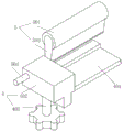
图1为本发明提供的一种光伏板生产用质量检测装置的第一实施例和第二实施例的整体结构示意图;Fig. 1 is the overall structure schematic diagram of the first embodiment and the second embodiment of a quality detection device for photovoltaic panel production provided by the present invention;
图2为图1所示的A部结构放大示意图;Figure 2 is an enlarged schematic view of the structure of part A shown in Figure 1;
图3为图1所示的B部结构放大示意图;FIG. 3 is an enlarged schematic diagram of the structure of part B shown in FIG. 1;
图4为图1所示的C部结构放大示意图;FIG. 4 is an enlarged schematic diagram of the structure of part C shown in FIG. 1;
图5为图2所示的D部结构放大示意图;FIG. 5 is an enlarged schematic diagram of the structure of part D shown in FIG. 2;
图6为图2所示的E部结构放大示意图;Figure 6 is an enlarged schematic view of the structure of part E shown in Figure 2;
图7为本发明的第一实施例和第二实施例的支撑结构与夹持结构的连接结构示意图;Fig. 7 is a schematic diagram of the connection structure between the support structure and the clamping structure of the first embodiment and the second embodiment of the present invention;
图8为本发明的定位结构的结构示意图;Fig. 8 is a structural schematic diagram of the positioning structure of the present invention;
图9为本发明提供的第一实施例的定位结构与限位结构的连接结构示意图Fig. 9 is a schematic diagram of the connection structure of the positioning structure and the limiting structure of the first embodiment provided by the present invention
图10为本发明提供的第二实施例的定位结构与限位结构的连接结构示意图。Fig. 10 is a schematic diagram of the connection structure of the positioning structure and the limiting structure according to the second embodiment of the present invention.
图中:1、外壳;2、驱动结构;201、轴承座;202、电机;203、法兰盘;204、转轴;3、框架;4、支撑结构;401、支撑条;402、第一滑块;403、导轨;404、导向座;405、第一旋钮;5、夹持结构;501、橡胶套;502、驱动条;503、夹板;504、驱动轴;505、导向轮;506、转盘;507、导向槽;508、导向杆;509、液压缸;6、定位结构;601、定位板;602、滑杆;603、第一限位孔;604、第二滑块;605、连接杆;7、限位结构;701、限位杆;702、把手;703、弹簧;704、第二限位孔;705、第二旋钮;706、滑槽。In the figure: 1. shell; 2. drive structure; 201. bearing seat; 202. motor; 203. flange; 204. shaft; 3. frame; 4. support structure; 401. support bar; 402. first slide Block; 403, guide rail; 404, guide seat; 405, first knob; 5, clamping structure; 501, rubber sleeve; 502, drive bar; 503, splint; 504, drive shaft; 505, guide wheel; 506, turntable ; 507, guide groove; 508, guide rod; 509, hydraulic cylinder; 6, positioning structure; 601, positioning plate; 7, limit structure; 701, limit rod; 702, handle; 703, spring; 704, second limit hole; 705, second knob; 706, chute.
具体实施方式Detailed ways
为了使本发明实现的技术手段、创作特征、达成目的与功效易于明白了解,下面结合具体实施方式,进一步阐述本发明。In order to make the technical means, creative features, goals and effects achieved by the present invention easy to understand, the present invention will be further described below in conjunction with specific embodiments.
实施例一Embodiment one
如图1-图9所示,本发明实施例一提出的一种光伏板生产用质量检测装置包括外壳1,所述外壳1上设有驱动结构2,驱动结构2驱动框架3进行翻转;所述框架3上设有用于对光伏板进行定位的定位结构6,所述框架3上设有用于对定位结构6进行固定的限位结构7;所述框架3上设有用于托起光伏板的支撑结构4,所述支撑结构4配合框架3上的夹持结构5夹持固定光伏板。As shown in Figures 1 to 9, a photovoltaic panel production quality detection device proposed in
所述定位结构6包括两个第二滑块604,所述框架3上滑动设有两个第二滑块604,所述第二滑块604的底端转动设有连接杆605,所述连接杆605与定位板601之间转动连接,两个所述连接杆605之间转动连接且呈“X”形,其中一个第二滑块604上固定有滑杆602,所述滑杆602与另外有一个第二滑块604之间滑动连接,所述滑杆602上设有多个第一限位孔603;The
所述限位结构7包括限位杆701,右侧的所述第二滑块604上滑动设有限位杆701,所述限位杆701与第一限位孔603卡合,所述限位杆701上固定有把手702,所述限位杆701背离第二滑块604的一侧与框架3上的第二限位孔704卡合,所述框架3上的第二限位孔704等距设有多个,所述限位杆701背离第二滑块604的一端呈T形,所述限位杆701贯穿于弹簧703,所述弹簧703的两端分别抵触于第二滑块604和限位杆701;The
手握把手702,向上拉动把手702,把手702带动限位杆701向上滑动,使限位杆701带动弹簧703压缩,使限位杆701的左右两端分别不与第一限位孔603和第二限位孔704卡合,然后推动把手702,使限位杆701带动第二滑块604与框架3滑动,拉动滑杆602与第二滑块604滑动,使两个第二滑块604之间的距离改变,第二滑块604上的两个连接杆605转动,连接杆605与定位板601转动,同时推动定位板601移动,然后松开把手702,弹簧703伸长驱动限位杆701复位,使限位杆701的两端分别与第一限位孔603和第二限位孔704卡合,使第二滑块604、滑杆602无法移动,从而使定位板601无法移动,通过定位板601配合框架3对光伏板前后方向定位。Hold the
具体的,所述支撑结构4包括两个第一滑块402,所述框架3上滑动设有两个第一滑块402,所述第一滑块402上固定有支撑条401,所述支撑条401的截面呈L形,所述第一滑块402上固定有导向座404;所述第一滑块402的底端螺纹连接有第一旋钮405,所述第一旋钮405与框架3之间抵触,通过第一旋钮405抵触框架3使第一滑块402无法移动;Specifically, the
转动第一旋钮405,使第一旋钮405与框架3不抵触,然后滑动第一滑块402,当两个第一滑块402之间距离改变后,转动第一旋钮405,使第一旋钮405抵触框架3,对第一滑块402进行限位,支撑条401呈L形,便于托起光伏板,对光伏板的支撑效果更好,便于对大小不同的光伏板进行定位。Turn the
具体的,所述框架3上设有导轨403,所述支撑条401背离第一滑块402的一端与导轨403之间滑动连接;在第一滑块402滑动过程中,支撑条401与导轨403滑动,使对支撑条401的支撑效果更好。Specifically, the
所述夹持结构5包括驱动轴504,所述导向座404上转动设有驱动轴504,所述驱动轴504与第一滑块402之间转动连接,所述驱动轴504上固定有夹板503,所述夹板503上固定有橡胶套501,所述驱动轴504的端部固定有转盘506,所述转盘506的边缘处转动设有导向轮505,所述框架3上固定有液压缸509,所述液压缸509的伸缩端固定有驱动条502,所述驱动条502上设有导向槽507,所述导向轮505在导向槽507中滚动,所述框架3上固定有导向杆508,所述驱动条502在导向杆508上滑动;The clamping
在第一滑块402滑动过程中,导向轮505在导向槽507中左右滑动,不会影响整个传动,当机械手将光伏板放置在支撑条401上后,液压缸509收缩,液压缸509带动驱动条502与导向杆508滑动,驱动条502带动导向轮505在导向槽507中滚动,导向槽507在竖直方向上距离驱动轴504的轴心距离改变,从而使导向轮505带动转盘506转动,两个所述转盘506的转动方向相反,转盘506带动驱动轴504与第一滑块402转动,驱动轴504带动夹板503转动,使夹板503上的橡胶套501配合支撑条401夹持光伏板,从而上下夹持光伏板,将光伏板托起,减小了光伏板夹持过程中的摩擦力,使夹持固定效果更好,且结构简单,操作灵活。During the sliding process of the
具体的,所述驱动结构2包括轴承座201和电机202,所述外壳1的左右两侧分别固定有轴承座201和电机202,所述轴承座201上转动设有转轴204,所述转轴204、电机202的输出轴和框架3的两侧均固定有法兰盘203,相邻的两个法兰盘203之间通过螺栓固定;Specifically, the drive structure 2 includes a
可以在外壳1的底端安装两个脚踩开关,通过脚踩开关控制电机202和液压缸509工作,电机202转动,电机202的输出轴通过法兰盘203带动框架3转动,使转轴204与轴承座201转动,从而便于对框架3上的光伏板不同面进行检测。Two foot switches can be installed at the bottom of the
实施例二Embodiment two
如图1-8和图10所示,本实施例二提出的一种光伏板生产用质量检测装置与上述实施例一的区别特征在于,所述限位结构7包括限位杆701,右侧的所述第二滑块604上滑动设有限位杆701,所述限位杆701与滑杆602之间抵触,所述限位杆701上固定有把手702,所述限位杆701背离第二滑块604的一侧与框架3上的滑槽706之间滑动连接,所述限位杆701背离第二滑块604的一端呈T形,所述限位杆701上螺纹连接有第二旋钮705,所述第二旋钮705贯穿于滑槽706,所述第二旋钮705与框架3之间抵触;As shown in Figures 1-8 and Figure 10, the difference between the quality inspection device for photovoltaic panel production proposed in this embodiment 2 and the above-mentioned
转动第二旋钮705,第二旋钮705与限位杆701之间螺纹连接,使第二旋钮705的底端与限位杆701的距离增大,使第二旋钮705与框架3不抵触,手握把手702,向上拉动把手702,把手702带动限位杆701向上滑动,使限位杆701与滑杆602不抵触,然后推动把手702,使限位杆701带动第二滑块604与框架3滑动,限位杆701和第二旋钮705在滑槽706上滑动,拉动滑杆602与第二滑块604滑动,使两个第二滑块604之间的距离改变,第二滑块604上的两个连接杆605转动,连接杆605与定位板601转动,同时推动定位板601移动,然后松开把手702,反向转动第二旋钮705,第二旋钮705与框架3抵触,使限位杆701与滑杆602抵触,使第二滑块604、滑杆602无法移动,从而使定位板601无法移动,通过定位板601配合框架3对光伏板前后方向定位。Rotate the second knob 705, threaded connection between the second knob 705 and the limit rod 701, so that the distance between the bottom end of the second knob 705 and the limit rod 701 increases, so that the second knob 705 does not conflict with the frame 3, and the hand Hold the handle 702, pull the handle 702 upward, the handle 702 drives the limit rod 701 to slide upward, so that the limit rod 701 does not conflict with the slide rod 602, and then push the handle 702, so that the limit rod 701 drives the second slider 604 and the frame 3 Sliding, the limit rod 701 and the second knob 705 slide on the chute 706, pull the slide bar 602 to slide with the second slider 604, so that the distance between the two second sliders 604 changes, and the second slider 604 The two connecting rods 605 rotate, the connecting rod 605 and the positioning plate 601 rotate, and at the same time push the positioning plate 601 to move, then release the handle 702, turn the second knob 705 in the opposite direction, the second knob 705 conflicts with the frame 3, and the limit The rod 701 is in conflict with the sliding rod 602, so that the second sliding block 604 and the sliding rod 602 cannot move, so that the positioning plate 601 cannot move, and the positioning plate 601 cooperates with the frame 3 to position the photovoltaic panel in the front and rear direction.
本发明在使用时,首先根据光伏板的型号调节定位板601的位置,当采用实施例一中的结构调节定位板601的位置时,手握把手702,向上拉动把手702,把手702带动限位杆701向上滑动,使限位杆701带动弹簧703压缩,使限位杆701的左右两端分别不与第一限位孔603和第二限位孔704卡合,然后推动把手702,使限位杆701带动第二滑块604与框架3滑动,拉动滑杆602与第二滑块604滑动,使两个第二滑块604之间的距离改变,第二滑块604上的两个连接杆605转动,连接杆605与定位板601转动,同时推动定位板601移动,然后松开把手702,弹簧703伸长驱动限位杆701复位,使限位杆701的两端分别与第一限位孔603和第二限位孔704卡合,使第二滑块604、滑杆602无法移动,从而使定位板601无法移动,通过定位板601配合框架3对光伏板前后方向定位;When the present invention is in use, first adjust the position of the
当采用实施例二中的结构调节定位板601的位置时,转动第二旋钮705,第二旋钮705与限位杆701之间螺纹连接,使第二旋钮705的底端与限位杆701的距离增大,使第二旋钮705与框架3不抵触,手握把手702,向上拉动把手702,把手702带动限位杆701向上滑动,使限位杆701与滑杆602不抵触,然后推动把手702,使限位杆701带动第二滑块604与框架3滑动,限位杆701和第二旋钮705在滑槽706上滑动,拉动滑杆602与第二滑块604滑动,使两个第二滑块604之间的距离改变,第二滑块604上的两个连接杆605转动,连接杆605与定位板601转动,同时推动定位板601移动,然后松开把手702,反向转动第二旋钮705,第二旋钮705与框架3抵触,使限位杆701与滑杆602抵触,使第二滑块604、滑杆602无法移动,从而使定位板601无法移动,通过定位板601配合框架3对光伏板前后方向定位,实施例一中操作较为便捷,但稳定性不如实施例二,且实施例二中调节范围更加精确;When adopting the structure in the second embodiment to adjust the position of the positioning plate 601, turn the second knob 705, and the screw connection between the second knob 705 and the limit rod 701 makes the bottom end of the second knob 705 and the limit rod 701 Increase the distance so that the second knob 705 does not interfere with the frame 3, hold the handle 702, pull the handle 702 upwards, the handle 702 drives the limit rod 701 to slide upward, so that the limit rod 701 does not conflict with the slide rod 602, and then push the handle 702, make the limit rod 701 drive the second slider 604 to slide with the frame 3, the limit rod 701 and the second knob 705 slide on the chute 706, pull the slide rod 602 and the second slide block 604 to slide, so that the two first The distance between the two sliders 604 changes, the two connecting rods 605 on the second slider 604 rotate, the connecting rods 605 and the positioning plate 601 rotate, and at the same time push the positioning plate 601 to move, then release the handle 702, reversely rotate the second The second knob 705, the second knob 705 is in conflict with the frame 3, so that the limit rod 701 is in conflict with the slide bar 602, so that the second slider 604 and the slide bar 602 cannot move, so that the positioning plate 601 cannot move, and the positioning plate 601 cooperates Frame 3 positions the front and rear directions of the photovoltaic panel. The operation in the first embodiment is more convenient, but the stability is not as good as that in the second embodiment, and the adjustment range in the second embodiment is more accurate;
然后转动第一旋钮405,使第一旋钮405与框架3不抵触,然后滑动第一滑块402,当两个第一滑块402之间距离改变后,转动第一旋钮405,使第一旋钮405抵触框架3,对第一滑块402进行限位,在第一滑块402滑动过程中,支撑条401与导轨403滑动,使对支撑条401的支撑效果更好,且支撑条401呈L形,便于托起光伏板,对光伏板的支撑效果更好,便于对大小不同的光伏板进行定位;Then turn the
在第一滑块402滑动过程中,导向轮505在导向槽507中左右滑动,不会影响整个传动,当机械手将光伏板放置在支撑条401上后,液压缸509收缩,液压缸509带动驱动条502与导向杆508滑动,驱动条502带动导向轮505在导向槽507中滚动,导向槽507在竖直方向上距离驱动轴504的轴心距离改变,从而使导向轮505带动转盘506转动,两个所述转盘506的转动方向相反,转盘506带动驱动轴504与第一滑块402转动,驱动轴504带动夹板503转动,使夹板503上的橡胶套501配合支撑条401夹持光伏板,从而上下夹持光伏板,将光伏板托起,减小了光伏板夹持过程中的摩擦力,使夹持固定效果更好,且结构简单,操作灵活;During the sliding process of the
可以在外壳1的底端安装两个脚踩开关,通过脚踩开关控制电机202和液压缸509工作,电机202转动,电机202的输出轴通过法兰盘203带动框架3转动,使转轴204与轴承座201转动,从而便于对框架3上的光伏板不同面进行检测。Two foot switches can be installed at the bottom of the
对于本领域技术人员而言,显然本发明不限于上述示范性实施例的细节,而且在不背离本发明的精神或基本特征的情况下,能够以其他的具体形式实现本发明。因此,无论从哪一点来看,均应将实施例看作是示范性的,而且是非限制性的,本发明的范围由所附权利要求而不是上述说明限定,因此旨在将落在权利要求的等同要件的含义和范围内的所有变化囊括在本发明内。不应将权利要求中的任何附图标记视为限制所涉及的权利要求。It will be apparent to those skilled in the art that the invention is not limited to the details of the above-described exemplary embodiments, but that the invention can be embodied in other specific forms without departing from the spirit or essential characteristics of the invention. Accordingly, the embodiments should be regarded in all points of view as exemplary and not restrictive, the scope of the invention being defined by the appended claims rather than the foregoing description, and it is therefore intended that the scope of the invention be defined by the appended claims rather than by the foregoing description. All changes within the meaning and range of equivalents of the elements are embraced in the present invention. Any reference sign in a claim should not be construed as limiting the claim concerned.
此外,应当理解,虽然本说明书按照实施方式加以描述,但并非每个实施方式仅包含一个独立的技术方案,说明书的这种叙述方式仅仅是为清楚起见,本领域技术人员应当将说明书作为一个整体,各实施例中的技术方案也可以经适当组合,形成本领域技术人员可以理解的其他实施方式。In addition, it should be understood that although this specification is described according to implementation modes, not each implementation mode only includes an independent technical solution, and this description in the specification is only for clarity, and those skilled in the art should take the specification as a whole , the technical solutions in the various embodiments can also be properly combined to form other implementations that can be understood by those skilled in the art.
Claims (10)
Priority Applications (1)
| Application Number | Priority Date | Filing Date | Title |
|---|---|---|---|
| CN202310010303.0A CN115719723B (en) | 2023-01-05 | 2023-01-05 | Quality detection device is used in photovoltaic board production |
Applications Claiming Priority (1)
| Application Number | Priority Date | Filing Date | Title |
|---|---|---|---|
| CN202310010303.0A CN115719723B (en) | 2023-01-05 | 2023-01-05 | Quality detection device is used in photovoltaic board production |
Publications (2)
| Publication Number | Publication Date |
|---|---|
| CN115719723A true CN115719723A (en) | 2023-02-28 |
| CN115719723B CN115719723B (en) | 2023-04-07 |
Family
ID=85257833
Family Applications (1)
| Application Number | Title | Priority Date | Filing Date |
|---|---|---|---|
| CN202310010303.0A Active CN115719723B (en) | 2023-01-05 | 2023-01-05 | Quality detection device is used in photovoltaic board production |
Country Status (1)
| Country | Link |
|---|---|
| CN (1) | CN115719723B (en) |
Citations (8)
| Publication number | Priority date | Publication date | Assignee | Title |
|---|---|---|---|---|
| CN207998273U (en) * | 2018-03-31 | 2018-10-23 | 锦州阳光锦懋光伏科技有限公司 | Photovoltaic grillage detection turnover device |
| CN210200693U (en) * | 2019-10-21 | 2020-03-27 | 保定中科新能源系统质量检测有限公司 | Supporting device for photovoltaic module EL test |
| CN214901758U (en) * | 2021-05-28 | 2021-11-26 | 成都航域卓越电子技术有限公司 | LLC circuit-based fixed structure for efficiency detection |
| CN215734152U (en) * | 2021-04-25 | 2022-02-01 | 上海美客铝制品有限公司 | An assembly adjustable photovoltaic panel mounting bracket |
| CN216313049U (en) * | 2021-11-24 | 2022-04-15 | 西藏大学 | A photovoltaic module auxiliary test device |
| CN114679124A (en) * | 2022-04-08 | 2022-06-28 | 青岛宝强太阳能科技有限公司 | A spliced photovoltaic solar panel installation device |
| CN216904771U (en) * | 2022-03-10 | 2022-07-05 | 河南双龙新能源有限公司 | Fixing piece of solar photovoltaic panel |
| CN217992458U (en) * | 2022-09-02 | 2022-12-09 | 中认南信(江苏)检测技术有限公司 | Photovoltaic module detects uses turning device |
-
2023
- 2023-01-05 CN CN202310010303.0A patent/CN115719723B/en active Active
Patent Citations (8)
| Publication number | Priority date | Publication date | Assignee | Title |
|---|---|---|---|---|
| CN207998273U (en) * | 2018-03-31 | 2018-10-23 | 锦州阳光锦懋光伏科技有限公司 | Photovoltaic grillage detection turnover device |
| CN210200693U (en) * | 2019-10-21 | 2020-03-27 | 保定中科新能源系统质量检测有限公司 | Supporting device for photovoltaic module EL test |
| CN215734152U (en) * | 2021-04-25 | 2022-02-01 | 上海美客铝制品有限公司 | An assembly adjustable photovoltaic panel mounting bracket |
| CN214901758U (en) * | 2021-05-28 | 2021-11-26 | 成都航域卓越电子技术有限公司 | LLC circuit-based fixed structure for efficiency detection |
| CN216313049U (en) * | 2021-11-24 | 2022-04-15 | 西藏大学 | A photovoltaic module auxiliary test device |
| CN216904771U (en) * | 2022-03-10 | 2022-07-05 | 河南双龙新能源有限公司 | Fixing piece of solar photovoltaic panel |
| CN114679124A (en) * | 2022-04-08 | 2022-06-28 | 青岛宝强太阳能科技有限公司 | A spliced photovoltaic solar panel installation device |
| CN217992458U (en) * | 2022-09-02 | 2022-12-09 | 中认南信(江苏)检测技术有限公司 | Photovoltaic module detects uses turning device |
Also Published As
| Publication number | Publication date |
|---|---|
| CN115719723B (en) | 2023-04-07 |
Similar Documents
| Publication | Publication Date | Title |
|---|---|---|
| CN118528217B (en) | Adjustable tool for automatic nondestructive testing | |
| CN115719723B (en) | Quality detection device is used in photovoltaic board production | |
| CN218726223U (en) | Static bending force detection device of flexible circuit board | |
| CN110817434A (en) | Watch lens turnover device | |
| CN208034510U (en) | A kind of special positioning installation apparatus of novel electrical engineering | |
| CN221223711U (en) | Detection device for surface flatness of silicon disc | |
| CN219788100U (en) | Supporting equipment for processing filter water cooling plate | |
| CN118425157A (en) | An optical inspection device for product appearance and size inspection | |
| CN215317913U (en) | A stainless steel plate polishing device | |
| CN117104885A (en) | Telescopic multi-point positioning type inspection rack mechanism for glass substrate | |
| CN114833219A (en) | Automatic safety straightening device for steel structure column beam | |
| CN115377249A (en) | Photovoltaic backplate demolish device | |
| CN218639467U (en) | Quick positioning clamp | |
| CN224223153U (en) | Photovoltaic module frame auxiliary assembly equipment | |
| CN209797767U (en) | A glass cutting device for solar photovoltaic glass production | |
| CN222696406U (en) | Frock clamp is used in fixed counterpoint of hardware | |
| CN221246564U (en) | A bending machine for convenient plate positioning | |
| CN222452676U (en) | Full-lamination film pasting device for touch film with color 3D stereoscopic display effect | |
| CN222086998U (en) | A steel structure level detection device | |
| CN221916027U (en) | Audio test jig transfer device | |
| CN217991117U (en) | Welded tube cutting processing device | |
| CN218254229U (en) | Positioning device for water milling processing of plates | |
| CN217675364U (en) | Clamping positioning and rotary conveying mechanism for curved surface back plate | |
| CN224190062U (en) | PCBA electrical property testboard | |
| CN224143327U (en) | A bending machine lower die mounting mechanism |
Legal Events
| Date | Code | Title | Description |
|---|---|---|---|
| PB01 | Publication | ||
| PB01 | Publication | ||
| SE01 | Entry into force of request for substantive examination | ||
| SE01 | Entry into force of request for substantive examination | ||
| GR01 | Patent grant | ||
| GR01 | Patent grant | ||
| PP01 | Preservation of patent right |
Effective date of registration: 20260422 Granted publication date: 20230407 |