CN115684640A - Wind power detection system and detection method of wind driven generator - Google Patents
Wind power detection system and detection method of wind driven generator Download PDFInfo
- Publication number
- CN115684640A CN115684640A CN202211422421.4A CN202211422421A CN115684640A CN 115684640 A CN115684640 A CN 115684640A CN 202211422421 A CN202211422421 A CN 202211422421A CN 115684640 A CN115684640 A CN 115684640A
- Authority
- CN
- China
- Prior art keywords
- wind
- shaft
- shaped
- worm
- wind power
- Prior art date
- Legal status (The legal status is an assumption and is not a legal conclusion. Google has not performed a legal analysis and makes no representation as to the accuracy of the status listed.)
- Pending
Links
Images



Classifications
-
- Y—GENERAL TAGGING OF NEW TECHNOLOGICAL DEVELOPMENTS; GENERAL TAGGING OF CROSS-SECTIONAL TECHNOLOGIES SPANNING OVER SEVERAL SECTIONS OF THE IPC; TECHNICAL SUBJECTS COVERED BY FORMER USPC CROSS-REFERENCE ART COLLECTIONS [XRACs] AND DIGESTS
- Y02—TECHNOLOGIES OR APPLICATIONS FOR MITIGATION OR ADAPTATION AGAINST CLIMATE CHANGE
- Y02E—REDUCTION OF GREENHOUSE GAS [GHG] EMISSIONS, RELATED TO ENERGY GENERATION, TRANSMISSION OR DISTRIBUTION
- Y02E10/00—Energy generation through renewable energy sources
- Y02E10/70—Wind energy
- Y02E10/72—Wind turbines with rotation axis in wind direction
Landscapes
- Wind Motors (AREA)
Abstract
The invention discloses a wind power detection system and a detection method of a wind driven generator, and belongs to the technical field of wind driven generators. Including main shaft and support frame, install the connecting axle in the support frame, connect through belt transmission between main shaft and the connecting axle, still include: the device comprises a U-shaped seat arranged on a support frame, wherein a cabin is arranged in the U-shaped seat through bolts, a chronic shaft, a gear box and a motor are arranged in the cabin, a triangular mounting frame is fixedly arranged at one end of the chronic shaft, which is far away from the cabin, and fan blades are rotatably arranged in the triangular mounting frame; a sliding sleeve is slidably arranged on the chronic shaft, and an adjusting piece is connected between the sliding sleeve and the fan blade; the rectangular groove box is fixedly installed on the supporting frame, the advancing direction of a third pull rod of the L-shaped clamping plate provided with the U-shaped clamping seat is opposite to that of the second pull rod in the rectangular groove box in a rotating mode, the third pull rod extends into the rectangular groove box, the end portion of the third pull rod is abutted to the pressing plate, the pressing plate drives the L-shaped clamping plate to rotate, the U-shaped clamping seat is clamped, and the requirements that the wind speed is larger and the clamping is tighter are met.
Description
Technical Field
The invention relates to the technical field of wind driven generators, in particular to a wind power detection system and a wind power detection method of a wind driven generator.
Background
Wind energy is a clean and pollution-free renewable energy source. The wind power generation device is utilized by people for a long time, mainly pumps water, grinds surfaces and the like through a windmill, people are interested in how to generate electricity by utilizing wind, the wind power generation is very environment-friendly, and the amount of wind energy is huge, so the wind power generation device is increasingly paid attention to all countries in the world.
The wind driven generator is very important power generating equipment in the modern society, the working principle is simple, the wind wheel rotates under the action of wind force, the kinetic energy of the wind is converted into the mechanical energy of a wind wheel shaft, and the generator rotates under the driving of the wind wheel shaft to generate power.
The existing wind power detection device is detachably mounted on any rod piece for improving the maneuverability, but due to the detachable structure, a swayable gap is always reserved between the wind power detection device and the rod piece, and particularly, the swaying of the wind power detection device is more obvious along with the increase of wind power, so that the rotating stability of fan blades is poor.
Disclosure of Invention
The invention aims to solve the problems that in the prior art, a swaying gap is reserved between a wind power detection device and a rod piece, and particularly, the swaying of the wind power detection device is more obvious along with the increase of wind power, so that the stability of the rotation of fan blades is poor.
In order to achieve the purpose, the invention adopts the following technical scheme:
the utility model provides a aerogenerator's wind-force detecting system, includes main shaft and support frame, the connecting axle is installed to the support frame internal rotation, connect through belt transmission between main shaft and the connecting axle, still include: the fan blade support is characterized by comprising a U-shaped seat arranged on a support frame, a cabin is arranged in the U-shaped seat through bolts, a chronic shaft, a gear box and a motor are arranged in the cabin, a triangular mounting frame is fixedly arranged at one end, far away from the cabin, of the chronic shaft, and fan blades are rotatably arranged in the triangular mounting frame; the sliding sleeve is slidably arranged on the chronic shaft, and an adjusting part is connected between the sliding sleeve and the fan blades; the rectangular groove box is fixedly installed on the supporting frame, and an L-shaped clamping plate for clamping the U-shaped seat is rotatably installed in the rectangular groove box.
In order to vary the pitch to maintain the stability of the motor, preferably, the adjustment member comprises: the triangular plate is fixedly arranged in the sliding sleeve, an L-shaped connecting rod is fixedly arranged on the triangular plate, a connecting pin is rotatably arranged in the L-shaped connecting rod, and one end of the connecting pin, far away from the L-shaped connecting rod, is fixedly connected with the fan blade; the connecting lugs are symmetrically arranged below the U-shaped seat, first pull rods are connected in the connecting lugs in a sliding mode, one ends of the first pull rods are respectively connected with two sides of the sliding sleeve in a rotating mode, and first connecting rods are arranged at the other ends of the first pull rods in a rotating mode; the second pull rod is rotatably installed below the first connecting rod, one end, far away from the first connecting rod, of the second pull rod is rotatably connected with the second connecting rod, and the second connecting rod is fixedly connected with the connecting shaft.
In order to improve the stability of the fan blades during rotation, a sliding hole and a third pull rod which is matched with the sliding hole and slides in the sliding hole are arranged on one side, close to the cabin, of the rectangular groove box, and a pressing plate which is abutted to the L-shaped clamping plate is fixedly arranged at one end, located in the rectangular groove box, of the third pull rod.
In order to measure the rotating speed, furthermore, a first conical tooth is coaxially arranged on the chronic shaft, a detection part is fixedly arranged below the support frame, an output shaft of the detection part penetrates through the support frame and is provided with a second conical tooth, and the second conical tooth is meshed with the first conical tooth.
In order to convert the wind power into the wind power, the detection element is further provided with an encoder.
In order to improve the heat radiation performance of the nacelle, it is preferable that the nacelle further includes: the adjusting plate is arranged above the rectangular groove opening, the inner side wall of the rectangular groove opening is fixedly provided with a flow blocking plate, the adjusting plate is provided with a wind port, and the flow blocking plate corresponds to the wind port at intervals.
In order to adjust the amount of heat dissipation inside the cabin, a contact rod is fixedly mounted on the flow baffle and abuts against the L-shaped clamping plate.
In order to drive the adjusting member, it is preferable that: the device comprises an annular base fixed on the ground, wherein a horizontal shaft is fixedly installed in the annular base, a first L-shaped supporting plate is fixedly installed on the horizontal shaft, and the lower end of a main shaft penetrates through the first L-shaped supporting plate and is provided with a first worm; the annular base is internally provided with a driving motor in a sliding mode, the output end of the driving motor is provided with a worm wheel, and the worm wheel is meshed with the first worm.
In order to change the windward angle of the fan blades and enable the rotating speed of the fan blades to reach the optimum, furthermore, a gear seat is rotatably installed on the annular base, and the supporting frame is fixedly installed on the gear seat; the horizontal shaft is fixedly provided with a second L-shaped supporting plate, a second worm is rotatably arranged in the second L-shaped supporting plate, the upper end of the second worm penetrates through the second L-shaped supporting plate and is provided with a driving gear, and the driving gear is meshed with the gear seat.
A wind power detection method of a wind driven generator comprises the following operation steps:
step 1: before detection, symmetrically arranged U-shaped seats are arranged on a support frame through bolts;
step 2: during detection, wind blows the fan blades to rotate, the fan blades drive the chronic shaft to rotate, and the first conical teeth on the chronic shaft drive the second conical teeth in meshed connection to rotate so that the encoder detects the rotating speed of the fan blades;
and step 3: when the wind speed changes, the driving motor approaches to the first worm, the worm wheel and the first worm are in meshing transmission, the pitch between the fan blades is changed through the adjusting piece, and the encoder detects the rotating speed of the fan blades again;
and 4, step 4: the driving motor approaches to the second worm, so that the worm wheel and the second worm are in meshing transmission, the windward angle between the fan blade and the wind direction is changed, the encoder is enabled to detect the rotating speed of the fan blade again, and the rotating speed of the fan blade is enabled to reach the best.
Compared with the prior art, the invention provides a wind power detection system and a detection method of a wind power generator, which have the following beneficial effects:
1. according to the wind power detection system of the wind power generator, when the blade pitch is changed, the advancing direction of the third pull rod is opposite to that of the second pull rod, the third pull rod extends into the rectangular groove box, the end part of the third pull rod abuts against the pressing plate, so that the pressing plate drives the L-shaped clamping plate to rotate, the U-shaped seat is clamped, the requirement that the clamping is tighter when the wind speed is higher is met, and the shaking of the U-shaped seat is reduced;
2. according to the wind power detection system of the wind driven generator, during the working period of the motor, the temperature in the cabin rises, when the L-shaped clamping plate clamps the U-shaped seat, the L-shaped clamping plate is in contact with the abutting rod and pushes the abutting rod, the abutting rod drives the adjusting plate to slide, a gap is reserved between the flow baffle and the air opening, and heat dissipation is facilitated. When the U-shaped seat is clamped by the L-shaped clamping plate more tightly, the larger the sliding distance of the regulating plate driven by the abutting rod is, the larger a gap is left between the flow baffle and the air port, and the faster the heat dissipation is;
3. according to the wind power detection system of the wind driven generator, when the wind direction is changed, after the driving motor approaches the second worm, the worm wheel at the output end of the driving motor is in meshing transmission with the second worm, so that the second worm drives the driving gear to rotate, the rotating driving gear drives the gear seat in meshing connection to rotate, the support frame is enabled to rotate on the circular rail, the windward angle of the fan blades is changed, and the rotating speed of the fan blades is enabled to reach the optimum.
Drawings
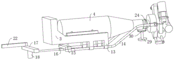
FIG. 1 is a schematic structural diagram of a wind detection system of a wind turbine according to the present invention;
FIG. 2 is a schematic structural diagram of a portion A of FIG. 1 of a wind detection system of a wind turbine according to the present invention;
FIG. 3 is a schematic structural diagram of a portion B in FIG. 1 of a wind detection system of a wind turbine according to the present invention;
FIG. 4 is a schematic view of a nacelle structure of a wind detection system of a wind turbine according to the present invention;
FIG. 5 is a schematic structural view of a rectangular slot box of a wind detection system of a wind turbine according to the present invention;
FIG. 6 is a schematic view of a sliding member of a wind detection system of a wind turbine according to the present invention;
fig. 7 is a schematic structural view of an annular base of a wind power detection system of a wind driven generator according to the present invention.
In the figure: 1. a main shaft; 2. a support frame; 201. a platform; 202. mounting a column; 3. a U-shaped seat; 4. a nacelle; 401. a rectangular notch; 402. a flow baffle plate; 403. a touch bar; 5. a chronic shaft; 6. a gear case; 7. an electric motor; 8. a triangular mounting rack; 9. a fan blade; 10. a sliding sleeve; 11. a rectangular slot box; 1101. a slide hole; 12. an L-shaped clamping plate; 13. connecting lugs; 14. a first pull rod; 15. a first link; 16. a second pull rod; 17. a second link; 18. a connecting shaft; 19. a set square; 20. an L-shaped connecting rod; 21. a connecting pin; 22. a third pull rod; 23. pressing a plate; 24. a first conical tooth; 25. an annular base; 26. a horizontal axis; 27. a first L-shaped support plate; 28. a first worm; 29. a detection member; 30. a second tapered tooth; 31. an adjusting plate; 3101. a tuyere; 32. a drive motor; 33. a worm gear; 34. a gear seat; 35. a second L-shaped support plate; 36. a second worm; 37. a driving gear; 38. a vertical shaft; 39. a slide rail; 40. a spring; 41. and (4) circular rail.
Detailed Description
The technical solutions in the embodiments of the present invention will be clearly and completely described below with reference to the drawings in the embodiments of the present invention, and it is obvious that the described embodiments are only a part of the embodiments of the present invention, and not all of the embodiments.
In the description of the present invention, it is to be understood that the terms "upper", "lower", "front", "rear", "left", "right", "top", "bottom", "inner", "outer", and the like, indicate orientations or positional relationships based on the orientations or positional relationships shown in the drawings, are merely for convenience in describing the present invention and simplifying the description, and do not indicate or imply that the device or element being referred to must have a particular orientation, be constructed and operated in a particular orientation, and thus, should not be construed as limiting the present invention.
Example 1:
referring to fig. 1-7, a wind power detection system of a wind power generator comprises a main shaft 1 and two support frames 2 which are vertically arranged, the two support frames 2 are symmetrically arranged, a platform 201 is fixedly arranged on the upper end face of each support frame 2, an installation column 202 is vertically arranged on each platform 201, a connecting shaft 18 is rotatably arranged in each support frame 2, and the main shaft 1 is in transmission connection with the connecting shaft 18 through a belt.
Inside being hollow structure in the upper end of support frame 2, connecting axle 18 rotates to be installed in hollow structure, and platform 201 is run through out to the upper end of connecting axle 18, sets up the notch that communicates with the external world in the hollow structure department of support frame 2 and is used for the transmission of belt.
It should be noted that the belt transmission is a mechanical transmission, and includes two belt pulleys and a belt tightly sleeved on the two belt pulleys. Two belt pulleys are respectively arranged at the upper ends of the main shaft 1 and the connecting shaft 18, and the friction between the belt and the two belt pulleys is utilized to transmit power.
Referring to fig. 7, further, an annular base 25 fixed on the ground, a horizontal shaft 26 fixedly installed in the annular base 25, a first L-shaped supporting plate 27 fixedly installed on the horizontal shaft 26, and a first worm 28 installed at the lower end of the main shaft 1 penetrating through the first L-shaped supporting plate 27; a driving motor 32 is slidably mounted in the annular base 25, a worm wheel 33 is mounted at the output end of the driving motor 32, and the worm wheel 33 is meshed with the first worm 28.
When the driving motor 32 approaches the first worm 28, the worm wheel 33 at the output end of the driving motor 32 is meshed with the first worm 28 for transmission, so that the first worm 28 drives the spindle 1 to rotate, and the connecting shaft 18 is driven to rotate through the belt.
Further comprising: install U-shaped seat 3 on support frame 2, fixed mounting has the staple bolt on U-shaped seat 3, and the staple bolt passes through the bolt to be installed on erection column 202, through this kind of detachable installation, conveniently remove different aerogenerator on and fix, improved the mobility of whole device. A cabin 4 is installed in the U-shaped seat 3 through bolts, a chronic shaft 5, a gear box 6 and a motor 7 are installed in the cabin 4, a triangular mounting rack 8 is fixedly installed at one end, far away from the cabin 4, of the chronic shaft 5, and fan blades 9 are rotatably installed in the triangular mounting rack 8; a sliding sleeve 10 which is arranged on the chronic shaft 5 in a sliding way, and an adjusting piece is connected between the sliding sleeve 10 and the fan blade 9. A rectangular groove box 11 fixedly arranged on the supporting frame 2, and an L-shaped clamping plate 12 for clamping the U-shaped seat 3 is rotatably arranged in the rectangular groove box 11.
When the wind blows, the wind power lifting fan blades 9 rotate, the rotating fan blades 9 drive the chronic shaft 5 to rotate, the rotating chronic shaft 5 drives the motor 7 to work and generate electricity after being accelerated through the gear box 6, and the L-shaped clamping plates 12 rotatably mounted in the rectangular groove boxes 11 clamp the two sides of the U-shaped seat 3 due to the fact that the motor 7 vibrates in working, and stability of the U-shaped seat 3 mounted on the mounting column 202 is improved.
The adjustment member in this embodiment is further optimized with reference to fig. 1 and 2 and fig. 3 and 6.
The regulating part includes: a triangular plate 19 fixedly installed in the sliding sleeve 10, an L-shaped connecting rod 20 is fixedly installed on the triangular plate 19, a connecting pin 21 is rotatably installed in the L-shaped connecting rod 20, and one end of the connecting pin 21 far away from the L-shaped connecting rod 20 is fixedly connected with the fan blade 9; the connecting lugs 13 are symmetrically arranged below the U-shaped seat 3, the first pull rods 14 are connected in the connecting lugs 13 in a sliding mode, one ends of the symmetrical first pull rods 14 are respectively connected with two sides of the sliding sleeve 10 in a rotating mode, and the other ends of the symmetrical first pull rods 14 are jointly rotatably provided with first connecting rods 15; a second pull rod 16 is rotatably mounted below the first connecting rod 15, one end of the second pull rod 16, which is far away from the first connecting rod 15, is rotatably connected with a second connecting rod 17, and the second connecting rod 17 is fixedly connected with a connecting shaft 18.
When the wind speed changes, the rotation speed of the fan blades 9 changes, at this time, the driving motor 32 approaches the first worm 28 to make the first worm 28 drive the main shaft 1 to rotate, the rotating main shaft 1 drives the connecting shaft 18 to rotate through the belt, the rotating connecting shaft 18 drives the second connecting rod 17 to rotate, the rotating second connecting rod 17 drives the second pull rod 16, the second pull rod 16 drives the first connecting rod 15 and the first pull rod 14 to slide in the connecting lug 13, the sliding first pull rod 14 drives the sliding sleeve 10 to slide on the chronic shaft 5, when the sliding sleeve 10 moves, the L-shaped connecting rod 20 on the triangular plate 19 moves along with the sliding, therefore, the connecting pin 21 rotatably mounted on the L-shaped connecting rod 20 drives the fan blades 9 to change the pitch, so as to keep the stability of the motor 7.
Referring to fig. 5, further, a sliding hole 1101 and a third pull rod 22 sliding in the sliding hole 1101 are disposed on one side of the rectangular slot box 11 close to the nacelle 4, and a pressing plate 23 abutting against the L-shaped clamping plate 12 is fixedly mounted at one end of the third pull rod 22 located in the rectangular slot box 11.
When the second connecting rod 17 rotates, the advancing direction of the third pull rod 22 is opposite to that of the second pull rod 16, the third pull rod 22 extends into the rectangular groove box 11, and the end part of the third pull rod 22 abuts against the pressing plate 23, so that the pressing plate 23 drives the L-shaped clamping plate 12 to rotate, the U-shaped seat 3 is clamped, and the requirement that the clamping is tighter when the wind speed is higher is met.
It should be noted that a vertical shaft 38 is fixedly installed in the rectangular slot box 11, a slide rail 39 is fixedly installed on the vertical shaft 38, the L-shaped clamping plate 12 is rotatably installed on the vertical shaft 38, and one end of the L-shaped clamping plate 12 located in the rectangular slot box 11 is slidably installed on the slide rail 39, so as to provide a guarantee for the stability of the rotation of the L-shaped clamping plate 12;
a spring 40 is arranged in the slide rail 39, and two ends of the spring 40 are respectively fixedly connected with the L-shaped clamping plate 12 and the inner wall of the slide rail 39, so that the L-shaped clamping plate 12 can be conveniently reset.
Referring to fig. 6, further, the first conical tooth 24 is coaxially installed on the chronic shaft 5, the detecting element 29 is fixedly installed below the supporting frame 2, and the detecting element 29 adopts an encoder. The output shaft of the detecting member 29 extends through the support frame 2 and is provided with second conical teeth 30, and the second conical teeth 30 are meshed with the first conical teeth 24.
When the chronic shaft 5 rotates, the first conical teeth 24 on the chronic shaft 5 rotate along with the chronic shaft and transmit the rotating force to the second conical teeth 30, so that the second conical teeth 30 drive the coaxial encoder to work, and the encoder detects the wind power according to the rotating speed and the size of the fan blades 9
Example 2:
referring to fig. 4, basically the same as the embodiment 1, on the basis of the embodiment 1, the whole technical solution is further optimized, and an embodiment of heat dissipation for the nacelle 4 is specifically disclosed.
The wind detection system of the wind turbine in this embodiment further includes: the wind power generation device comprises a rectangular notch 401 arranged on the cabin 4 and an adjusting plate 31 arranged above the rectangular notch 401 in a sliding mode, wherein a flow blocking plate 402 is fixedly arranged on the inner side wall of a groove of the rectangular notch 401, a wind port 3101 is formed in the adjusting plate 31, and the flow blocking plate 402 corresponds to the wind port 3101 at intervals. The baffle plate 402 is fixedly mounted with a contact rod 403, and the contact rod 403 contacts with the L-shaped holding plate 12.
During the operation of the motor 7, the temperature in the cabin 4 rises, and when the U-shaped seat 3 is clamped by the clamping plates of the L-shaped clamping plates 12, the L-shaped clamping plates 12 contact the contact rods 403 and push the contact rods 403, so that the contact rods 403 drive the adjusting plate 31 to slide, a gap is left between the flow blocking plate 402 and the air port 3101, and heat dissipation is facilitated.
When the U-shaped seat 3 is clamped by the L-shaped clamping plate 12, the closer the distance that the regulating plate 31 is driven by the abutting rod 403 to slide is, the larger the gap is left between the flow blocking plate 402 and the air port 3101, and the faster the heat dissipation is.
Example 3:
referring to fig. 1 and 7, basically the same as the embodiment 2, the whole technical solution is further optimized on the basis of the embodiment 2.
The wind detection system of the wind turbine in this embodiment further includes: a gear seat 34 is rotatably arranged on the annular base 25, and the support frame 2 is fixedly arranged on the gear seat 34; a second L-shaped support plate 35 is fixedly mounted on the horizontal shaft 26, a second worm 36 is rotatably mounted in the second L-shaped support plate 35, the upper end of the second worm 36 penetrates through the second L-shaped support plate 35 and is mounted with a driving gear 37, and the driving gear 37 is meshed with the gear seat 34.
When the wind direction is changed, after the driving motor 32 approaches the second worm 36, the worm wheel 33 at the output end of the driving motor 32 is in meshing transmission with the second worm 36, so that the second worm 36 drives the driving gear 37 to rotate, the rotating driving gear 37 drives the gear seat 34 in meshing connection to rotate, the support frame 2 rotates on the ring rail 41, the windward angle of the fan blades 9 is changed, and the rotating speed of the fan blades 9 is optimized.
A wind power detection method of a wind driven generator comprises the following operation steps:
step 1: before detection, symmetrically arranged U-shaped seats 3 are arranged on a support frame 2 through bolts;
step 2: during detection, wind blows the fan blades 9 to rotate, the fan blades 9 drive the chronic shaft 5 to rotate, and the first conical teeth 24 on the chronic shaft 5 drive the second conical teeth 30 in meshed connection to rotate so that the encoder detects the rotating speed of the fan blades 9;
and 3, step 3: when the wind speed changes, the driving motor 32 approaches to the first worm 28, the worm wheel 33 is meshed with the first worm 28 for transmission, the pitch between the fan blades 9 is changed through the adjusting piece, and the encoder detects the rotating speed of the fan blades 9 again;
and 4, step 4: the driving motor 32 approaches the second worm 36, the worm wheel 33 and the second worm 36 are meshed for transmission, the windward angle between the fan blade 9 and the wind direction is changed, the encoder detects the rotating speed of the fan blade 9 again, and the rotating speed of the fan blade 9 is optimized.
The above description is only for the preferred embodiment of the present invention, but the scope of the present invention is not limited thereto, and any person skilled in the art should be considered as the technical solutions and the inventive concepts of the present invention within the technical scope of the present invention.
Claims (10)
1. The utility model provides a aerogenerator's wind-force detecting system, includes main shaft (1) and support frame (2), connecting axle (18) are installed to support frame (2) internal rotation, connect its characterized in that through belt transmission between main shaft (1) and connecting axle (18), still include:
the wind power generator is characterized by comprising a U-shaped seat (3) arranged on a support frame (2), a cabin (4) is arranged in the U-shaped seat (3) through bolts, a chronic shaft (5), a gear box (6) and a motor (7) are arranged in the cabin (4), a triangular mounting frame (8) is fixedly arranged at one end, far away from the cabin (4), of the chronic shaft (5), and fan blades (9) are rotatably arranged in the triangular mounting frame (8);
a sliding sleeve (10) which is slidably arranged on the chronic shaft (5), wherein an adjusting piece is connected between the sliding sleeve (10) and the fan blade (9);
the rectangular groove box (11) is fixedly installed on the support frame (2), and an L-shaped clamping plate (12) for clamping the U-shaped seat (3) is installed in the rectangular groove box (11) in a rotating mode.
2. The wind detection system of a wind turbine according to claim 1, wherein the adjustment member comprises:
the fan blade fixing device comprises a triangular plate (19) fixedly installed in a sliding sleeve (10), wherein an L-shaped connecting rod (20) is fixedly installed on the triangular plate (19), a connecting pin (21) is rotatably installed in the L-shaped connecting rod (20), and one end, far away from the L-shaped connecting rod (20), of the connecting pin (21) is fixedly connected with a fan blade (9);
the connecting lugs (13) are symmetrically arranged below the U-shaped seat (3), first pull rods (14) are connected in the connecting lugs (13) in a sliding mode, one ends of the first pull rods (14) are respectively connected with the two sides of the sliding sleeve (10) in a rotating mode, and first connecting rods (15) are arranged at the other ends of the first pull rods (14) in a rotating mode;
the below of first connecting rod (15) is rotated and is installed second pull rod (16), the one end that first connecting rod (15) were kept away from in second pull rod (16) is rotated and is connected with second connecting rod (17), second connecting rod (17) and connecting axle (18) fixed connection.
3. The wind power detection system of the wind power generator according to claim 2, wherein a sliding hole (1101) and a third pull rod (22) which is matched and slides in the sliding hole (1101) are arranged on one side of the rectangular groove box (11) close to the nacelle (4), and a pressing plate (23) which is abutted to the L-shaped clamping plate (12) is fixedly installed at one end, located in the rectangular groove box (11), of the third pull rod (22).
4. The wind power detection system of the wind power generator according to claim 3, wherein a first conical tooth (24) is coaxially installed on the chronic shaft (5), a detection piece (29) is fixedly installed below the support frame (2), an output shaft of the detection piece (29) penetrates through the support frame (2) and is provided with a second conical tooth (30), and the second conical tooth (30) is meshed with the first conical tooth (24).
5. Wind detection system for wind generators according to claim 4, characterized in that said detection member (29) is an encoder.
6. The wind detection system of a wind turbine according to claim 1, further comprising:
the wind power generation device comprises a rectangular notch (401) arranged on a cabin (4) and an adjusting plate (31) arranged above the rectangular notch (401) in a sliding mode, wherein a flow blocking plate (402) is fixedly arranged on the inner side wall of the groove of the rectangular notch (401), a wind port (3101) is formed in the adjusting plate (31), and the flow blocking plate (402) corresponds to the wind port (3101) at intervals.
7. The wind detecting system of wind power generator according to claim 6, wherein the baffle plate (402) is fixedly installed with a touch bar (403), and the touch bar (403) touches the L-shaped holding plate (12).
8. The wind detection system of a wind turbine according to claim 1, further comprising:
the spindle comprises an annular base (25) fixed on the ground, wherein a horizontal shaft (26) is fixedly installed in the annular base (25), a first L-shaped supporting plate (27) is fixedly installed on the horizontal shaft (26), and the lower end of the spindle (1) penetrates through the first L-shaped supporting plate (27) and is provided with a first worm (28);
sliding mounting has driving motor (32) in annular base (25), worm wheel (33) are installed to the output of driving motor (32), worm wheel (33) are connected with first worm (28) meshing.
9. The wind detection system of a wind power generator according to claim 8, wherein a gear seat (34) is rotatably mounted on the annular base (25), and the support frame (2) is fixedly mounted on the gear seat (34);
fixed mounting has second L shape backup pad (35) on horizontal axis (26), second worm (36) are installed to second L shape backup pad (35) internal rotation, second L shape backup pad (35) are run through and driving gear (37) are installed to the upper end of second worm (36), driving gear (37) are connected with gear seat (34) meshing.
10. A wind detection method of a wind power generator, which adopts a wind detection system of a wind power generator according to any one of claims 1 to 9, characterized by comprising the following operation steps:
step 1: before detection, symmetrically arranged U-shaped seats (3) are arranged on a support frame (2) through bolts;
step 2: during detection, the fan blades (9) are blown by wind power to rotate, the fan blades (9) drive the chronic shaft (5) to rotate, and the first conical teeth (24) positioned on the chronic shaft (5) drive the second conical teeth (30) in meshed connection to rotate so that the encoder detects the rotating speed of the fan blades (9);
and step 3: when the wind speed changes, the driving motor (32) approaches to the first worm (28), the worm wheel (33) is meshed with the first worm (28) for transmission, the pitch between the fan blades (9) is changed through the adjusting piece, the encoder detects the rotating speed of the fan blades (9) again, and the rotating speed of the fan blades (9) is kept stable;
and 4, step 4: the driving motor (32) approaches to the second worm (36), the worm wheel (33) and the second worm (36) are in meshed transmission, the windward angle between the fan blade (9) and the wind direction is changed, the encoder detects the rotating speed of the fan blade (9) again, and the rotating speed of the fan blade (9) is optimized.
Priority Applications (1)
| Application Number | Priority Date | Filing Date | Title |
|---|---|---|---|
| CN202211422421.4A CN115684640A (en) | 2022-11-14 | 2022-11-14 | Wind power detection system and detection method of wind driven generator |
Applications Claiming Priority (1)
| Application Number | Priority Date | Filing Date | Title |
|---|---|---|---|
| CN202211422421.4A CN115684640A (en) | 2022-11-14 | 2022-11-14 | Wind power detection system and detection method of wind driven generator |
Publications (1)
| Publication Number | Publication Date |
|---|---|
| CN115684640A true CN115684640A (en) | 2023-02-03 |
Family
ID=85051969
Family Applications (1)
| Application Number | Title | Priority Date | Filing Date |
|---|---|---|---|
| CN202211422421.4A Pending CN115684640A (en) | 2022-11-14 | 2022-11-14 | Wind power detection system and detection method of wind driven generator |
Country Status (1)
| Country | Link |
|---|---|
| CN (1) | CN115684640A (en) |
Cited By (1)
| Publication number | Priority date | Publication date | Assignee | Title |
|---|---|---|---|---|
| CN117074712A (en) * | 2023-07-21 | 2023-11-17 | 华能国际电力股份有限公司丹东电厂 | A kind of wind power testing equipment for wind power generation |
-
2022
- 2022-11-14 CN CN202211422421.4A patent/CN115684640A/en active Pending
Cited By (1)
| Publication number | Priority date | Publication date | Assignee | Title |
|---|---|---|---|---|
| CN117074712A (en) * | 2023-07-21 | 2023-11-17 | 华能国际电力股份有限公司丹东电厂 | A kind of wind power testing equipment for wind power generation |
Similar Documents
| Publication | Publication Date | Title |
|---|---|---|
| CN112814844A (en) | Wind power generation device with high conversion efficiency and use method thereof | |
| CN107559138A (en) | Wind power generating set with vertical shaft and its variable pitch control method | |
| CN108678905A (en) | A kind of generation of electricity by new energy device | |
| WO2024000160A1 (en) | Wind power generation integrated device for building wind tunnel | |
| CN221074485U (en) | A double-blade wind turbine | |
| CN213775466U (en) | Steam turbine rotor assembling bed | |
| CN106936372B (en) | Wind-solar complementary integrated power generation structure | |
| CN109412514A (en) | A kind of easy-to-mount photovoltaic power generation apparatus of new-energy automobile | |
| CN211082138U (en) | Special direction adjusting mechanism for wind driven generator | |
| CN210222055U (en) | Wind speed detection device for wind power generation | |
| CN201650615U (en) | Two-wheel high-efficiency breeze power generation device | |
| CN215521144U (en) | Wind power detection device of wind driven generator | |
| CN220653269U (en) | A photovoltaic energy storage device | |
| CN115750207B (en) | Overspeed yaw prevention lifting device for wind turbine generator | |
| CN207470349U (en) | A kind of vertical-type wind power plant | |
| CN215378838U (en) | A highly reliable photoelectric bracket for parking garage | |
| CN219509757U (en) | Base device for wind breeze generator | |
| CN216387091U (en) | Wind speed detection device for distributed wind power generation resource assessment | |
| CN215927668U (en) | Fixing device for anemograph based on wind driven generator | |
| CN216477664U (en) | Resistance type and complementary vertical axis wind generating set of lift type | |
| CN222957799U (en) | Mobile device for welding wind power generation component | |
| CN212958942U (en) | Machine head positioning device of small wind driven generator | |
| CN219159107U (en) | Small-sized wind driven generator convenient to install | |
| CN216772266U (en) | Solar cell panel capable of automatically tracking sun | |
| CN211777817U (en) | Impeller assembling table for split installation of wind power plant fan |
Legal Events
| Date | Code | Title | Description |
|---|---|---|---|
| PB01 | Publication | ||
| PB01 | Publication | ||
| SE01 | Entry into force of request for substantive examination | ||
| SE01 | Entry into force of request for substantive examination | ||
| WD01 | Invention patent application deemed withdrawn after publication | ||
| WD01 | Invention patent application deemed withdrawn after publication |
Application publication date: 20230203 |