CN115682057A - Integrated cooker - Google Patents
Integrated cooker Download PDFInfo
- Publication number
- CN115682057A CN115682057A CN202211111341.7A CN202211111341A CN115682057A CN 115682057 A CN115682057 A CN 115682057A CN 202211111341 A CN202211111341 A CN 202211111341A CN 115682057 A CN115682057 A CN 115682057A
- Authority
- CN
- China
- Prior art keywords
- steam
- air
- box
- cooker
- water
- Prior art date
- Legal status (The legal status is an assumption and is not a legal conclusion. Google has not performed a legal analysis and makes no representation as to the accuracy of the status listed.)
- Pending
Links
Images




Landscapes
- Cookers (AREA)
Abstract
本发明提供了一种集成灶,属于厨房设备技术领域。该集成灶包括橱柜、灶具、蒸烤箱设备以及排气部。橱柜开设有开口朝前的容纳腔,容纳腔的上部设置有放置台,放置台对应容纳腔开设有放置孔,灶具嵌入式设置于放置孔中,蒸烤箱设备设置于容纳腔内,排气部包括排蒸汽管、开口朝上的蒸汽进汽盒、开口朝上的接水盒以及蒸汽盖,排蒸汽管的一端与蒸烤箱设备的出气口连通,蒸汽进汽盒设置于灶具的后部上,蒸汽进汽盒的底壁设置有进气嘴,进气嘴与排蒸汽管的另一端连通,接水盒设置于蒸汽进汽盒内,接水盒的底壁设置有进气接口,进气接口的下端部与进气嘴密封式插接,蒸汽盖密封安装于蒸汽进汽盒的上端,蒸汽盖开设有出气孔,出气孔与进气接口错位布置。
The invention provides an integrated stove, which belongs to the technical field of kitchen equipment. The integrated cooker includes a cabinet, a cooker, a steam oven device and an exhaust part. The cabinet is provided with an accommodating cavity with an opening facing forward, and a placing table is arranged on the upper part of the accommodating cavity, and a placing hole is opened corresponding to the accommodating cavity, the stove is embedded in the placing hole, the steam oven equipment is arranged in the accommodating cavity, and the exhaust part It includes a steam exhaust pipe, a steam inlet box with an upward opening, a water receiving box with an upward opening, and a steam cover. One end of the steam exhaust pipe is connected with the air outlet of the steam oven equipment, and the steam inlet box is arranged on the rear of the stove. , the bottom wall of the steam inlet box is provided with an air inlet nozzle, the inlet nozzle communicates with the other end of the steam exhaust pipe, the water receiving box is arranged in the steam inlet box, the bottom wall of the water receiving box is provided with an air inlet interface, The lower end of the air interface is sealed and plugged with the air inlet nozzle, and the steam cover is sealed and installed on the upper end of the steam inlet box.
Description
技术领域technical field
本发明涉及厨房设备技术领域,特别涉及一种集成灶。The invention relates to the technical field of kitchen equipment, in particular to an integrated cooker.
背景技术Background technique
集成化是未来烹饪设备的发展方向,但现有集成灶一般将灶具和蒸箱或烤箱或洗碗机或消毒柜等集成在一起。有以下几个问题:Integration is the development direction of future cooking equipment, but existing integrated stoves generally integrate stoves and steamers or ovens or dishwashers or disinfection cabinets. There are several questions:
1.现有集成灶与厨房整体式橱柜结构、颜色不搭配,不能连为一体,需要断开橱柜台面装配,影响厨房的美感。1. The existing integrated stove does not match the structure and color of the integrated cabinet in the kitchen, and cannot be connected as a whole.
2.现有的集成灶或蒸烤烹饪装置一般的蒸汽排放散热方式为把所产生的剩余蒸汽通过风道由内向外吹,导致厨房空间湿度温度偏高,该蒸汽也会吹向使用者,导致使用者不适。2. The general way of steam exhaust and heat dissipation of existing integrated stoves or steaming and cooking devices is to blow the remaining steam generated from the inside to the outside through the air duct, resulting in high humidity and temperature in the kitchen space, and the steam will also blow to the user. cause discomfort to the user.
发明内容Contents of the invention
本发明的目的在于提供一种集成灶,该集成灶的橱柜型号和款式能够与厨房其他橱柜连成整体式橱柜,提升了整体性和美观性。该集成灶的排气部设置于灶具的后部上并向上排蒸汽或烟气,以被吸油烟机吸入并排出厨房,降低了厨房空间湿度温度,避免了蒸汽吹向使用者的问题发生,提升了用户的烹饪体验。The object of the present invention is to provide an integrated stove, the cabinet model and style of which can be connected with other kitchen cabinets to form an integral cabinet, which improves the integrity and aesthetics. The exhaust part of the integrated cooker is set on the rear of the cooker and discharges steam or smoke upwards, so as to be sucked by the range hood and discharged from the kitchen, which reduces the humidity and temperature of the kitchen space and avoids the problem of steam blowing to the user. Improve the user's cooking experience.
为实现本发明目的,本发明采用如下技术方案:一种集成灶,包括橱柜、灶具、蒸烤箱设备以及排气部。橱柜开设有开口朝前的容纳腔,容纳腔的上部设置有放置台,放置台对应容纳腔开设有放置孔,灶具嵌入式设置于放置孔中,蒸烤箱设备设置于容纳腔内,排气部包括排蒸汽管、开口朝上的蒸汽进汽盒、开口朝上的接水盒以及蒸汽盖,排蒸汽管的一端与蒸烤箱设备的出气口连通,蒸汽进汽盒设置于灶具的后部上,蒸汽进汽盒的底壁设置有进气嘴,进气嘴与排蒸汽管的另一端连通,接水盒设置于蒸汽进汽盒内,接水盒的底壁设置有进气接口,进气接口的下端部与进气嘴密封式插接,蒸汽盖密封安装于蒸汽进汽盒的上端,蒸汽盖开设有出气孔,以向上排蒸汽或烟气,出气孔与进气接口错位布置。In order to achieve the purpose of the present invention, the present invention adopts the following technical solution: an integrated cooker, including a cabinet, a cooker, a steam oven equipment and an exhaust part. The cabinet is provided with an accommodating cavity with an opening facing forward, and a placing platform is arranged on the upper part of the accommodating cavity, and a placing hole is opened corresponding to the accommodating cavity, the stove is embedded in the placing hole, the steam oven equipment is arranged in the accommodating cavity, and the exhaust part It includes a steam exhaust pipe, a steam inlet box with an upward opening, a water receiving box with an upward opening, and a steam cover. One end of the steam exhaust pipe is connected to the air outlet of the steam oven equipment, and the steam inlet box is arranged on the rear of the stove. , the bottom wall of the steam inlet box is provided with an air inlet nozzle, the inlet nozzle communicates with the other end of the steam exhaust pipe, the water receiving box is arranged in the steam inlet box, the bottom wall of the water receiving box is provided with an air inlet interface, The lower end of the air interface is sealed and plugged with the air inlet nozzle. The steam cover is sealed and installed on the upper end of the steam inlet box. The steam cover is provided with an air outlet to discharge steam or smoke upward.
根据本发明的一实施方式,其中,灶具的壳体的后端部开设有卡槽,蒸汽进汽盒设置于卡槽中。According to an embodiment of the present invention, the rear end of the casing of the cooker is provided with a slot, and the steam inlet box is disposed in the slot.
根据本发明的一实施方式,其中,还包括散热部,散热部包括盒体和安装于盒体内的散热风扇,盒体设置于蒸烤箱设备的顶部与灶具之间,盒体的底壁呈之字形,盒体的底壁与蒸烤箱设备的上端之间具有风道,盒体的底壁对应风道开设有第一进风孔,盒体的侧壁开设有出风孔,散热风扇通过风道和第一进风孔抽吸外部冷空气,以对蒸烤箱设备的顶部散热,散热风扇通过出风孔将抽吸的空气排入容纳腔内,以对蒸烤箱设备的两侧以及后部散热。According to an embodiment of the present invention, it further includes a heat dissipation part, the heat dissipation part includes a box body and a cooling fan installed in the box body, the box body is arranged between the top of the steam oven equipment and the cooker, and the bottom wall of the box body is in the shape of There is an air duct between the bottom wall of the box body and the upper end of the steaming oven equipment. The bottom wall of the box body is provided with a first air inlet hole corresponding to the air duct, and the side wall of the box body is provided with an air outlet hole. The air duct and the first air inlet hole draw external cold air to dissipate heat on the top of the steamer, and the cooling fan discharges the sucked air into the accommodating cavity through the air outlet to cool the sides and rear of the steamer. Heat dissipation.
根据本发明的一实施方式,其中,灶具的底壳对应出风孔开设有与容纳腔连通的第二进风孔,散热风扇通过出风孔、容纳腔以及第二进风孔将抽吸的空气排入灶具内并通过灶具排出,以对灶具的内部散热。According to an embodiment of the present invention, wherein the bottom shell of the cooker is provided with a second air inlet hole communicating with the accommodating cavity corresponding to the air outlet hole, and the cooling fan uses the air outlet hole, the accommodating cavity and the second air inlet hole to draw the Air is drawn into and out through the cooker to cool the interior of the cooker.
根据本发明的一实施方式,其中,盒体的两侧壁以及后侧壁均开设有多个出风孔。According to an embodiment of the present invention, a plurality of air outlet holes are opened on both side walls and the rear side wall of the box body.
根据本发明的一实施方式,其中,蒸烤箱设备包括外壳和设置于外壳内的内壳,排蒸汽管的一端与内壳连通,盒体设置于外壳的顶部。According to an embodiment of the present invention, the steam oven equipment includes an outer shell and an inner shell disposed inside the outer shell, one end of the steam exhaust pipe communicates with the inner shell, and the box body is disposed on the top of the outer shell.
根据本发明的一实施方式,其中,蒸烤箱设备还包括水泵、与水泵的吸水口连通的水箱、与水泵的出水口连通的蒸发器、进蒸汽管、水流传感器和电控板,水泵、水箱、水流传感器和电控板均设置于盒体内,蒸发器设置于蒸烤箱设备内,进蒸汽管的一端与蒸发器连通,进蒸汽管的另一端穿过外壳并与内壳连通,以向内壳内输送蒸汽。水流传感器设置于水箱与水泵之间的水管上,以检测水流量,电控板与水流传感器、蒸发器、水泵以及散热风扇电连接。According to an embodiment of the present invention, wherein, the steam oven equipment further includes a water pump, a water tank communicated with the water inlet of the water pump, an evaporator communicated with the water outlet of the water pump, a steam inlet pipe, a water flow sensor and an electric control board, the water pump, the water tank , the water flow sensor and the electric control board are all set in the box body, the evaporator is set in the steam oven equipment, one end of the steam inlet pipe communicates with the evaporator, and the other end of the steam inlet pipe passes through the outer shell and communicates with the inner shell to inwardly Steam is conveyed inside the shell. The water flow sensor is arranged on the water pipe between the water tank and the water pump to detect the water flow, and the electric control board is electrically connected with the water flow sensor, the evaporator, the water pump and the cooling fan.
根据本发明的一实施方式,其中,进气接口的上端延伸至接水盒的腔体内形成防回流结构。According to an embodiment of the present invention, wherein, the upper end of the air inlet port extends into the cavity of the water receiving box to form a backflow prevention structure.
根据本发明的一实施方式,其中,排气部还包括密封圈,密封圈的上端设置有环形外翻边,蒸汽进汽盒与进气嘴可拆卸式连接,进气嘴的腔体内壁开设有环形台阶,密封圈套设于进气嘴的接口内,并且环形外翻边的下端与环形台阶抵接,蒸汽进汽盒的底壁与环形外翻边的上端抵接,进气接口与密封圈密封式插接。According to an embodiment of the present invention, wherein the exhaust part further includes a sealing ring, the upper end of the sealing ring is provided with an annular flange, the steam inlet box is detachably connected to the air inlet nozzle, and the inner wall of the air inlet nozzle cavity is opened There is an annular step, the sealing ring is sleeved in the interface of the air inlet nozzle, and the lower end of the annular outer flange is in contact with the annular step, the bottom wall of the steam inlet box is in contact with the upper end of the annular outer flange, and the air inlet interface is in contact with the sealing Ring-sealed socket.
本发明中的一个实施例具有如下优点或有益效果:An embodiment of the present invention has the following advantages or beneficial effects:
本发明的集成灶,由于包括橱柜、灶具、蒸烤箱设备以及排气部。橱柜的型号和款式能够与厨房其他橱柜连成整体式橱柜,橱柜开设有开口朝前的容纳腔,容纳腔的上部设置有放置台,放置台对应容纳腔开设有放置孔。灶具嵌入式设置于放置台的放置孔中,从而实现了灶具设置于整体式橱柜上,避免了现有的集成灶柜体与整体式橱柜结构和颜色不统一影响厨房美感的问题。蒸烤箱设备设置于容纳腔内,排气部包括排蒸汽管、开口朝上的蒸汽进汽盒、开口朝上的接水盒以及蒸汽盖。排蒸汽管的一端与蒸烤箱设备的出气口连通。蒸汽进汽盒设置于灶具的后部上,蒸汽进汽盒的底壁设置有进气嘴,进气嘴与排蒸汽管的另一端连通。接水盒设置于蒸汽进汽盒内,接水盒的底壁设置有进气接口,进气接口的下端部与进气嘴密封式插接。蒸汽盖密封安装于蒸汽进汽盒的上端,蒸汽盖开设有出气孔,以向上排蒸汽或烟气,以被上方的吸油烟机抽吸排至厨房外。出气孔与进气接口错位布置,防止水蒸气直接排出,以将降低厨房湿度。The integrated cooker of the present invention includes a cabinet, a cooker, a steam oven device and an exhaust part. The model and style of the cabinet can be connected with other cabinets in the kitchen to form an integral cabinet. The cabinet is provided with an accommodating cavity with an opening facing forward. The cooker is embedded in the placement hole of the placing table, so that the cooker is installed on the integral cabinet, and the problem that the structure and color of the existing integrated cooker cabinet and the integral cabinet are not uniform and affects the aesthetics of the kitchen is avoided. The steam oven equipment is arranged in the accommodating cavity, and the exhaust part includes a steam exhaust pipe, a steam inlet box with an upward opening, a water receiving box with an upward opening, and a steam cover. One end of the steam exhaust pipe is communicated with the air outlet of the steam oven equipment. The steam inlet box is arranged on the rear part of the cooker, and the bottom wall of the steam inlet box is provided with an air inlet nozzle, which communicates with the other end of the steam exhaust pipe. The water receiving box is arranged in the steam inlet box, the bottom wall of the water receiving box is provided with an air inlet port, and the lower end of the air inlet port is plugged in a sealed manner with the air inlet nozzle. The steam cover is sealed and installed on the upper end of the steam inlet box, and the steam cover is provided with an air outlet hole to discharge steam or smoke upward, so as to be sucked by the range hood above and discharged out of the kitchen. The air outlet and the air inlet interface are misplaced to prevent the water vapor from being discharged directly, so as to reduce the humidity in the kitchen.
从而在蒸烹饪工作时,蒸烤箱设备内的水蒸气在排蒸汽管的导向下,进入进气嘴,并通过进气接口进入接水盒内,该水蒸气先碰到蒸汽盖,碰到蒸汽盖的水蒸气,一小部分被冷凝形成冷凝水,冷凝水向下滴入接水盒内,而另外一部分的水蒸气会通过出气孔向上排出,以被吸油烟机吸入并排出厨房,降低了厨房空间湿度温度,避免了蒸汽吹向使用者的问题发生,提升了用户的烹饪体验。Therefore, when steaming and cooking, the water vapor in the steam oven equipment enters the air intake nozzle under the guidance of the steam exhaust pipe, and enters the water receiving box through the air intake port. The water vapor first touches the steam cover and then the steam A small part of the water vapor in the cover is condensed to form condensed water, and the condensed water drips down into the water receiving box, while the other part of the water vapor will be discharged upwards through the air outlet to be sucked by the range hood and discharged out of the kitchen, reducing the The humidity and temperature of the kitchen space avoids the problem of steam blowing to the user and improves the cooking experience of the user.
在烤烹饪工作时,蒸烤箱设备内的烟气在排蒸汽管的导向下,进入进气嘴,并通过进气接口进入接水盒内,最后通过出气孔向上排出,以被吸油烟机吸入并排出厨房,避免了烟气聚集在厨房内。During baking and cooking, the smoke in the steam oven is guided by the steam exhaust pipe, enters the air intake nozzle, and enters the water receiving box through the air intake interface, and finally is discharged upwards through the air outlet hole to be sucked by the range hood And out of the kitchen, to avoid the accumulation of smoke in the kitchen.
附图说明Description of drawings
通过参照附图详细描述其示例实施方式,本发明的上述和其它特征及优点将变得更加明显。The above and other features and advantages of the present invention will become more apparent by describing in detail example embodiments thereof with reference to the accompanying drawings.
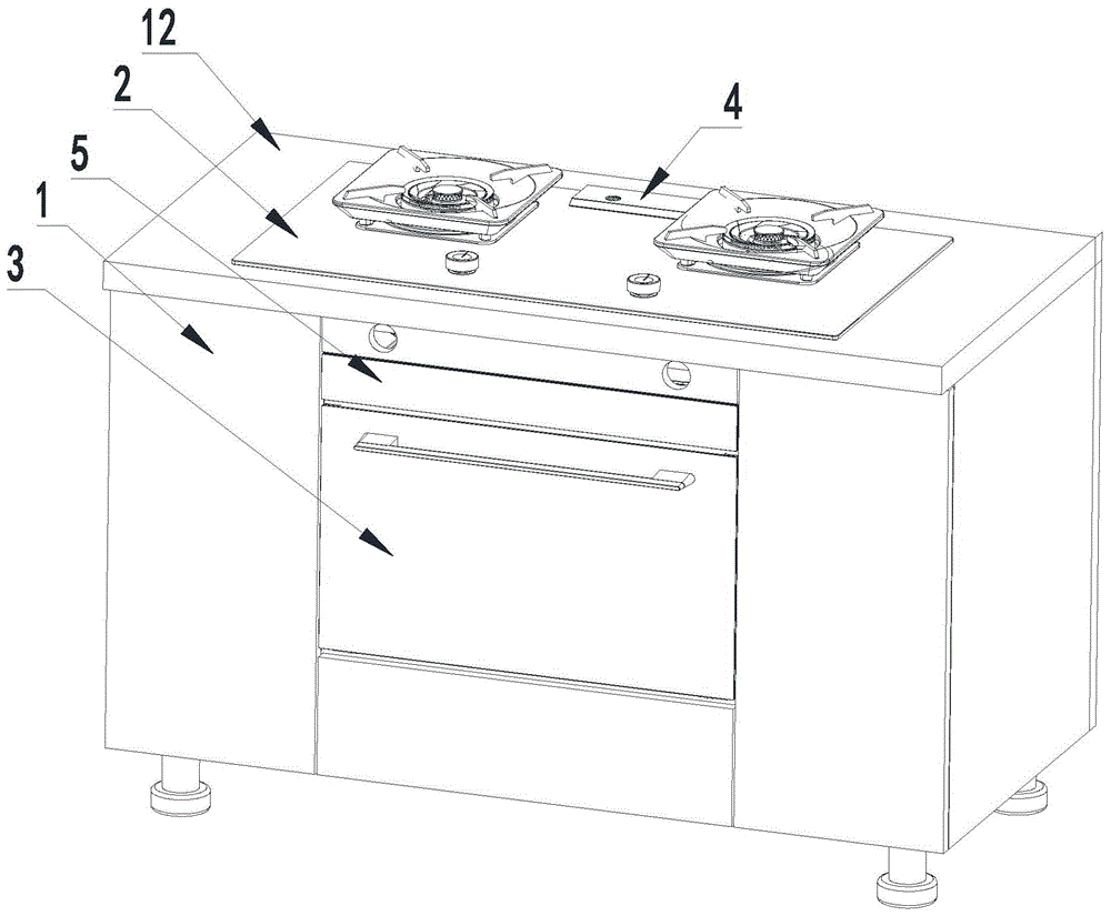
图1是根据一示例性实施方式示出的一种集成灶的立体示意图。Fig. 1 is a schematic perspective view of an integrated stove according to an exemplary embodiment.
图2是根据一示例性实施方式示出的一种集成灶与吸油烟机配合工作的示意图。Fig. 2 is a schematic diagram showing the cooperation of an integrated stove and a range hood according to an exemplary embodiment.
图3是根据一示例性实施方式示出的一种集成灶的灶具与蒸烤箱设备连接示意图。Fig. 3 is a schematic diagram showing a connection between a cooktop of an integrated cooker and a steam oven according to an exemplary embodiment.
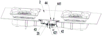
图4是根据一示例性实施方式示出的一种集成灶的排气部的剖视示意图。Fig. 4 is a schematic cross-sectional view of an exhaust part of an integrated cooker according to an exemplary embodiment.
图5是图4的局部放大图。FIG. 5 is a partially enlarged view of FIG. 4 .
图6是根据一示例性实施方式示出的一种集成灶的蒸烤箱设备内的蒸汽进出连接示意图。Fig. 6 is a schematic diagram showing connections of steam in and out in a steam oven device of an integrated cooker according to an exemplary embodiment.
图7是根据一示例性实施方式示出的一种集成灶的橱柜的剖视示意图。Fig. 7 is a schematic cross-sectional view of a cabinet for an integrated stove according to an exemplary embodiment.
图8是图7的局部放大图。FIG. 8 is a partially enlarged view of FIG. 7 .
图9是根据一示例性实施方式示出的一种集成灶的蒸烤箱设备和散热部的立体示意图。Fig. 9 is a schematic perspective view of a steam oven device and a heat dissipation part of an integrated cooker according to an exemplary embodiment.
图10是根据一示例性实施方式示出的一种集成灶的散热部的拆分示意图。Fig. 10 is an exploded schematic diagram of a heat dissipation part of an integrated cooker according to an exemplary embodiment.
图11是根据一示例性实施方式示出的一种集成灶的散热部的内部结构示意图。Fig. 11 is a schematic diagram of the internal structure of a heat dissipation part of an integrated cooker according to an exemplary embodiment.
图12是根据一示例性实施方式示出的一种集成灶的散热部的冷风流向示意图。Fig. 12 is a schematic view showing the cold air flow of the heat dissipation part of an integrated cooker according to an exemplary embodiment.
图13是根据一示例性实施方式示出的一种集成灶的散热部的台阶部的立体示意图。Fig. 13 is a schematic perspective view of a stepped portion of a heat dissipation portion of an integrated cooker according to an exemplary embodiment.
图14是根据一示例性实施方式示出的一种集成灶的散热部的台阶部的侧视示意图。Fig. 14 is a schematic side view of a stepped portion of a heat dissipation portion of an integrated cooker according to an exemplary embodiment.
其中,附图标记说明如下:Wherein, the reference signs are explained as follows:
1、橱柜;11、容纳腔;12、放置台;1. Cabinet; 11. Accommodating cavity; 12. Placement table;
2、灶具;2. Stove;
3、蒸烤箱设备;31、外壳;32、内壳;33、水泵;34、水箱;35、蒸发器;36、进蒸汽管;37、水流传感器;38、电控板;3. Steam oven equipment; 31. Shell; 32. Inner shell; 33. Water pump; 34. Water tank; 35. Evaporator; 36. Inlet steam pipe; 37. Water flow sensor; 38. Electric control board;
4、排气部;41、排蒸汽管;42、蒸汽进汽盒;421、进气嘴;43、接水盒;431、进气接口;44、蒸汽盖;441、出气孔;45、密封圈;4. Exhaust part; 41. Steam exhaust pipe; 42. Steam inlet box; 421. Air inlet nozzle; 43. Water receiving box; 431. Air inlet interface; 44. Steam cover; 441. Air outlet hole; 45. Seal lock up;
5、散热部;51、盒体;511、风道;512、出风孔;513、平板部;514、台阶部;5141、凸缘部;515、翻板;516、前板;52、散热风扇;5. Heat dissipation part; 51. Box body; 511. Air duct; 512. Air outlet hole; 513. Flat plate part; 514. Step part; 5141. Flange part; fan;
6、吸油烟机。6. Range hood.
具体实施方式Detailed ways
现在将参考附图更全面地描述示例实施方式。然而,示例实施方式能够以多种形式实施,且不应被理解为限于在此阐述的实施方式;相反,提供这些实施方式使得本发明将全面和完整,并将示例实施方式的构思全面地传达给本领域的技术人员。图中相同的附图标记表示相同或类似的结构,因而将省略它们的详细描述。Example embodiments will now be described more fully with reference to the accompanying drawings. Example embodiments may, however, be embodied in many forms and should not be construed as limited to the embodiments set forth herein; rather, these embodiments are provided so that this disclosure will be thorough and complete, and will fully convey the concept of example embodiments to those skilled in the art. The same reference numerals in the drawings denote the same or similar structures, and thus their detailed descriptions will be omitted.
用语“一个”、“一”、“该”、“所述”用以表示存在一个或多个要素/组成部分/等;用语“包括”和“具有”用以表示开放式的包括在内的意思并且是指除了列出的要素/组成部分/等之外还可存在另外的要素/组成部分/等。The terms "a", "an", "the", "said" are used to indicate the presence of one or more elements/components/etc; the terms "comprising" and "have" are used to indicate an open-ended inclusion means and means that additional elements/components/etc. may be present in addition to the listed elements/components/etc.
本发明实施例的一种集成灶,将燃气灶和蒸烤箱集成在厨房整体式橱柜上。An integrated cooker according to an embodiment of the present invention integrates a gas cooker and a steam oven into an integrated kitchen cabinet.
当然,不限于上述实施方式,也可以将燃气灶、蒸烤箱以及吸油烟机集成在厨房整体式橱柜上,本领域技术人员可根据实际需要选择集成设备的数量。Of course, it is not limited to the above-mentioned embodiment, and the gas stove, the steam oven and the range hood can also be integrated on the integrated kitchen cabinet, and those skilled in the art can select the number of integrated devices according to actual needs.
具体地,如图1至图14所示,一种集成灶,包括橱柜1、灶具2、蒸烤箱设备3以及排气部4。Specifically, as shown in FIGS. 1 to 14 , an integrated cooker includes a
橱柜1的型号和款式能够与厨房其他橱柜连成整体式橱柜,橱柜1开设有开口朝前的容纳腔11,容纳腔11的上部设置有放置台12,放置台12对应容纳腔11开设有放置孔。The model and style of the
灶具2嵌入式设置于放置台12的放置孔中,从而实现了灶具2设置于整体式橱柜上,避免了现有的集成灶柜体与整体式橱柜结构和颜色不统一影响厨房美感的问题。The
蒸烤箱设备3设置于容纳腔11内,并且,当蒸烤箱设备3的门体关闭后封闭容纳腔11。The
排气部4包括排蒸汽管41、开口朝上的蒸汽进汽盒42、开口朝上的接水盒43以及蒸汽盖44。The exhaust part 4 includes a
排蒸汽管41的一端与蒸烤箱设备3的出气口连通。One end of the
蒸汽进汽盒42设置于灶具2的后部上,蒸汽进汽盒42的底壁设置有进气嘴421,进气嘴421与排蒸汽管41的另一端连通。The
接水盒43设置于蒸汽进汽盒42内,接水盒43的底壁设置有进气接口431,进气接口431的下端部与进气嘴421密封式插接。The
蒸汽盖44密封安装于蒸汽进汽盒42的上端,蒸汽盖44开设有出气孔441,以向上排蒸汽或烟气,以被上方的吸油烟机6抽吸排至厨房外。The
出气孔441与进气接口431错位布置,防止水蒸气直接排出,以降低厨房湿度。The
优选出气孔441与蒸汽进汽盒42的侧壁与接水盒43的侧壁之间的空腔对应。Preferably, the
接水盒43的侧壁的上端沿开设有凹槽,以使蒸汽从接水盒43进入与出气孔441对应的空腔内,并通过出气孔441排出。The upper end of the side wall of the
在蒸烹饪工作时,蒸烤箱设备3内的水蒸气在排蒸汽管41的导向下,进入进气嘴421,并通过进气接口431进入接水盒43内,该水蒸气先碰到蒸汽盖44,碰到蒸汽盖44的水蒸气,一小部分被冷凝形成冷凝水,冷凝水向下滴入接水盒43内,而另外一部分的水蒸气会通过出气孔441向上排出,以被吸油烟机6吸入并排出厨房,降低了厨房空间湿度温度,避免了蒸汽吹向使用者的问题发生,提升了用户的烹饪体验。When steaming and cooking, the water vapor in the
在烤烹饪工作时,蒸烤箱设备3内的烟气在排蒸汽管41的导向下,进入进气嘴421,并通过进气接口431进入接水盒43内,最后通过出气孔441向上排出,以被吸油烟机吸入并排出厨房,避免了烟气聚集在厨房内。During the cooking operation, the smoke in the
如图1至图14相关各图所示,在本发明的一个优选实施例中,灶具2的壳体的后端部开设有卡槽,蒸汽进汽盒42设置于卡槽中。As shown in the relevant figures of FIG. 1 to FIG. 14 , in a preferred embodiment of the present invention, a slot is provided at the rear end of the housing of the
例如,蒸汽进汽盒42的上端设置有环形外翻边,蒸汽进汽盒42的主体设置在卡槽中,环形外翻边的下端面与灶具2的面板的上端面抵接并固定,蒸汽盖44密封安装于环形外翻边的上端面。For example, the upper end of the
如图1至图14相关各图所示,在本发明的一个优选实施例中,进气接口431的上端延伸至接水盒43的腔体内形成防回流结构,防止冷凝水回流至蒸烤箱设备3内,避免了影响食物的口味。As shown in Figures 1 to 14, in a preferred embodiment of the present invention, the upper end of the
如图1至图14相关各图所示,优选蒸汽盖44为透明盖板,以便于观察冷凝水量。当观察到接水盒43内的察冷凝水将要满时,可拆下蒸汽盖44,将接水盒43拔出以倒掉冷凝水即可。As shown in the relevant figures of FIGS. 1 to 14 , preferably the
如图1至图14相关各图所示,在本发明的一个优选实施例中,排气部4还包括密封圈45,密封圈45的上端设置有环形外翻边。As shown in the relevant figures of FIGS. 1 to 14 , in a preferred embodiment of the present invention, the exhaust part 4 further includes a sealing
如图1至图14相关各图所示,蒸汽进汽盒42与进气嘴421可拆卸式连接,进气嘴421的腔体内壁开设有环形台阶,密封圈45套设于进气嘴421的接口内,并且环形外翻边的下端与环形台阶抵接,蒸汽进汽盒42的底壁与环形外翻边的上端抵接。As shown in Figures 1 to 14, the
接水盒43的进气接口431与密封圈45密封式插接,从而实现了接水盒43在拔出或插接时,避免了密封圈45轴向运动导致密封失效的问题发生。The
如图1至图14相关各图所示,在本发明的一个优选实施例中,还包括散热部5,散热部5包括盒体51和安装于盒体51内的散热风扇52。As shown in FIGS. 1 to 14 , in a preferred embodiment of the present invention, a
盒体51设置于蒸烤箱设备3的顶部与灶具2之间,盒体51的底壁呈之字形,盒体51的底壁与蒸烤箱设备3的上端之间具有风道511。The
盒体51的底壁对应风道511开设有第一进风孔,盒体51的侧壁开设有出风孔512,散热风扇52通过风道511和第一进风孔抽吸外部冷空气,以带走蒸烤箱设备3的顶部和灶具2辐射产生的热量。The bottom wall of the
散热风扇52通过出风孔512将抽吸的空气排入容纳腔11内,以对蒸烤箱设备3的两侧以及后部散热。The cooling
如图1至图14相关各图所示,在本发明的一个优选实施例中,灶具2的底壳对应出风孔512开设有与容纳腔11连通的第二进风孔,散热风扇52通过出风孔512、容纳腔11以及第二进风孔将抽吸的空气排入灶具2内并通过灶具2排出,以对灶具2的内部散热。As shown in Figures 1 to 14, in a preferred embodiment of the present invention, the bottom shell of the
如图12所示,外部A区域的冷空气,在散热风扇的作用下,被抽进烹饪装置的顶部风道511处的B区域,直至吸入散热风扇52。As shown in FIG. 12 , the cold air in the outer area A is sucked into area B at the
冷空气从散热风扇52出来后,伴随着空气压力,通过出风孔512吹入容纳腔11内。After the cold air comes out from the cooling
容纳腔11内的一部分冷空气通过橱柜1的空隙(密封不严情况下)吹出,另一部分冷空气通过灶具2的底壳上的第二进风孔吹入灶具2内,最后通过灶具2的旋钮下端的间隙、燃烧器的间隙处进入厨房环境,该流动空气对灶具2内部的阀体、炉头、显示器等部件进行了散热,降低了灶具的内部温升,防止灶具2内的阀体、控制器和其他电子器件在高温下工作不稳定的情况发生。A part of the cold air in the
盒体51的两侧壁以及后侧壁均开设有多个出风孔512。Two sidewalls and a rear sidewall of the
如图1至图14相关各图所示,在本发明的一个优选实施例中,盒体51的底壁包括平板部513和与平板部513的前部固接的台阶部514,盒体51的截面呈之字形,风道511由台阶部514和蒸烤箱设备3的上端面围设形成。As shown in Figures 1 to 14, in a preferred embodiment of the present invention, the bottom wall of the
如图13和图14所示,在本发明的一个优选实施例中,台阶部514前低后高且前宽后窄,散热风扇52安装于台阶部514的后部上。As shown in FIG. 13 and FIG. 14 , in a preferred embodiment of the present invention, the stepped
台阶部514前低后高且前宽后窄,作用是增加入风后的面积和体积,可以有效降低进风口的噪音。前宽(M端)后窄(N端)的结构,增加了入气口的面积,在散热风扇52一定的转速的情况下,有效增加入风量。采用前低(M端)后高(N端)的逐步过渡的结构,可以提高进风量以及令到风在风道的流动更加顺畅,降低冷空气的运动噪音以及降低风能的损失。The
优选的,台阶部514的设置有凸缘部5141以及环绕凸缘部5141的安装柱,散热风扇52固定于安装柱上,并且散热风扇52的下端与凸缘部5141的上端抵接,以进一步增加了风扇进风口的体积,有利于降低风噪以及提高进风量。Preferably, the stepped
如图1至图14相关各图所示,在本发明的一个优选实施例中,盒体51的前侧设置有可启闭的翻板515,以便于维护或更换盒体5内的部件。As shown in Figures 1 to 14, in a preferred embodiment of the present invention, an openable and
优选的,还包括与翻板515传动连接的驱动装置,以实现自动开启或关闭。Preferably, it also includes a driving device that is in transmission connection with the
盒体51的两侧壁以及后侧壁均开设有多个出风孔512,以利于散热风扇52吹出的风通过三侧的散热孔进入蒸烤箱设备3外侧。Both side walls and the rear side wall of the
翻板515与蒸烤箱设备3之间且对应风道511设置有前板516,前板516开设有多个第三进风孔,以使外部空气进入风道511内。A
如图1至图14相关各图所示,在本发明的一个优选实施例中,蒸烤箱设备3包括外壳31和设置于外壳31内的内壳32,排蒸汽管41的一端与内壳32连通,盒体51设置于外壳31的顶部。As shown in Figures 1 to 14, in a preferred embodiment of the present invention, the
如图1至图14相关各图所示,在本发明的一个优选实施例中,蒸烤箱设备3还包括水泵33、与水泵33的吸水口连通的水箱34、与水泵33的出水口连通的蒸发器35、进蒸汽管36、水流传感器37和电控板38,水泵33和水箱34均设置于盒体51内,蒸发器35设置于蒸烤箱设备3内,进蒸汽管36的一端与蒸发器35连通,进蒸汽管36的另一端穿过外壳31并与内壳32连通,以向内壳32内输送蒸汽。As shown in Figures 1 to 14, in a preferred embodiment of the present invention, the
优选的,水箱34设置在台阶部514上。Preferably, the
水流传感器37设置于水箱34与水泵33之间的水管上,以检测水流量,电控板38与水流传感器37、蒸发器35、水泵33以及散热风扇52电连接。The
如图12所示,冷空气从散热风扇52出来后,会分别吹向C、D、E三个区域。As shown in FIG. 12 , after the cold air comes out from the cooling
冷空气吹向三个区域的过程中,冷空气经过了水泵33、电控板38、内部线、水流传感器37以及电源线等电器部件,在把蒸烤箱设备3顶部的热量带走的同时,降低了水泵33、电控板38、内部线、水流传感器37以及电源线的表面温度。During the process of blowing the cold air to the three areas, the cold air passes through electrical components such as the
B、C、D区域位于橱柜1内部,蒸烤箱设备3的外侧,灶具2的底部,而进入B、C、D区域的流动空气,因为有空气压力,一部分流动空气会从蒸烤箱设备3的四周前端或橱柜1的间隙流出,并带走蒸烤箱设备3和灶具2产生的热量,降低集成灶整个系统内部的温升。Areas B, C, and D are located inside the
而进入B、C、D区域的流动空气,另一部分会通过灶具2底壳的孔,进入灶具2内部,最后通过灶具2的旋钮下端的间隙、燃烧器的间隙处进入厨房环境,该流动空气对灶具2内部的阀体、炉头、显示器等部件进行了散热,降低了灶具的内部温升,防止灶具2内的阀体、控制器和其他电子器件在高温下工作不稳定的情况发生。The other part of the flowing air entering areas B, C, and D will enter the interior of the
在本发明实施例中,术语“多个”则指两个或两个以上,除非另有明确的限定。术语“安装”、“连接”、“固定”等术语均应做广义理解,例如,“连接”可以是固定连接,也可以是可拆卸连接,或一体地连接。对于本领域的普通技术人员而言,可以根据具体情况理解上述术语在本发明实施例中的具体含义。In the embodiments of the present invention, the term "multiple" refers to two or more, unless otherwise clearly defined. Terms such as "installation", "connection" and "fixation" should be interpreted broadly, for example, "connection" can be a fixed connection, a detachable connection, or an integral connection. Those of ordinary skill in the art can understand the specific meanings of the above terms in the embodiments of the present invention according to specific situations.
本发明实施例的描述中,需要理解的是,术语“上”、“下”等指示的方位或位置关系为基于附图所示的方位或位置关系,仅是为了便于描述本发明实施例和简化描述,而不是指示或暗示所指的装置或单元必须具有特定的方向、以特定的方位构造和操作,因此,不能理解为对本发明实施例的限制。In the description of the embodiments of the present invention, it should be understood that the orientations or positional relationships indicated by the terms "upper" and "lower" are based on the orientations or positional relationships shown in the drawings, and are only for the convenience of describing the embodiments of the present invention and The description is simplified, but does not indicate or imply that the referred device or unit must have a specific direction, be constructed and operated in a specific orientation, and therefore, should not be construed as limiting the embodiments of the present invention.
在本说明书的描述中,术语“一个实施例”、“一个优选实施例”等的描述意指结合该实施例或示例描述的具体特征、结构、材料或特点包含于本发明实施例的至少一个实施例或示例中。在本说明书中,对上述术语的示意性表述不一定指的是相同的实施例或实例。而且,描述的具体特征、结构、材料或特点可以在任何的一个或多个实施例或示例中以合适的方式结合。In the description of this specification, the description of the terms "one embodiment", "one preferred embodiment" and the like means that the specific features, structures, materials or characteristics described in conjunction with the embodiment or example are included in at least one of the embodiments of the present invention Examples or examples. In this specification, schematic representations of the above terms do not necessarily refer to the same embodiment or example. Furthermore, the specific features, structures, materials or characteristics described may be combined in any suitable manner in any one or more embodiments or examples.
以上仅为本发明实施例的优选实施例而已,并不用于限制本发明实施例,对于本领域的技术人员来说,本发明实施例可以有各种更改和变化。凡在本发明实施例的精神和原则之内,所作的任何修改、等同替换、改进等,均应包含在本发明实施例的保护范围之内。The above are only preferred embodiments of the embodiments of the present invention, and are not intended to limit the embodiments of the present invention. For those skilled in the art, various modifications and changes may be made to the embodiments of the present invention. Any modifications, equivalent replacements, improvements, etc. made within the spirit and principle of the embodiments of the present invention shall be included in the protection scope of the embodiments of the present invention.
Claims (10)
Priority Applications (1)
| Application Number | Priority Date | Filing Date | Title |
|---|---|---|---|
| CN202211111341.7A CN115682057A (en) | 2022-09-13 | 2022-09-13 | Integrated cooker |
Applications Claiming Priority (1)
| Application Number | Priority Date | Filing Date | Title |
|---|---|---|---|
| CN202211111341.7A CN115682057A (en) | 2022-09-13 | 2022-09-13 | Integrated cooker |
Publications (1)
| Publication Number | Publication Date |
|---|---|
| CN115682057A true CN115682057A (en) | 2023-02-03 |
Family
ID=85062801
Family Applications (1)
| Application Number | Title | Priority Date | Filing Date |
|---|---|---|---|
| CN202211111341.7A Pending CN115682057A (en) | 2022-09-13 | 2022-09-13 | Integrated cooker |
Country Status (1)
| Country | Link |
|---|---|
| CN (1) | CN115682057A (en) |
Cited By (3)
| Publication number | Priority date | Publication date | Assignee | Title |
|---|---|---|---|---|
| CN117029053A (en) * | 2023-09-20 | 2023-11-10 | 杭州老板电器股份有限公司 | A waterproof structure and integrated stove |
| CN117814598A (en) * | 2023-09-20 | 2024-04-05 | 杭州老板电器股份有限公司 | Integrated component and integrated stove |
| WO2025025668A1 (en) * | 2023-07-28 | 2025-02-06 | 广东合胜厨电科技有限公司 | Integrated stove having cooking device |
Citations (8)
| Publication number | Priority date | Publication date | Assignee | Title |
|---|---|---|---|---|
| CN106724769A (en) * | 2016-12-17 | 2017-05-31 | 浙江美大实业股份有限公司 | A kind of integrated kitchen range with electric steam box |
| CN110207221A (en) * | 2018-10-30 | 2019-09-06 | 华帝股份有限公司 | Integrated stove with heat dissipation device |
| CN210124742U (en) * | 2019-04-30 | 2020-03-06 | 九阳股份有限公司 | Dish washing machine |
| CN111503668A (en) * | 2019-01-30 | 2020-08-07 | 宁波方太厨具有限公司 | Integrated stove with cooking device |
| CN211913150U (en) * | 2020-02-12 | 2020-11-13 | 河南久之盛智能科技有限公司 | Waste gas purification environmental protection equipment |
| CN212855278U (en) * | 2020-08-06 | 2021-04-02 | 江西永宁科技有限责任公司 | Tail gas processing apparatus of sodium perchlorate production usefulness |
| CN214332807U (en) * | 2020-09-30 | 2021-10-01 | 宁波方太厨具有限公司 | Integrated kitchen |
| CN218269199U (en) * | 2022-09-13 | 2023-01-10 | 华帝股份有限公司 | Integrated kitchen range |
-
2022
- 2022-09-13 CN CN202211111341.7A patent/CN115682057A/en active Pending
Patent Citations (8)
| Publication number | Priority date | Publication date | Assignee | Title |
|---|---|---|---|---|
| CN106724769A (en) * | 2016-12-17 | 2017-05-31 | 浙江美大实业股份有限公司 | A kind of integrated kitchen range with electric steam box |
| CN110207221A (en) * | 2018-10-30 | 2019-09-06 | 华帝股份有限公司 | Integrated stove with heat dissipation device |
| CN111503668A (en) * | 2019-01-30 | 2020-08-07 | 宁波方太厨具有限公司 | Integrated stove with cooking device |
| CN210124742U (en) * | 2019-04-30 | 2020-03-06 | 九阳股份有限公司 | Dish washing machine |
| CN211913150U (en) * | 2020-02-12 | 2020-11-13 | 河南久之盛智能科技有限公司 | Waste gas purification environmental protection equipment |
| CN212855278U (en) * | 2020-08-06 | 2021-04-02 | 江西永宁科技有限责任公司 | Tail gas processing apparatus of sodium perchlorate production usefulness |
| CN214332807U (en) * | 2020-09-30 | 2021-10-01 | 宁波方太厨具有限公司 | Integrated kitchen |
| CN218269199U (en) * | 2022-09-13 | 2023-01-10 | 华帝股份有限公司 | Integrated kitchen range |
Cited By (4)
| Publication number | Priority date | Publication date | Assignee | Title |
|---|---|---|---|---|
| WO2025025668A1 (en) * | 2023-07-28 | 2025-02-06 | 广东合胜厨电科技有限公司 | Integrated stove having cooking device |
| CN117029053A (en) * | 2023-09-20 | 2023-11-10 | 杭州老板电器股份有限公司 | A waterproof structure and integrated stove |
| CN117814598A (en) * | 2023-09-20 | 2024-04-05 | 杭州老板电器股份有限公司 | Integrated component and integrated stove |
| CN117029053B (en) * | 2023-09-20 | 2025-11-28 | 杭州老板电器股份有限公司 | A waterproof structure and an integrated stove |
Similar Documents
| Publication | Publication Date | Title |
|---|---|---|
| CN218269199U (en) | Integrated kitchen range | |
| CN111503668B (en) | Integrated stove with cooking device | |
| CN111503672B (en) | An integrated stove with cooking appliances | |
| WO2022100117A1 (en) | Embedded cooking appliance and cooking system | |
| WO2021115105A1 (en) | Cooking electric appliance with microwave heating function | |
| CN113464988B (en) | An integrated stove | |
| CN114383156A (en) | Integrated cooking stove | |
| CN210107489U (en) | Integrated stove with cooking device | |
| CN111503669B (en) | Integrated stove with cooking device | |
| CN218269180U (en) | Integrated kitchen range | |
| CN115875694A (en) | Integrated kitchen with cooking device | |
| CN111503670B (en) | Integrated stove with cooking device | |
| CN217004550U (en) | Integrated cooking stove | |
| CN112361397B (en) | Cooking equipment and cooking system | |
| CN218936424U (en) | Heat radiation structure for integrated kitchen | |
| CN217274302U (en) | Gas stove and integrated stove with cooking device | |
| CN111853874B (en) | Integrated stove with cooking device | |
| CN218237549U (en) | Cooking device and integrated kitchen | |
| CN210399024U (en) | Integrated kitchen with cooking device | |
| CN216079908U (en) | Integrated kitchen with cooking device | |
| CN115435343A (en) | Integrated kitchen range | |
| CN115682055A (en) | Cooking device and integrated kitchen | |
| CN111503671B (en) | Integrated stove with cooking device | |
| CN205332284U (en) | Built -in cooking appliance | |
| CN103807886B (en) | Micro-wave oven |
Legal Events
| Date | Code | Title | Description |
|---|---|---|---|
| PB01 | Publication | ||
| PB01 | Publication | ||
| SE01 | Entry into force of request for substantive examination | ||
| SE01 | Entry into force of request for substantive examination | ||
| RJ01 | Rejection of invention patent application after publication |
Application publication date: 20230203 |
|
| RJ01 | Rejection of invention patent application after publication |