CN115673787A - Special portable right angle mills machine - Google Patents
Special portable right angle mills machine Download PDFInfo
- Publication number
- CN115673787A CN115673787A CN202211560131.6A CN202211560131A CN115673787A CN 115673787 A CN115673787 A CN 115673787A CN 202211560131 A CN202211560131 A CN 202211560131A CN 115673787 A CN115673787 A CN 115673787A
- Authority
- CN
- China
- Prior art keywords
- axis
- platform
- sliding table
- screw rod
- nut
- Prior art date
- Legal status (The legal status is an assumption and is not a legal conclusion. Google has not performed a legal analysis and makes no representation as to the accuracy of the status listed.)
- Pending
Links
- 238000003801 milling Methods 0.000 claims abstract description 66
- 230000007704 transition Effects 0.000 claims description 12
- 238000003825 pressing Methods 0.000 claims description 10
- 238000003754 machining Methods 0.000 description 10
- 238000000034 method Methods 0.000 description 7
- 238000010586 diagram Methods 0.000 description 2
- 238000005553 drilling Methods 0.000 description 2
- 210000004907 gland Anatomy 0.000 description 2
- 239000002184 metal Substances 0.000 description 2
- 230000009286 beneficial effect Effects 0.000 description 1
- 238000012986 modification Methods 0.000 description 1
- 230000004048 modification Effects 0.000 description 1
- 238000005498 polishing Methods 0.000 description 1
Images


Landscapes
- Machine Tool Units (AREA)
Abstract
The invention discloses a movable right-angle milling special machine device which comprises an X-axis base, a nut platform, a Z-axis platform, a right-angle milling head and a motor mechanism, wherein the nut platform is arranged on the X-axis base; the X-axis base is provided with a first sliding rail, an X-axis screw rod and a nut platform, and the X-axis screw rod drives the nut platform to slide left and right along the X axis; a second sliding rail, a Y-axis sliding table and a Y-axis adjusting screw rod are mounted on the nut platform, the Y-axis sliding table is mounted on the nut platform and slides back and forth along the Y axis, and a self-locking block and the Y-axis adjusting screw rod are mounted at one end of the Y-axis platform; a Z-axis platform is vertically arranged on one side of the Y-axis sliding table, a third sliding rail, a Z-axis sliding table and a Z-axis adjusting screw rod are arranged on the Z-axis platform, and the Z-axis sliding table is arranged on the Z-axis platform and slides up and down along the Z axis; and a motor mechanism and a right-angle milling head are arranged on the Z-axis sliding table. The special machine device extends into the inner surface of a workpiece to complete milling of the included angle, the root and the narrow slit area of the workpiece, the right-angle milling head is configured with milling power and is directly connected with the motor, the special machine occupies small space, the operation is flexible and convenient, and the product quality and the efficiency are improved.
Description
Technical Field
The invention belongs to the technical field of machining of metal cutting, and particularly relates to a movable right-angle special milling machine device.
Background
At present, in metal milling machining, for a machined workpiece with a special surface, such as the inner surface, the middle, narrow gaps and included angle areas of the workpiece, the machining cannot be finished on a common machine tool, necessary milling machining cannot be carried out due to the fact that a milling head of the common machine tool cannot extend into the inner surface of the workpiece, and the traditional method adopts bench workers for polishing and drilling a mold to carry out simple machining treatment. The milling head device of the machine tool has a series of problems that the inner surface of a machined workpiece, a narrow slit and an included angle area are narrow, the milling head device of the machine tool cannot machine the surface of the workpiece, or the manual machining quality is not high, the product percent of pass is low, the efficiency is low, and the quality cannot be guaranteed for some products with high requirements.
Aiming at the mechanical processing with special requirements, the problem that the existing common machine tool cannot process workpieces with narrow slits and dead angle areas is solved, and a special machine for processing the inner surfaces, the middle parts, the included angles and the narrow slits of the workpieces is developed and used for processing the procedures of plane milling, drilling, groove milling, back chipping and the like, and meanwhile, the product quality can be improved, the labor intensity of workers is reduced, and the problem is urgently needed to be solved at present.
Disclosure of Invention
The invention aims to solve the problems that the existing milling cannot process the included angle, the root part and the narrow slit area of a workpiece, a milling head of a common machine tool cannot extend into the machine tool or cannot extend into the machine tool to complete the processing, a bench worker cannot complete the manual processing procedure, the quality of a manually processed product is low, the efficiency is low, and the common machine tool is difficult to carry for processing due to too large workpiece.
In order to solve the technical problems, the invention adopts the technical scheme that: the utility model provides a portable right angle mills special machine, its characterized in that: the device comprises an X-axis base, a nut platform, a Z-axis platform, a right-angle milling head and a motor mechanism;
the X-axis base is provided with a first sliding rail, an X-axis screw rod and a nut platform, the X-axis base is provided with a positioning plate and sleeved with the X-axis screw rod, a nut is arranged below the nut platform and sleeved with the X-axis screw rod, and the X-axis screw rod drives the nut platform to slide left and right along an X axis;
the screw platform is provided with a second sliding rail, a Y-axis sliding table and a Y-axis adjusting screw rod, the Y-axis sliding table is arranged on the screw platform and slides back and forth along the Y axis, one end of the Y-axis platform is provided with a self-locking block and is sleeved with the Y-axis adjusting screw rod, the Y-axis adjusting screw rod is fastened on the side surface of the Y-axis sliding table, first sliding table pressing covers are arranged on the two sides of the Y-axis sliding table and the screw platform, and a first locking screw rod is arranged on the Y-axis sliding table and is fastened with the screw platform;
a Z-axis platform is vertically arranged on one side of the Y-axis sliding table, a third sliding rail, a Z-axis sliding table and a Z-axis adjusting screw rod are arranged on the Z-axis platform, the Z-axis sliding table is arranged on the Z-axis platform and slides up and down along the Z axis, a second self-locking block is arranged at one end of the Z-axis platform and sleeved with the Z-axis adjusting screw rod, the Z-axis adjusting screw rod is fastened on the side surface of the Z-axis sliding table, second sliding table pressing covers are arranged on the Z-axis sliding table and two sides of the Z-axis platform, and a second locking screw rod is arranged on the Z-axis sliding table and fastened with the Z-axis platform;
the Z-axis sliding table is provided with a transition seat, the transition seat is provided with a motor mechanism, and the motor mechanism is provided with a right-angle milling head.
Preferably, a hand wheel is installed at one end of the X-axis screw rod.
Preferably, a first sliding groove is arranged below the nut platform and sleeved on the first sliding rail and slides on the X-axis base, a second sliding groove is arranged below the Y-axis sliding table and sleeved on the second sliding rail and slides on the nut platform, and a third sliding groove is arranged below the Z-axis sliding table and sleeved on the third sliding rail and slides on the Z-axis platform.
Preferably, the Z-axis platform reverse side mounting support plate is fastened on the Y-axis sliding table.
Preferably, the motor mechanism and the right-angle milling head are arranged on two sides of the transition seat.
The invention has the beneficial effects that:
1. according to the movable special right-angle milling machine device, the nut platform, the Z-axis platform, the right-angle milling head and the motor mechanism are mounted on the X-axis base, the position of the right-angle milling head is adjusted in a sliding mode through the sliding tables in the X-axis direction, the Y-axis direction and the Z-axis direction, and the special right-angle milling machine is compact in structure and is fixedly mounted on a workpiece, so that the purpose of processing a region which is difficult to process by a common machine tool and aims at narrow gaps and small included angles and is large in size in the thickness direction can be specially achieved.
2. According to the movable special right-angle milling machine device, the three platforms of the X-axis, the Y-axis and the Z-axis, which are formed by the X-axis base, the nut platform and the Z-axis platform, are simply connected, so that the X-axis base of the special right-angle milling machine is positioned and fastened on a plane in a workpiece, under the condition that power is met, the narrow gap and the narrow space of an included angle area of the workpiece are fully considered, the size of the special machine is reduced as much as possible, the distance from the horizontal axis of the angle milling head to a processing surface is reduced, the adaptability of the special machine is improved, on the other hand, the weight of the special right-angle milling machine device is reduced, the working intensity of manual operation is reduced, and the special right-angle milling machine device is also suitable for the working condition that the workpiece is too large and inconvenient to process on a common machine tool.
3. According to the movable right-angle special milling machine device, the screw platform and the two sides of the Y-axis sliding table are provided with the first sliding table pressing covers, so that the Y-axis sliding table is pressed on the screw platform, one end of the Y-axis platform is provided with the self-locking block and is sleeved with the Y-axis adjusting screw rod, meanwhile, the Z-axis platform and the two sides of the Z-axis sliding table are provided with the second sliding table pressing covers, so that the Z-axis sliding table is pressed on the Z-axis sliding table, one end of the Z-axis platform is provided with the self-locking block and is sleeved with the Z-axis adjusting screw rod, the adjustment and locking of the screw rod in the Y-axis direction and the Z-axis direction are respectively completed, and the positioning and fastening of a special machine are completed to perform milling.
4. According to the movable special right-angle milling machine device, the transition seat is installed on the Z-axis sliding table, the motor mechanism and the right-angle milling head are installed on the transition seat, the power for milling the right-angle milling head is configured with the direct-connected motor to drive the right-angle milling head, milling output can be completed, and the special machine is simple in structure and light and convenient to operate; the motor mechanism and the right-angle milling head are inversely hung on the Z-axis platform, so that the occupied space of the special angle milling machine is compressed as much as possible, the height of the whole special angle milling machine can be reduced to the greatest extent, the included angle, the root and the narrow slit area of a milling workpiece are finished, the milling head of a common machine tool cannot extend into the special angle milling machine or extend into the special angle milling machine tool to still not finish machining, and a bench worker cannot finish the manual machining process.
Drawings
FIG. 1 is a schematic structural diagram of a movable right-angle special milling machine device of the invention;
FIG. 2 is a schematic sectional view of a Y-axis sliding table and a nut platform of the movable special right-angle milling machine device;
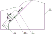
FIG. 3 is a schematic diagram of a movable right-angle milling machine device for processing a workpiece according to the invention.
The automatic milling machine comprises a 1-X-axis base, a 2-sliding rail I, a 3-X-axis screw rod, a 4-positioning plate, a 5-hand wheel, a 6-Y-axis adjusting screw rod, a 7-self-locking block I, an 8-nut platform, a 9-Y-axis sliding table, a 10-sliding table gland I, a 11-locking screw rod I, a 12-right-angle milling head, a 13-transition seat, a 14-Z-axis adjusting screw rod, a 15-self-locking block II, a 16-Z-axis sliding table, a 17-Z-axis platform, an 18-motor mechanism, a 19-supporting plate, a 20-nut, a 21-sliding groove I, a 22-sliding rail II, a 23-sliding groove II, a 24-sliding table gland II, a 25-locking screw rod II and a 26-workpiece.
Detailed Description
For a better understanding, the invention is further described below with reference to specific examples.
Referring to fig. 1, 2 and 3, the invention provides a movable right-angle special milling machine device. The special machine device comprises an X-axis base 1, a nut platform 8 is arranged on the X-axis base 1, a Z-axis platform 17 is arranged on the side surface of the nut platform 8, a Z-axis sliding table, a motor mechanism 18 and a right-angle milling head 12 are arranged on the Z-axis platform 17, and the X-axis base 1, the nut platform 8 and the Z-axis platform 17 are used for guiding and positioning the right-angle milling head through the X-axis platform, the Y-axis platform and the Z-axis platform 17.
A first sliding rail 2 and a positioning plate 4 are arranged on an X-axis base 1, an X-axis screw rod 3 is arranged on the X-axis base 1 along the X-axis direction, one end of the X-axis screw rod 3 is sleeved into the positioning plate 4, a nut platform 8 is arranged at the other end of the X-axis screw rod 3, a nut 20 is arranged below the nut platform 8, the X-axis screw rod 3 is sleeved with the nut 20, a first sliding groove 21 is formed below the nut platform 8, the nut platform 8 is sleeved on the first sliding rail 2 through the first sliding groove 21, the nut platform 8 is arranged on the first sliding rail 2 and can slide left and right, the X-axis screw rod 3 drives the nut platform 8 to slide left and right on the X-axis base 1 along the X-axis direction, and a hand wheel 5 is arranged at one end of the X-axis screw rod 3.
A second sliding rail 22, a Y-axis sliding table 9 and a Y-axis adjusting screw rod 6 are arranged on a nut platform 8, a second sliding groove 23 is formed below the Y-axis sliding table 9, the Y-axis sliding table 9 is sleeved on the second sliding rail 22 through the second sliding groove 23, the Y-axis sliding table 9 is arranged on the second sliding rail 22 and can slide back and forth, the Y-axis sliding table 9 is arranged on the nut platform 8 and can slide back and forth along a Y axis, a first self-locking block 7 is arranged at one end of the Y-axis platform, the Y-axis adjusting screw rod 6 is sleeved on the first self-locking block 7, the top end of the Y-axis adjusting screw rod 6 is fastened on the side face of the Y-axis sliding table 9, first sliding table pressing covers 10 are arranged on two sides of the Y-axis sliding table 9 and the nut platform 8, the Y-axis sliding table 9 and the nut platform 8 are fastened through fastening bolts on the first sliding table pressing covers 10, a kidney-shaped hole is formed in the Y-axis sliding table 9, and the first locking screw rod 11 fastens the Y-axis sliding table 9 and the nut platform 8 through the kidney-shaped hole.
A Z-axis platform 17 is vertically arranged on one side face of a Y-axis sliding table 9, a third sliding rail, a Z-axis sliding table 16 and a Z-axis adjusting screw rod 14 are arranged on the Z-axis platform 17, a third sliding groove is formed below the Z-axis sliding table 16, the Z-axis sliding table 16 is sleeved on the third sliding rail through the third sliding groove, the Z-axis sliding table 16 is arranged on the third sliding rail and can slide up and down along the Z axis, the Z-axis sliding table 16 is arranged on the Z-axis platform 17 and can slide up and down along the Z axis, a second self-locking block 15 is arranged at one end of the Z-axis platform 17, the Z-axis adjusting screw rod 14 is sleeved on the second self-locking block 15, the top end of the Z-axis adjusting screw rod 14 is fastened on the side face of the Z-axis sliding table 16, second sliding table pressing covers 24 are arranged on two sides of the Z-axis sliding table 16 and the Z-axis platform 17, fastening bolts are arranged on the second sliding table pressing covers 24 to fasten the Y-axis sliding table 9 and the Z-axis platform 17, kidney-shaped holes are formed in the Z-axis sliding table 16, and the second locking screws 25 fasten the Z-axis sliding table 16 and the Z-axis sliding table platform 17 through the kidney-axis sliding table.
A transition seat 13 is formed on a Z-axis sliding table 16 or the transition seat 13 is installed, a motor mechanism 18 which is a motor and a motor shaft is installed on the transition seat 13, a right-angle milling head 12 is installed on the motor mechanism 18, the right-angle milling head 12 is installed on the motor shaft, and the motor mechanism 18 and the right-angle milling head 12 are respectively installed on two sides of the transition seat 13.
When a special machine device is used for machining a workpiece 26, the X-axis base is integrally positioned and fastened on a plane in the workpiece 26, a nut platform 8 and a component are installed, and finally a Z-axis platform 17 and a component are installed; when the angle milling machine is operated, any two of the X-axis direction, the Y-axis direction and the Z-axis direction, such as the Y-axis sliding table 9 or the Z-axis sliding table 16, are kept in a positioning and fastening mode, then one lead screw or hand wheel 5 is manually adjusted, and after the lead screw or hand wheel is electrified, the direct connection motor drives the angle milling head to drive the special angle milling machine to mill; and any one sliding table in the directions of an X axis, a Y axis and a Z axis can be positioned and fastened, then two screw rods such as a Y axis adjusting screw rod 6, a Z axis adjusting screw rod 14 or a hand wheel 5 are manually adjusted, the positioning setting and locking of front and back, left and right and up and down movement of the machining requirements are met, and a direct-connected motor drives an angle milling head to drive the right-angle special milling machine to mill.
The embodiments of the present invention have been described in detail, but the description is only for the preferred embodiments of the present invention and should not be construed as limiting the scope of the present invention. All equivalent changes and modifications made within the scope of the present invention should be covered by the present patent.
Claims (5)
1. The utility model provides a special machine equipment is milled to portable right angle which characterized in that: the device comprises an X-axis base, a nut platform, a Z-axis platform, a right-angle milling head and a motor mechanism;
the X-axis base is provided with a first sliding rail, an X-axis screw rod and a nut platform, the X-axis base is provided with a positioning plate and sleeved with the X-axis screw rod, a nut is arranged below the nut platform and sleeved with the X-axis screw rod, and the X-axis screw rod drives the nut platform to slide left and right along the X axis;
the screw platform is provided with a second sliding rail, a Y-axis sliding table and a Y-axis adjusting screw rod, the Y-axis sliding table is arranged on the screw platform and slides back and forth along the Y axis, one end of the Y-axis platform is provided with a self-locking block and is sleeved with the Y-axis adjusting screw rod, the Y-axis adjusting screw rod is fastened on the side surface of the Y-axis sliding table, first sliding table pressing covers are arranged on the two sides of the Y-axis sliding table and the screw platform, and a first locking screw rod is arranged on the Y-axis sliding table and is fastened with the screw platform;
a Z-axis platform is vertically arranged on one side of the Y-axis sliding table, a third sliding rail, a Z-axis sliding table and a Z-axis adjusting screw rod are arranged on the Z-axis platform, the Z-axis sliding table is arranged on the Z-axis platform and slides up and down along the Z axis, a second self-locking block is arranged at one end of the Z-axis platform and sleeved with the Z-axis adjusting screw rod, the Z-axis adjusting screw rod is fastened on the side surface of the Z-axis sliding table, second sliding table pressing covers are arranged on the Z-axis sliding table and two sides of the Z-axis platform, and a second locking screw rod is arranged on the Z-axis sliding table and fastened with the Z-axis platform;
the Z-axis sliding table is provided with a transition seat, the transition seat is provided with a motor mechanism, and the motor mechanism is provided with a right-angle milling head.
2. The mobile right angle milling machine apparatus of claim 1, wherein: and a hand wheel is arranged at one end of the X-axis screw rod.
3. The mobile right angle milling machine apparatus of claim 1, wherein: the screw platform is characterized in that a first sliding groove sleeve is arranged below the screw platform and is arranged on a first sliding rail and slides on the X-axis base, a second sliding groove sleeve is arranged below the Y-axis sliding table and is arranged on a second sliding rail and slides on the screw platform, and a third sliding groove sleeve is arranged below the Z-axis sliding table and is arranged on a third sliding rail and slides on the Z-axis platform.
4. The portable right angle milling machine apparatus of claim 1, wherein: and a supporting plate is arranged on the reverse side of the Z-axis platform and fastened on the Y-axis sliding table.
5. The mobile right angle milling machine apparatus of claim 1, wherein: the motor mechanism and the right-angle milling head are arranged on two sides of the transition seat.
Priority Applications (2)
| Application Number | Priority Date | Filing Date | Title |
|---|---|---|---|
| CN202211560131.6A CN115673787A (en) | 2022-12-07 | 2022-12-07 | Special portable right angle mills machine |
| CN202320498596.7U CN219786672U (en) | 2022-12-07 | 2023-03-15 | Movable right-angle milling special machine device |
Applications Claiming Priority (1)
| Application Number | Priority Date | Filing Date | Title |
|---|---|---|---|
| CN202211560131.6A CN115673787A (en) | 2022-12-07 | 2022-12-07 | Special portable right angle mills machine |
Publications (1)
| Publication Number | Publication Date |
|---|---|
| CN115673787A true CN115673787A (en) | 2023-02-03 |
Family
ID=85056514
Family Applications (2)
| Application Number | Title | Priority Date | Filing Date |
|---|---|---|---|
| CN202211560131.6A Pending CN115673787A (en) | 2022-12-07 | 2022-12-07 | Special portable right angle mills machine |
| CN202320498596.7U Active CN219786672U (en) | 2022-12-07 | 2023-03-15 | Movable right-angle milling special machine device |
Family Applications After (1)
| Application Number | Title | Priority Date | Filing Date |
|---|---|---|---|
| CN202320498596.7U Active CN219786672U (en) | 2022-12-07 | 2023-03-15 | Movable right-angle milling special machine device |
Country Status (1)
| Country | Link |
|---|---|
| CN (2) | CN115673787A (en) |
-
2022
- 2022-12-07 CN CN202211560131.6A patent/CN115673787A/en active Pending
-
2023
- 2023-03-15 CN CN202320498596.7U patent/CN219786672U/en active Active
Also Published As
| Publication number | Publication date |
|---|---|
| CN219786672U (en) | 2023-10-03 |
Similar Documents
| Publication | Publication Date | Title |
|---|---|---|
| CN208992409U (en) | Double-station modularization sanding and polishing lathe | |
| CN110774378B (en) | Multifunctional numerical control woodworking machine tool | |
| CN211332176U (en) | Working table of gantry planing and milling machine | |
| CN210099062U (en) | Workbench of shaper | |
| CN216327528U (en) | Double-end centre bore grinds machine | |
| CN212551910U (en) | Positioning device of numerical control milling machine | |
| CN206763939U (en) | Differential mechanism four sides boring machine tool | |
| CN220388608U (en) | Milling equipment for metal product production and processing | |
| CN111001859B (en) | Controllable sliding structure of planer type milling machine | |
| CN211804803U (en) | Vertical and horizontal combined machining equipment | |
| CN218696374U (en) | A positioning fixture for CNC gantry milling machine processing | |
| CN219786672U (en) | Movable right-angle milling special machine device | |
| CN218639116U (en) | Chamfering tool of vertical milling machine | |
| CN214350870U (en) | Turnover workbench | |
| CN111843036A (en) | A new type of sawing machine | |
| CN215698266U (en) | Numerical control engraving and milling machine with lifting adjusting function | |
| CN215942117U (en) | Movable boring device | |
| CN215749665U (en) | Numerical control drilling device | |
| CN214920788U (en) | Embedded sliding seat milling machine structure | |
| CN105922373B (en) | A kind of horizontal both-end subtracts tenon machine | |
| CN213288819U (en) | A double-head multi-function tool-changing end-milling CNC milling machine | |
| CN210254422U (en) | An F-type rail multi-station gantry milling machine | |
| CN211306617U (en) | Multifunctional numerical control woodworking machine tool | |
| CN220330156U (en) | Movable column type planer milling machine for milling oil pipe threads | |
| CN222059491U (en) | Milling flutes machine tool |
Legal Events
| Date | Code | Title | Description |
|---|---|---|---|
| PB01 | Publication | ||
| PB01 | Publication | ||
| WD01 | Invention patent application deemed withdrawn after publication |
Application publication date: 20230203 |
|
| WD01 | Invention patent application deemed withdrawn after publication |