CN115669309A - Automatic punching device - Google Patents
Automatic punching device Download PDFInfo
- Publication number
- CN115669309A CN115669309A CN202211428829.2A CN202211428829A CN115669309A CN 115669309 A CN115669309 A CN 115669309A CN 202211428829 A CN202211428829 A CN 202211428829A CN 115669309 A CN115669309 A CN 115669309A
- Authority
- CN
- China
- Prior art keywords
- bearing plate
- lifting
- automatic punching
- water tank
- motor
- Prior art date
- Legal status (The legal status is an assumption and is not a legal conclusion. Google has not performed a legal analysis and makes no representation as to the accuracy of the status listed.)
- Pending
Links
Images


Classifications
-
- Y—GENERAL TAGGING OF NEW TECHNOLOGICAL DEVELOPMENTS; GENERAL TAGGING OF CROSS-SECTIONAL TECHNOLOGIES SPANNING OVER SEVERAL SECTIONS OF THE IPC; TECHNICAL SUBJECTS COVERED BY FORMER USPC CROSS-REFERENCE ART COLLECTIONS [XRACs] AND DIGESTS
- Y02—TECHNOLOGIES OR APPLICATIONS FOR MITIGATION OR ADAPTATION AGAINST CLIMATE CHANGE
- Y02P—CLIMATE CHANGE MITIGATION TECHNOLOGIES IN THE PRODUCTION OR PROCESSING OF GOODS
- Y02P70/00—Climate change mitigation technologies in the production process for final industrial or consumer products
- Y02P70/10—Greenhouse gas [GHG] capture, material saving, heat recovery or other energy efficient measures, e.g. motor control, characterised by manufacturing processes, e.g. for rolling metal or metal working
Landscapes
- Cultivation Receptacles Or Flower-Pots, Or Pots For Seedlings (AREA)
Abstract
本发明公开了一种自动打孔装置,涉及植树机械技术领域,本发明包括移动装置、支撑装置以及升降装置,移动装置包括转动轮以及履带,转动轮一侧表面与履带内部一侧表面连接,支撑装置包括承重板、水箱、阀门以及散热箱,承重板中部设有圆孔,水箱下表面与承重板上表面连接,阀门一侧表面与水箱下端出水口一侧表面连接,散热箱下表面与承重板上表面连接,散热箱内部设有第一电机,升降装置包括固定架、弹簧杆以及升降板组成的升降组件。本发明一种自动打孔装置,第一电机控制主动轴转动带动整个装置的移动,第二电机控制弹簧杆推动打孔机位置的移动,相比传统打孔装置,整体结构较少,操作简单,便于家庭植树使用,较为方便。
The invention discloses an automatic punching device, which relates to the technical field of tree planting machinery. The invention includes a moving device, a supporting device and a lifting device. The moving device includes a rotating wheel and a track. One side surface of the turning wheel is connected to the inner side surface of the track. The supporting device includes a load-bearing plate, a water tank, a valve and a heat dissipation box. A round hole is provided in the middle of the load-bearing plate. The lower surface of the water tank is connected with the upper surface of the load-bearing plate. The upper surface of the bearing plate is connected, the first motor is arranged inside the cooling box, and the lifting device includes a lifting assembly composed of a fixed frame, a spring rod and a lifting plate. The invention is an automatic punching device. The first motor controls the rotation of the driving shaft to drive the movement of the whole device, and the second motor controls the spring rod to push the position of the punching machine. Compared with the traditional punching device, the overall structure is less and the operation is simple. , It is convenient for family tree planting to use, more convenient.
Description
技术领域technical field
本发明涉及植树机械技术领域,特别涉及一种自动打孔装置。The invention relates to the technical field of tree planting machinery, in particular to an automatic punching device.
背景技术Background technique
栽植苗木的营林机械。一般由机架、苗箱、牵引或悬挂装置、开沟或挖坑器、植苗机构、递苗装置、覆土压实装置、传动机构、起落机构等组成。作业时,开沟器在林地上开出植树沟或穴,用人工或植苗机构按一定株距将树苗投放到沟(穴)中,然后由覆土压实装置将苗木根部土壤覆盖压实。Forestry machinery for planting seedlings. It is generally composed of a frame, a seedling box, a traction or suspension device, a ditching or digging device, a seedling planting mechanism, a seedling delivery device, a soil compacting device, a transmission mechanism, a lifting mechanism, etc. During operation, the ditch opener opens a tree planting ditch or hole on the forest land, and the saplings are put into the ditch (hole) at a certain spacing by manual or seedling planting mechanism, and then the soil at the root of the seedling is covered and compacted by the soil compacting device.
现在已知的植树机整体较大,操作较为困难,且使用时噪音较大,不适用于家庭植树活动,为此设计一种自动打孔装置来解决上述问题。The present known tree planting machine is overall larger, more difficult to operate, and louder in use, and is not suitable for family tree planting activities. For this reason, a kind of automatic punching device is designed to solve the above problems.
发明内容Contents of the invention
本发明的目的在于提供一种自动打孔装置,克服了现有技术的不足,通过第一电机控制履带转动带动整个装置在土上移动,第二电机控制打孔机的上下移动,具有人工劳作较少、工作效率高、操作简单的特点。The purpose of the present invention is to provide an automatic punching device, which overcomes the deficiencies of the prior art. The first motor controls the rotation of the crawler to drive the whole device to move on the soil, and the second motor controls the up and down movement of the punching machine, which has the advantages of manual labor. Less, high work efficiency and simple operation.
为解决上述问题,本发明所采取的技术方案如下:In order to solve the above problems, the technical scheme adopted in the present invention is as follows:
一种自动打孔装置,包括An automatic punching device, comprising
移动装置,包括转动轮以及履带,所述转动轮一侧表面与履带内部一侧表面连接;The mobile device includes a rotating wheel and a track, and one side surface of the turning wheel is connected to the inner side surface of the track;
支撑装置,包括承重板、水箱、阀门以及散热箱,所述承重板中部设有圆孔,所述水箱下表面与承重板上表面连接,所述阀门一侧表面与水箱下端出水口一侧表面连接,所述散热箱下表面与承重板上表面连接,所述散热箱内部设有第一电机;The support device includes a load-bearing plate, a water tank, a valve, and a cooling tank. A round hole is provided in the middle of the load-bearing plate. The lower surface of the water tank is connected to the upper surface of the load-bearing plate. connected, the lower surface of the cooling box is connected to the upper surface of the bearing plate, and a first motor is arranged inside the cooling box;
升降装置,包括固定架、弹簧杆以及升降板组成的升降组件,所述固定架内部两侧表面均设有滑槽,所述固定架下表面与承重板上表面连接,所述弹簧杆上端与固定架内部下表面连接,所述弹簧杆下表面与升降板上表面连接,所述升降板两侧表面分别与两个滑槽内部一侧表面连接。The lifting device includes a lifting assembly composed of a fixed frame, a spring rod and a lifting plate. Both sides of the internal surface of the fixed frame are provided with slide grooves. The lower surface of the fixed frame is connected to the upper surface of the bearing plate. The upper end of the spring rod is connected to The inner lower surface of the fixed frame is connected, the lower surface of the spring rod is connected with the upper surface of the lifting plate, and the two side surfaces of the lifting plate are connected with the inner side surfaces of the two chute respectively.
进一步,所述移动装置还包括主动轴以及从动轴,所述主动轴以及从动轴一侧表面均与转动轮内部一侧表面连接,所述第一电机输出轴穿过承重板上表面与主动轴一侧表面连接。Further, the moving device also includes a driving shaft and a driven shaft, the side surfaces of the driving shaft and the driven shaft are connected to the inner side surface of the rotating wheel, and the output shaft of the first motor passes through the upper surface of the bearing plate and Surface connection on one side of the drive shaft.
进一步,所述移动装置还包括限位环,所述限位环内部一侧表面与主动轴一侧表面连接,所述限位环内部一侧表面与从动轴一侧表面连接。Further, the moving device further includes a limit ring, an inner surface of the limit ring is connected to a surface of the driving shaft, and an inner surface of the limit ring is connected to a surface of the driven shaft.
进一步,所述支撑装置还包括推杆、照明灯以及放置盒,所述推杆下端与承重板上表面连接,所述照明灯一侧表面与承重板一侧表面连接,所述放置盒下表面与承重板上表面连接。Further, the support device also includes a push rod, a lighting lamp and a placement box, the lower end of the push rod is connected to the upper surface of the bearing plate, the side surface of the lighting lamp is connected to the side surface of the bearing plate, and the lower surface of the placement box is Connect to the upper surface of the bearing plate.
进一步,所述支撑装置还包括进水口,所述进水口下端与水箱上表面连接。Further, the supporting device further includes a water inlet, the lower end of which is connected to the upper surface of the water tank.
进一步,所述升降装置还包括第二电机,所述第二电机下表面与固定架上表面连接。Further, the lifting device further includes a second motor, and the lower surface of the second motor is connected to the upper surface of the fixing frame.
进一步,所述升降装置还包括打孔机,所述打孔机上端与升降板下表面连接。Further, the lifting device also includes a punching machine, the upper end of which is connected to the lower surface of the lifting plate.
本发明与现有技术相比较,具有以下有益效果:Compared with the prior art, the present invention has the following beneficial effects:
本发明通过设置主动轴带动履带的转动,便于整个装置在植树地的移动,防止卡陷在泥土中。The invention drives the rotation of the caterpillar by setting the driving shaft, which facilitates the movement of the whole device in the tree planting field and prevents it from being stuck in the soil.
本发明通过在承重板上设置阀门连接的水箱,直接连接水管水植树坑内进行浇水,保证树苗的存活。In the present invention, a water tank connected by a valve is arranged on the load-bearing plate, and the water pipe is directly connected to water the tree planting pit to ensure the survival of the saplings.
本发明通过设置弹簧杆带动升降板控制打孔机的运作对土地进行打孔,减少了人工劳作。In the present invention, a spring rod is set to drive a lifting plate to control the operation of a punching machine to punch holes in the land, thereby reducing manual labor.
本发明具有人工劳作较少、工作效率高、操作简单的特点。The invention has the characteristics of less manual labor, high work efficiency and simple operation.
附图说明Description of drawings
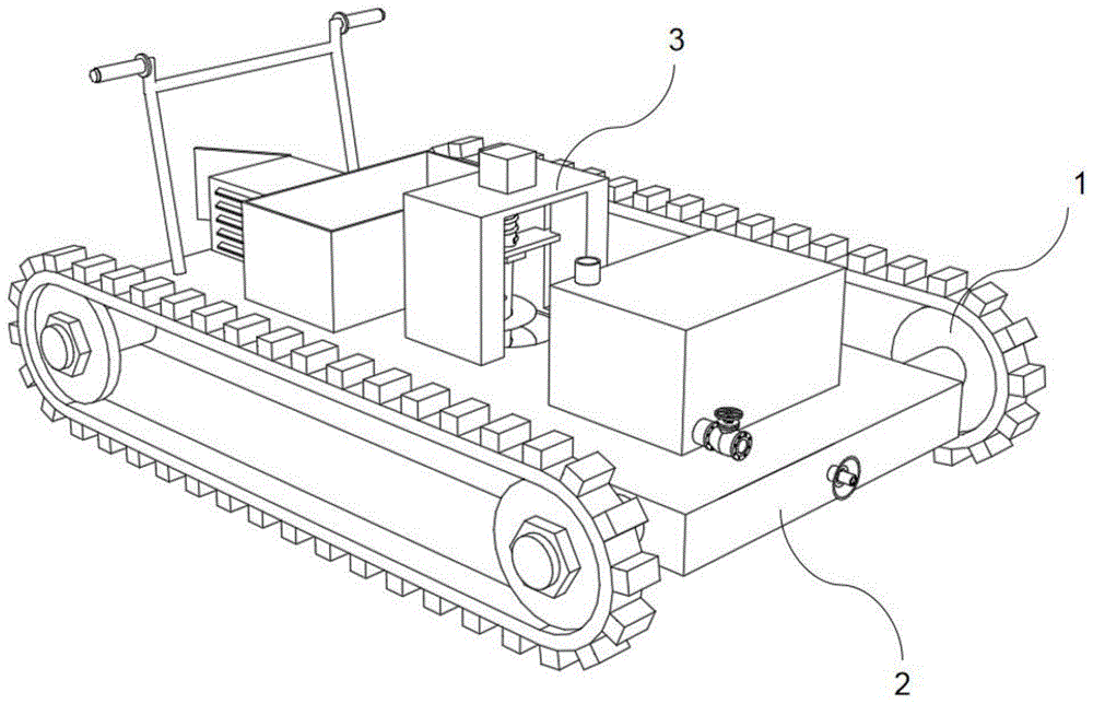
图1为一种自动打孔装置的外部整体结构示意图;Fig. 1 is a schematic diagram of the external overall structure of an automatic punching device;
图2为一种自动打孔装置的移动装置结构示意图;Fig. 2 is a structural schematic diagram of a mobile device of an automatic punching device;
图3为一种自动打孔装置的支撑装置结构示意图;Fig. 3 is a structural schematic diagram of a supporting device of an automatic punching device;
图4为一种自动打孔装置的升降装置结构示意图;Fig. 4 is a structural schematic diagram of a lifting device of an automatic punching device;
图中:1、移动装置;101、主动轴;102、限位环;103、转动轮;104、履带;105、从动轴;2、支撑装置;201、承重板;202、推杆;203、水箱;204、进水口;205、阀门;206、照明灯;207、放置盒;208、散热箱;3、升降装置;301、第二电机;302、固定架;303、弹簧杆;304、升降板;305、打孔机。Among the figure: 1, moving device; 101, driving shaft; 102, limit ring; 103, running wheel; 104, crawler belt; 105, driven shaft; 2, supporting device; 201, bearing plate; 202, push rod; 203 , water tank; 204, water inlet; 205, valve; 206, lighting lamp; 207, placement box; 208, cooling box; 3, lifting device; 301, second motor; 302, fixed frame; Lifting plate; 305, punching machine.
具体实施方式Detailed ways
为使本发明实现的技术手段、创作特征、达成目的与功效易于明白了解,下面结合具体实施方式,进一步阐述本发明。In order to make the technical means, creative features, goals and effects achieved by the present invention easy to understand, the present invention will be further described below in conjunction with specific embodiments.
在本发明的描述中,需要说明的是,术语“上”、“下”、“内”、“外”“前端”、“后端”、“两端”、“一端”、“另一端”等指示的方位或位置关系为基于附图所示的方位或位置关系,仅是为了便于描述本发明和简化描述,而不是指示或暗示所指的装置或元件必须具有特定的方位、以特定的方位构造和操作,因此不能理解为对本发明的限制。此外,术语“第一”、“第二”仅用于描述目的,而不能理解为指示或暗示相对重要性。In the description of the present invention, it should be noted that the terms "upper", "lower", "inner", "outer", "front end", "rear end", "both ends", "one end", "another end" The orientation or positional relationship indicated by etc. is based on the orientation or positional relationship shown in the drawings, which is only for the convenience of describing the present invention and simplifying the description, rather than indicating or implying that the referred device or element must have a specific orientation, use a specific Azimuth configuration and operation, therefore, should not be construed as limiting the invention. In addition, the terms "first" and "second" are used for descriptive purposes only, and should not be understood as indicating or implying relative importance.
在本发明的描述中,需要说明的是,除非另有明确的规定和限定,术语“安装”、“设置有”、“连接”等,应做广义理解,例如“连接”,可以是固定连接,也可以是可拆卸连接,或一体地连接;可以是机械连接,也可以是电连接;可以是直接相连,也可以通过中间媒介间接相连,可以是两个元件内部的连通。对于本领域的普通技术人员而言,可以具体情况理解上述术语在本发明中的具体含义。In the description of the present invention, it should be noted that, unless otherwise specified and limited, the terms "installed", "set with", "connected", etc. should be understood in a broad sense, such as "connected", which may be a fixed connection , can also be detachably connected, or integrally connected; can be mechanically connected, can also be electrically connected; can be directly connected, can also be indirectly connected through an intermediary, and can be internal communication between two components. Those of ordinary skill in the art can understand the specific meanings of the above terms in the present invention in specific situations.
请参照图1—4所示,本发明为一种自动打孔装置,包括Please refer to shown in Fig. 1-4, the present invention is a kind of automatic punching device, comprises
移动装置1,包括转动轮103以及履带104,转动轮103一侧表面与履带104内部一侧表面连接;The mobile device 1 includes a rotating
支撑装置2,包括承重板201、水箱203、阀门205以及散热箱208,承重板201中部设有圆孔,水箱203下表面与承重板201上表面连接,阀门205一侧表面与水箱203下端出水口一侧表面连接,散热箱208下表面与承重板201上表面连接,散热箱208内部设有第一电机;The supporting
升降装置3,包括固定架302、弹簧杆303以及升降板304组成的升降组件,固定架302内部两侧表面均设有滑槽,固定架302下表面与承重板201上表面连接,弹簧杆303上端与固定架302内部下表面连接,弹簧杆303下表面与升降板304上表面连接,升降板304两侧表面分别与两个滑槽内部一侧表面连接。The
使用时,散热箱208内部的第一电机运作带动主动轴101转动,从而带动履带104在土地上移动,推动推杆202控制移动方向,根据现场的植树坑的位置,利用第二电机301控制弹簧杆303长带动打孔机305对地面进行打孔,完成后关闭第二电机301,弹簧杆303回到初始位置,便于下次打孔,从放置盒207内部取出树苗进行栽培,将水管连接在阀门205上,对树苗进行浇水。When in use, the first motor inside the
为了使第一电机带动履带104的转动,移动装置1还包括主动轴101以及从动轴105,主动轴101以及从动轴105一侧表面均与转动轮103内部一侧表面连接,第一电机输出轴穿过承重板201上表面与主动轴101一侧表面连接。In order to make the first motor drive the rotation of the
为了固定履带104的位置,移动装置1还包括限位环102,限位环102内部一侧表面与主动轴101一侧表面连接,限位环102内部一侧表面与从动轴105一侧表面连接。In order to fix the position of the
支撑装置2还包括推杆202、照明灯206以及放置盒207,为了方便推动整个装置的移动,推杆202下端与承重板201上表面连接,便于夜间移动,照明灯206一侧表面与承重板201一侧表面连接,放置盒207下表面与承重板201上表面连接,内部装有树苗,便于栽培。The
为了在使用前将水箱203内部装满水,支撑装置2还包括进水口204,进水口204下端与水箱203上表面连接。In order to fill the inside of the
为了控制弹簧杆303伸长,升降装置3还包括第二电机301,第二电机301下表面与固定架302上表面连接。In order to control the extension of the
为了在土地上打出孔洞,升降装置3还包括打孔机305,打孔机305上端与升降板304下表面连接。In order to punch holes in the ground, the
以上显示和描述了本发明的基本原理和主要特征和本发明的优点。本行业的技术人员应该了解,本发明不受上述实施例的限制,上述实施例和说明书中描述的只是说明本发明的原理,在不脱离本发明精神和范围的前提下,本发明还会有各种变化和改进,这些变化和改进都落入要求保护的本发明范围内。本发明要求保护范围由所附的权利要求书及其等效物界定。The basic principles and main features of the present invention and the advantages of the present invention have been shown and described above. Those skilled in the art should understand that the present invention is not limited by the above-mentioned embodiments, and that described in the above-mentioned embodiments and the specification only illustrates the principles of the present invention, and the present invention will also have other functions without departing from the spirit and scope of the present invention. Variations and improvements are possible, which fall within the scope of the claimed invention. The protection scope of the present invention is defined by the appended claims and their equivalents.
Claims (7)
Priority Applications (1)
| Application Number | Priority Date | Filing Date | Title |
|---|---|---|---|
| CN202211428829.2A CN115669309A (en) | 2022-11-15 | 2022-11-15 | Automatic punching device |
Applications Claiming Priority (1)
| Application Number | Priority Date | Filing Date | Title |
|---|---|---|---|
| CN202211428829.2A CN115669309A (en) | 2022-11-15 | 2022-11-15 | Automatic punching device |
Publications (1)
| Publication Number | Publication Date |
|---|---|
| CN115669309A true CN115669309A (en) | 2023-02-03 |
Family
ID=85051073
Family Applications (1)
| Application Number | Title | Priority Date | Filing Date |
|---|---|---|---|
| CN202211428829.2A Pending CN115669309A (en) | 2022-11-15 | 2022-11-15 | Automatic punching device |
Country Status (1)
| Country | Link |
|---|---|
| CN (1) | CN115669309A (en) |
Cited By (1)
| Publication number | Priority date | Publication date | Assignee | Title |
|---|---|---|---|---|
| CN119969223A (en) * | 2025-03-20 | 2025-05-13 | 中交一公局第一工程有限公司 | A water-saving tree planting method in arid desert areas |
-
2022
- 2022-11-15 CN CN202211428829.2A patent/CN115669309A/en active Pending
Cited By (1)
| Publication number | Priority date | Publication date | Assignee | Title |
|---|---|---|---|---|
| CN119969223A (en) * | 2025-03-20 | 2025-05-13 | 中交一公局第一工程有限公司 | A water-saving tree planting method in arid desert areas |
Similar Documents
| Publication | Publication Date | Title |
|---|---|---|
| CN104775407B (en) | A kind of ditching machine of improvement | |
| CN204392810U (en) | Orchard punching ditching-fertilizing all-in-one | |
| CN103636457B (en) | Tree transplanter | |
| CN203387877U (en) | Hole digging fertilizer applicator | |
| CN104054431A (en) | Automatic lifting type earth boring machine | |
| CN209609188U (en) | A positioning fertilization device for camellia oleifera | |
| CN221306481U (en) | Pit digging device for landscaping | |
| CN219612712U (en) | A vehicle suitable for planting apple tree seedlings in loess hilly landforms | |
| CN205232731U (en) | Earth boring machine for planting trees | |
| CN117178837A (en) | Full-automatic water-flushing salix psammophila planter for desert control | |
| CN218679941U (en) | Automatic punching device | |
| CN116530262A (en) | A chain track type desert intelligent tree planting machine and its use method | |
| CN204762128U (en) | Chinese yam ditching harvester | |
| CN104054432B (en) | A kind of pit-picker excavating adjustable angle | |
| CN219876854U (en) | Ditching fertilization backfill all-in-one | |
| CN117044470B (en) | An intermittent furrowing fertilization device for oil-tea camellia management | |
| CN217445796U (en) | Plant planting drilling equipment | |
| CN115152570B (en) | A detachable and foldable multifunctional integrated tree planting device | |
| CN111149472A (en) | Supplementary fertilization landfill device | |
| CN205142871U (en) | Chinese potato harvester | |
| CN2459849Y (en) | Suspension earth boring machine completed with small four wheel tractor | |
| CN215530510U (en) | A digging device used for tree transplanting | |
| CN110226389B (en) | Auxiliary assembly for artificial afforestation of Gobi desert | |
| CN221689226U (en) | Seedling planting pit digging device for landscaping | |
| CN2435903Y (en) | Motor driven digging machine for planting trees |
Legal Events
| Date | Code | Title | Description |
|---|---|---|---|
| PB01 | Publication | ||
| PB01 | Publication | ||
| WD01 | Invention patent application deemed withdrawn after publication | ||
| WD01 | Invention patent application deemed withdrawn after publication |
Application publication date: 20230203 |