CN115664306A - A method of manufacturing and installing a solar panel fixing bracket - Google Patents
A method of manufacturing and installing a solar panel fixing bracket Download PDFInfo
- Publication number
- CN115664306A CN115664306A CN202211098629.5A CN202211098629A CN115664306A CN 115664306 A CN115664306 A CN 115664306A CN 202211098629 A CN202211098629 A CN 202211098629A CN 115664306 A CN115664306 A CN 115664306A
- Authority
- CN
- China
- Prior art keywords
- support column
- supporting plate
- diagonal
- plate
- triangle
- Prior art date
- Legal status (The legal status is an assumption and is not a legal conclusion. Google has not performed a legal analysis and makes no representation as to the accuracy of the status listed.)
- Pending
Links
Images




Classifications
-
- Y—GENERAL TAGGING OF NEW TECHNOLOGICAL DEVELOPMENTS; GENERAL TAGGING OF CROSS-SECTIONAL TECHNOLOGIES SPANNING OVER SEVERAL SECTIONS OF THE IPC; TECHNICAL SUBJECTS COVERED BY FORMER USPC CROSS-REFERENCE ART COLLECTIONS [XRACs] AND DIGESTS
- Y02—TECHNOLOGIES OR APPLICATIONS FOR MITIGATION OR ADAPTATION AGAINST CLIMATE CHANGE
- Y02E—REDUCTION OF GREENHOUSE GAS [GHG] EMISSIONS, RELATED TO ENERGY GENERATION, TRANSMISSION OR DISTRIBUTION
- Y02E10/00—Energy generation through renewable energy sources
- Y02E10/50—Photovoltaic [PV] energy
Landscapes
- Photovoltaic Devices (AREA)
Abstract
本发明涉及一种太阳能板固定支架的制作及安装方法,该发明包括支撑柱,主梁,横梁,角铁片和斜拉杆,支撑柱和斜拉杆由一根整体的方管制作而成;主梁嵌入到支撑柱上端平行叉口,横梁通过角铁片、铆钉固定在主梁上,支撑柱嵌入到斜拉杆上端斜叉口内,支撑柱与主梁、支撑柱与斜拉杆直接通过铆钉固定安装,主梁与横梁通过角铁片、铆钉固定安装。整个支架无需任何焊接,方便拆卸。

The invention relates to a manufacturing and installation method of a solar panel fixing bracket. The invention includes a supporting column, a main beam, a beam, an angle iron sheet and a diagonal tie rod. The supporting column and the diagonal stay rod are made of an integral square tube; the main The beam is embedded in the parallel fork at the upper end of the support column, the beam is fixed on the main beam through angle iron sheets and rivets, the support column is embedded in the oblique fork at the upper end of the diagonal tie rod, and the support column and the main beam, and the support column and the diagonal stay rod are directly fixed and installed by rivets , The main beam and the cross beam are fixed and installed by angle iron sheets and rivets. The entire bracket does not require any welding and is easy to disassemble.
Description
技术领域technical field
该发明涉及到机械制造中的支架制作与安装,特别是用于光伏发电的支架制作与安装领域。The invention relates to the manufacture and installation of supports in mechanical manufacturing, especially the field of manufacture and installation of supports for photovoltaic power generation.
背景技术Background technique
光伏发电立业迅猛增长,2021年全国光伏新增54.88GW,分布式光伏发电逐渐普及普通家庭,光伏板支架的用量相当大,光伏板支架常用的方法之一是支架采用多孔C形钢管、倒T形底座、T形梁支撑座、不锈钢质螺丝等材料,底座固定在地板上用于支撑立柱,支撑座用于固定连接立柱和梁,C形钢管、底座、梁支撑座、钢质螺丝、价格高,大大增加了光伏板支架的成本,降低了光伏发电系统的效益。光伏板支架常用的方法之二是采用方形钢管制作支架,立柱下面的底座采用方形钢板与立柱焊接而成,立柱与梁之间的连接也是焊接而成,方形钢管相对C形钢管成本低,但方形钢管厚度较薄,焊接过程中容易将方管焊破,影响方管的牢固性,另外焊接点周围容易生锈,影响支架的使用寿命。为了降低支架成本、提高支架使用寿命,本发明提出一种新的光伏板支架制作及安装方法。The photovoltaic power generation industry is growing rapidly. In 2021, the national photovoltaic power generation will increase by 54.88GW. Distributed photovoltaic power generation will gradually become popular in ordinary households. Shaped base, T-shaped beam support seat, stainless steel screws and other materials, the base is fixed on the floor to support the column, the support seat is used to fix the connection between the column and the beam, C-shaped steel pipe, base, beam support seat, steel screws, price High, which greatly increases the cost of the photovoltaic panel support and reduces the efficiency of the photovoltaic power generation system. The second commonly used method for photovoltaic panel support is to use square steel pipes to make the support. The base under the column is welded with square steel plate and the column. The connection between the column and the beam is also welded. The cost of square steel pipe is lower than that of C-shaped steel pipe, but The thickness of the square steel pipe is relatively thin, and it is easy to break the square pipe during the welding process, which affects the firmness of the square pipe. In addition, it is easy to rust around the welding point, which affects the service life of the bracket. In order to reduce the cost of the support and improve the service life of the support, the present invention proposes a new manufacturing and installation method for the photovoltaic panel support.
发明内容Contents of the invention
为降低光伏板支架的成本、延长支架的使用寿命,本发明设计一种新的光伏板支架制作方法,该发明包括支撑柱(1)、主梁(2)、横梁(3)、角铁片(4)、斜拉杆(7);支撑柱(1)与主梁(2),主梁(2)与横梁(3)、横梁(3)与角铁片(4)、支撑柱(1)与斜拉杆(7)之间全部采用铆钉(5)固定连接,支撑柱(1)与地面用地脚螺丝(6)固定,整个支架无需焊接。支撑柱(1)由方形金属管制作而成,包括支撑柱上部(11)、支撑柱中部(12)、支撑柱下部(13),支撑柱上部(11)、支撑柱中部(12)、支撑柱下部(13)三个部分至上而下成一个整体,即支撑柱上部(11)、支撑柱中部(12)、支撑柱下部(13)由一根整体方管加工而成;支撑柱上部(11)由方管制作而成,从方管四角切开分成四片,分别为前立板(111)、后立板(112)、右托板(113)和左托板(114),前立板(111)和后立板(112)对立形成一个平行叉,右托板(113)和左托板(114)弯折成一定角度,右托板(113)和左托板(114)在同一平面;支撑柱下部(13)由方管制作而成,从方管四角切开分成四片,分别为前底板(131)、右底板(132)、后底板(133)和左底板(134),将此四片底板弯折成与支撑柱(1)垂直的角度,此四片底板在同一个平面上;前底板(131)、右底板(132)、后底板(133)和左底板(134)均钻有孔,用于安装地脚螺丝(6),将支撑柱(1)固定在地面;右托板(113)和左托板(114)长度相同,左托板(114)高于右托板(113);左托板(114)和右托板(113)与主梁(2)平行,即左托板(114)和右托板(113)在同一斜面上,倾斜的角度与主梁(2)的倾斜角一致;前立板(111)、后立板(112)、右托板(113)和左托板(114)钻有孔,用于打铆钉,固定支撑柱(1)和主梁(2)。角铁片(4)为直角形,角铁片(4)的两面钻有孔,主梁(2)和横梁(3)通过角铁片(4)、铆钉(5)进行固定。斜拉杆(7)由一根整体金属方形管制作而成,斜拉杆(7)的上端切除对立的两片,剩余的两个对立面为前段面(71)和后段面(72),形成一个斜叉;斜拉杆(7)的下端切掉右边部分段面,前后面三角部分向前和向后弯折成直角,称为前三角(73)和后三角(74),前三角(73)和后三角(74)在同一个平面;前段面(71)、后段面(72),前三角(73)、后三角(74)钻有孔;斜拉杆(7)钳住支撑柱(1),即支撑柱(1)嵌入到斜拉杆(7)上端的斜叉中,并用铆钉(5)固定;斜拉杆(7)的下端的前三角(73)和后三角(74)用地脚螺丝(6)固定在地面。In order to reduce the cost of the photovoltaic panel support and prolong the service life of the support, the present invention designs a new manufacturing method for the photovoltaic panel support, which includes support columns (1), main beams (2), beams (3), angle iron sheets (4), diagonal tie rod (7); support column (1) and main beam (2), main beam (2) and beam (3), beam (3) and angle iron piece (4), support column (1) Rivets (5) are used to fix the connection with the diagonal stay rod (7), and the support column (1) is fixed to the ground with anchor screws (6), and the whole support does not need to be welded. The support column (1) is made of a square metal tube, including the support column upper part (11), the support column middle part (12), the support column lower part (13), the support column upper part (11), the support column middle part (12), the support column The three parts of the lower part of the column (13) form a whole from top to bottom, that is, the upper part of the support column (11), the middle part of the support column (12), and the lower part of the support column (13) are processed by an integral square tube; the upper part of the support column ( 11) It is made of a square tube, cut from the four corners of the square tube and divided into four pieces, namely the front vertical plate (111), the rear vertical plate (112), the right supporting plate (113) and the left supporting plate (114), the front The vertical plate (111) and the rear vertical plate (112) are opposed to form a parallel fork, the right supporting plate (113) and the left supporting plate (114) are bent into a certain angle, and the right supporting plate (113) and the left supporting plate (114) On the same plane; the lower part of the supporting column (13) is made of a square tube, which is cut into four pieces from the four corners of the square tube, which are respectively the front base plate (131), the right base plate (132), the rear base plate (133) and the left base plate ( 134), the four base plates are bent into an angle perpendicular to the support column (1), and the four base plates are on the same plane; the front base plate (131), the right base plate (132), the rear base plate (133) and the left Bottom plates (134) are drilled with holes, used to install anchor screws (6), and support columns (1) are fixed on the ground; right support plate (113) and left support plate (114) have the same length, and left support plate (114) ) is higher than the right supporting plate (113); the left supporting plate (114) and the right supporting plate (113) are parallel to the main beam (2), that is, the left supporting plate (114) and the right supporting plate (113) are on the same slope, The angle of inclination is consistent with the inclination angle of the main beam (2); the front vertical plate (111), the rear vertical plate (112), the right supporting plate (113) and the left supporting plate (114) are drilled with holes for rivets, Fix the supporting column (1) and the main beam (2). The angle iron sheet (4) is right-angled, and the two sides of the angle iron sheet (4) are drilled with holes, and the main beam (2) and the crossbeam (3) are fixed by the angle iron sheet (4) and the rivet (5). The diagonal tie rod (7) is made of an integral metal square tube. The upper end of the diagonal stay rod (7) cuts off two opposite pieces, and the remaining two opposite surfaces are the front section surface (71) and the rear section surface (72), forming a The oblique fork; the lower end of the oblique tie rod (7) cuts off the right section, and the front and rear triangles are bent forward and backward to form a right angle, called the front triangle (73) and the rear triangle (74), and the front triangle (73) It is on the same plane as the rear triangle (74); the front section surface (71), the rear section surface (72), the front triangle (73), and the rear triangle (74) are drilled with holes; the diagonal tie rod (7) clamps the support column (1 ), that is, the support column (1) is embedded in the diagonal fork at the upper end of the diagonal stay (7) and fixed with rivets (5); the front triangle (73) and rear triangle (74) at the lower end of the diagonal stay (7) use anchor screws (6) Fixed to the ground.
该发明的有益效果是无需任何焊接,比采用C形管成本低,比焊接制作的支架寿命长。The beneficial effect of the invention is that no welding is required, the cost is lower than that of a C-shaped pipe, and the service life of the support made by welding is longer.
附图说明Description of drawings
图1为支撑柱与主梁安装效果示意图;Figure 1 is a schematic diagram of the installation effect of the support column and the main beam;
图2为支撑柱的结构示意图;Fig. 2 is the structural representation of support column;
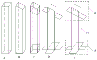
图3为支撑柱制作过程图;Fig. 3 is the manufacturing process diagram of support column;
图4为主梁与横梁安装结构示意图;Figure 4 is a schematic diagram of the installation structure of the main beam and the beam;
图5为角铁片结构示意图;Fig. 5 is the structural representation of angle iron sheet;
图6为斜拉杆结构示意图;Fig. 6 is a schematic diagram of the structure of the diagonal stay;
图7为支撑柱和斜拉杆连接示意图;Fig. 7 is a schematic diagram of the connection between the support column and the diagonal tie rod;
图8为太阳能板支架整体效果示意图;Figure 8 is a schematic diagram of the overall effect of the solar panel support;
图1~图8中,1为支撑柱、2为主梁、3为横梁、4为角铁片、7为斜拉杆、5为铆钉、6为地脚螺丝;In Figures 1 to 8, 1 is the support column, 2 is the main beam, 3 is the beam, 4 is the angle iron piece, 7 is the diagonal stay rod, 5 is the rivet, and 6 is the anchor screw;
111为前立板、112为后立板、113为右托板、114为左托板,131为前底板、132为右底板、133为后底板、134为左底板,71为前段面、72为后段面,73为前三角、74为后三角。111 is the front vertical plate, 112 is the rear vertical plate, 113 is the right supporting plate, 114 is the left supporting plate, 131 is the front base plate, 132 is the right base plate, 133 is the rear base plate, 134 is the left base plate, 71 is the front section surface, 72 73 is the front triangle, and 74 is the rear triangle.
具体实施方式Detailed ways
该发明包括支撑柱(1)、主梁(2)、横梁(3)、角铁片(4)、斜拉杆(7);支撑柱(1)与主梁(2),主梁(2)与横梁(3)、横梁(3)与角铁片(4)、支撑柱(1)与斜拉杆(7)之间全部采用铆钉(5)固定连接,支撑柱(1)与地面用地脚螺丝(6)固定,整个支架无需焊接。支撑柱(1)由方形金属管制作而成,包括支撑柱上部(11)、支撑柱中部(12)、支撑柱下部(13),支撑柱上部(11)、支撑柱中部(12)、支撑柱下部(13)三个部分至上而下成一个整体,即支撑柱上部(11)、支撑柱中部(12)、支撑柱下部(13)由一根整体方管加工而成;支撑柱上部(11)由方管制作而成,从方管四角切开分成四片,分别为前立板(111)、后立板(112)、右托板(113)和左托板(114),前立板(111)和后立板(112)对立形成一个平行叉,右托板(113)和左托板(114)弯折成一定角度,右托板(113)和左托板(114)在同一平面;支撑柱下部(13)由方管制作而成,从方管四角切开分成四片,分别为前底板(131)、右底板(132)、后底板(133)和左底板(134),将此四片底板弯折成与支撑柱(1)垂直的角度,此四片底板在同一个平面上;前底板(131)、右底板(132)、后底板(133)和左底板(134)均钻有孔,用于安装地脚螺丝(6),将支撑柱(1)固定在地面;右托板(113)和左托板(114)长度相同,左托板(114)高于右托板(113);左托板(114)和右托板(113)与主梁(2)平行,即左托板(114)和右托板(113)在同一斜面上,倾斜的角度与主梁(2)的倾斜角一致;前立板(111)、后立板(112)、右托板(113)和左托板(114)钻有孔,用于打铆钉,固定支撑柱(1)和主梁(2)。角铁片(4)为直角形,角铁片(4)的两面钻有孔,主梁(2)和横梁(3)通过角铁片(4)、铆钉(5)进行固定。斜拉杆(7)由一根整体金属方形管制作而成,斜拉杆(7)的上端切除对立的两片,剩余的两个对立面为前段面(71)和后段面(72),形成一个斜叉;斜拉杆(7)的下端切掉右边部分段面,前后面三角部分向前和向后弯折成直角,称为前三角(73)和后三角(74),前三角(73)和后三角(74)在同一个平面;前段面(71)、后段面(72),前三角(73)、后三角(74)钻有孔;斜拉杆(7)钳住支撑柱(1),即支撑柱(1)嵌入到斜拉杆(7)上端的斜叉中,并用铆钉(5)固定;斜拉杆(7)的下端的前三角(73)和后三角(74)用地脚螺丝(6)固定在地面。The invention comprises a support column (1), a main beam (2), a beam (3), an angle iron piece (4), and a diagonal stay rod (7); the support column (1) and the main beam (2), and the main beam (2) Rivets (5) are used to fix the connection between the beam (3), the beam (3) and the angle iron piece (4), the support column (1) and the diagonal tie rod (7), and the support column (1) and the ground use anchor screws (6) Fixed, the whole bracket does not need to be welded. The support column (1) is made of a square metal tube, including the support column upper part (11), the support column middle part (12), the support column lower part (13), the support column upper part (11), the support column middle part (12), the support column The three parts of the lower part of the column (13) form a whole from top to bottom, that is, the upper part of the support column (11), the middle part of the support column (12), and the lower part of the support column (13) are processed by an integral square tube; the upper part of the support column ( 11) It is made of a square tube, cut from the four corners of the square tube and divided into four pieces, namely the front vertical plate (111), the rear vertical plate (112), the right supporting plate (113) and the left supporting plate (114), the front The vertical plate (111) and the rear vertical plate (112) are opposed to form a parallel fork, the right supporting plate (113) and the left supporting plate (114) are bent into a certain angle, and the right supporting plate (113) and the left supporting plate (114) On the same plane; the lower part of the supporting column (13) is made of a square tube, which is cut into four pieces from the four corners of the square tube, which are respectively the front base plate (131), the right base plate (132), the rear base plate (133) and the left base plate ( 134), the four base plates are bent into an angle perpendicular to the support column (1), and the four base plates are on the same plane; the front base plate (131), the right base plate (132), the rear base plate (133) and the left Bottom plates (134) are drilled with holes, used to install anchor screws (6), and support columns (1) are fixed on the ground; right support plate (113) and left support plate (114) have the same length, and left support plate (114) ) is higher than the right supporting plate (113); the left supporting plate (114) and the right supporting plate (113) are parallel to the main beam (2), that is, the left supporting plate (114) and the right supporting plate (113) are on the same slope, The angle of inclination is consistent with the inclination angle of the main beam (2); the front vertical plate (111), the rear vertical plate (112), the right supporting plate (113) and the left supporting plate (114) are drilled with holes for rivets, Fix the supporting column (1) and the main beam (2). The angle iron sheet (4) is right-angled, and the two sides of the angle iron sheet (4) are drilled with holes, and the main beam (2) and the crossbeam (3) are fixed by the angle iron sheet (4) and the rivet (5). The diagonal tie rod (7) is made of an integral metal square tube. The upper end of the diagonal stay rod (7) cuts off two opposite pieces, and the remaining two opposite surfaces are the front section surface (71) and the rear section surface (72), forming a The oblique fork; the lower end of the oblique tie rod (7) cuts off the right section, and the front and rear triangles are bent forward and backward to form a right angle, called the front triangle (73) and the rear triangle (74), and the front triangle (73) It is on the same plane as the rear triangle (74); the front section surface (71), the rear section surface (72), the front triangle (73), and the rear triangle (74) are drilled with holes; the diagonal tie rod (7) clamps the support column (1 ), that is, the support column (1) is embedded in the diagonal fork at the upper end of the diagonal stay (7) and fixed with rivets (5); the front triangle (73) and rear triangle (74) at the lower end of the diagonal stay (7) use anchor screws (6) Fixed to the ground.
支撑柱(1)的制作过程如图3所示,其中,图A为一根未加工的方管,图B为上端根据主梁的倾斜角,切成斜角;图C为将上端和下端从方管的四角用手磨机切开,切入深度一致;图D为将上端分割得到的四片,左右两片分别向左向右弯折,成为左托板(114)、右托板(113),左托板(114)和右托板(113)在同一个面,倾斜角与主梁(2)一致,将下端的四片向外弯折成直角,构成前底板(131)、右底板(132)、后底板(133)和左底板(134);图E为制作完成的支撑柱。考虑钻孔方便,支撑柱下端的固定孔可以在切片前先钻,也可以制作完成时后钻。The manufacturing process of the support column (1) is shown in Figure 3, wherein Figure A is an unprocessed square tube, Figure B shows that the upper end is cut into a beveled angle according to the inclination angle of the main beam; Figure C shows that the upper end and the lower end Cut the four corners of the square pipe with a hand grinder, and the cutting depth is the same; Figure D shows the four pieces obtained by dividing the upper end, and the left and right pieces are respectively bent to the left and right to become the left supporting plate (114) and the right supporting plate ( 113), the left supporting plate (114) and the right supporting plate (113) are on the same surface, the inclination angle is consistent with the main beam (2), and the four pieces at the lower end are bent outwards to form a right angle, forming the front bottom plate (131), Right base plate (132), rear base plate (133) and left base plate (134); Fig. E is the supporting column that makes. Considering the convenience of drilling, the fixing hole at the lower end of the support column can be drilled before slicing, or it can be drilled after completion.
角铁片(4)如图5所示,其中图A为正视图,图B为侧视图,图C为俯视图,角铁片(4)采用热镀角铁加工制作,将长角铁切成长为2cm的角铁片,将角铁片(4)的两个面钻孔,用于打铆钉,将横梁(3)固定在主梁(2)上,如图4所示,其中图A为正视图,图B为俯视图。The angle iron piece (4) is shown in Figure 5, where picture A is a front view, picture B is a side view, and picture C is a top view, the angle iron piece (4) is made of hot-dip angle iron, and the long angle iron is cut into long For an angle iron sheet of 2cm, drill holes on both sides of the angle iron sheet (4) for rivets, and fix the beam (3) on the main beam (2), as shown in Figure 4, where Figure A is Front view, Figure B is a top view.
斜拉杆(7)如图6所示,其中图A为俯视图,图B为立体图,斜拉杆(7)由一根整体的方管制作而成,尺寸与支撑柱(1)一致,将方管的上端切成斜叉口,可以将支撑柱(1)嵌入到叉口内,前段面(71)和后段面(72)与支撑柱(1)打铆钉固定住;将方管的下端也切成斜叉口,将此斜叉口的斜三角向外弯折,得到前三角(73)和后三角(74),前三角(73)和后三角(74)钻孔,通过地脚螺丝固定在地板上。如图7所示为固定后的效果图,其中A为正视图,B为后视图。The diagonal tie rod (7) is shown in Figure 6, where Figure A is a top view and Figure B is a three-dimensional view. The diagonal stay rod (7) is made of an integral square tube with the same size as the support column (1). The upper end of the square tube is cut into an oblique fork, and the support column (1) can be embedded in the fork, and the front section surface (71) and the rear section surface (72) are fixed with the support column (1) by rivets; the lower end of the square tube is also cut Make a slanted fork, bend the slanted triangle of the slanted fork outward to obtain the front triangle (73) and rear triangle (74), drill holes in the front triangle (73) and rear triangle (74), and fix them with anchor screws on the floor. Figure 7 shows the fixed effect diagram, where A is the front view and B is the rear view.
图8为光伏板支架部分效果图,支撑柱、主梁、横梁的数量根据光伏板的数量而具体确定。本支架也可以用于风雨棚的建造或简易房的建造。Figure 8 is a partial effect diagram of the photovoltaic panel support, and the number of support columns, main beams, and beams is determined according to the number of photovoltaic panels. The support can also be used for the construction of the shelter or the construction of the simple house.
本实施例中,地脚螺丝(6)采用膨胀螺丝;铆钉(5)采用铝材料,铆钉(5)不受限制,也可以采用钢性自攻螺丝。In this embodiment, the anchor screws (6) are expansion screws; the rivets (5) are made of aluminum, and the rivets (5) are not limited, and steel self-tapping screws can also be used.
本实施例中,支承柱(1)、主梁(2)和斜拉杆(7)可以采用同一规格的方管,这样在安装过程中,支承柱(1)上端的平行叉向外拨开再将主梁(2)紧卡入,斜拉杆(7)上端的斜叉向外拨开再将支承柱(1)紧卡入,增加支架的牢固性。In this embodiment, the support column (1), the main beam (2) and the diagonal stay rod (7) can use square tubes of the same specification, so that during the installation process, the parallel fork at the upper end of the support column (1) is pulled outward and then Tightly snap in the main beam (2), move the oblique fork at the upper end of the diagonal tie rod (7) outward, and then snap in the support column (1) tightly to increase the firmness of the bracket.
Claims (4)
Priority Applications (1)
| Application Number | Priority Date | Filing Date | Title |
|---|---|---|---|
| CN202211098629.5A CN115664306A (en) | 2022-09-09 | 2022-09-09 | A method of manufacturing and installing a solar panel fixing bracket |
Applications Claiming Priority (1)
| Application Number | Priority Date | Filing Date | Title |
|---|---|---|---|
| CN202211098629.5A CN115664306A (en) | 2022-09-09 | 2022-09-09 | A method of manufacturing and installing a solar panel fixing bracket |
Publications (1)
| Publication Number | Publication Date |
|---|---|
| CN115664306A true CN115664306A (en) | 2023-01-31 |
Family
ID=84983372
Family Applications (1)
| Application Number | Title | Priority Date | Filing Date |
|---|---|---|---|
| CN202211098629.5A Pending CN115664306A (en) | 2022-09-09 | 2022-09-09 | A method of manufacturing and installing a solar panel fixing bracket |
Country Status (1)
| Country | Link |
|---|---|
| CN (1) | CN115664306A (en) |
Citations (5)
| Publication number | Priority date | Publication date | Assignee | Title |
|---|---|---|---|---|
| CN201741703U (en) * | 2010-05-07 | 2011-02-09 | 江苏东升光伏发电设备有限公司 | Solar cell component bracket |
| KR101960276B1 (en) * | 2018-11-12 | 2019-03-20 | 최원보 | Floor Support Apparatus For Seismic Isolation Equipment Double Deck |
| CN109811886A (en) * | 2019-04-03 | 2019-05-28 | 曹友国 | A kind of prefabricated buildings structure |
| KR20190128356A (en) * | 2018-05-08 | 2019-11-18 | 드림에너지주식회사 | Prefabricated Solar Structure |
| CN215871268U (en) * | 2021-05-06 | 2022-02-18 | 甘肃科耀电力有限公司 | Single-pile photovoltaic support rapid to install |
-
2022
- 2022-09-09 CN CN202211098629.5A patent/CN115664306A/en active Pending
Patent Citations (5)
| Publication number | Priority date | Publication date | Assignee | Title |
|---|---|---|---|---|
| CN201741703U (en) * | 2010-05-07 | 2011-02-09 | 江苏东升光伏发电设备有限公司 | Solar cell component bracket |
| KR20190128356A (en) * | 2018-05-08 | 2019-11-18 | 드림에너지주식회사 | Prefabricated Solar Structure |
| KR101960276B1 (en) * | 2018-11-12 | 2019-03-20 | 최원보 | Floor Support Apparatus For Seismic Isolation Equipment Double Deck |
| CN109811886A (en) * | 2019-04-03 | 2019-05-28 | 曹友国 | A kind of prefabricated buildings structure |
| CN215871268U (en) * | 2021-05-06 | 2022-02-18 | 甘肃科耀电力有限公司 | Single-pile photovoltaic support rapid to install |
Similar Documents
| Publication | Publication Date | Title |
|---|---|---|
| CN208072857U (en) | A kind of building wall body insulating board dedicated hanging part structure | |
| CN111648620A (en) | An installation structure of a cantilever and a support beam | |
| CN207228743U (en) | A kind of antidetonation right-angled intersection is tiltedly slotted corrugated steel shear wall | |
| CN222478133U (en) | Suspended floor template | |
| CN201493783U (en) | A Universal Combined Horizontal Assembly Fixture Frame | |
| CN116816027B (en) | Modularized building component structure | |
| CN219386807U (en) | Soft stone reverse hanging structure | |
| CN107905476B (en) | Construction method of grille decorative surface suitable for high-rise aerated block walls | |
| CN214575651U (en) | An adjustable steel truss floor deck construction support device | |
| CN217913703U (en) | Pre-buried steel sheet welded fastening device that can lower temperature | |
| CN202266025U (en) | Support structure for on-site concrete beam template | |
| CN220203000U (en) | Reinforced concrete beam side shear-resistant embedded part | |
| CN212115209U (en) | Photovoltaic base, photovoltaic base mounting structure and photovoltaic support | |
| CN205777538U (en) | Setting assembling type reinforcing bar protection canopy structure | |
| CN222880550U (en) | Novel supporting and hanging frame connecting floor structure | |
| CN209941512U (en) | A kind of cable-stayed bridge inclined tower lower beam supporting shear member | |
| CN222649367U (en) | Be used for receiving and mould outer flitch installation auxiliary stay device | |
| CN223661303U (en) | A leveling device for installing anti-static flooring in a power distribution room | |
| CN211118002U (en) | Supporting and fixing part for electromechanical pipeline on steel beam | |
| CN223124818U (en) | A beam-column diagonal bracing member for photovoltaic support and photovoltaic system | |
| CN222559400U (en) | A hanger device for steel structure | |
| CN222333244U (en) | Multi-purpose scaffolding pole fixing device | |
| CN221010025U (en) | A positioning tool for fixing auxiliary bracket purlins | |
| CN220203003U (en) | A constant-height connection structure between concrete columns and steel beams | |
| CN216807810U (en) | Assembled can have enough to meet need many sizes composite beam support steel corbel |
Legal Events
| Date | Code | Title | Description |
|---|---|---|---|
| PB01 | Publication | ||
| PB01 | Publication | ||
| SE01 | Entry into force of request for substantive examination | ||
| SE01 | Entry into force of request for substantive examination |