CN115648983A - A boost charging device and method for electric vehicles - Google Patents
A boost charging device and method for electric vehicles Download PDFInfo
- Publication number
- CN115648983A CN115648983A CN202211320896.2A CN202211320896A CN115648983A CN 115648983 A CN115648983 A CN 115648983A CN 202211320896 A CN202211320896 A CN 202211320896A CN 115648983 A CN115648983 A CN 115648983A
- Authority
- CN
- China
- Prior art keywords
- voltage
- boost
- voltage connector
- inductor
- relay
- Prior art date
- Legal status (The legal status is an assumption and is not a legal conclusion. Google has not performed a legal analysis and makes no representation as to the accuracy of the status listed.)
- Pending
Links
Images


Classifications
-
- Y—GENERAL TAGGING OF NEW TECHNOLOGICAL DEVELOPMENTS; GENERAL TAGGING OF CROSS-SECTIONAL TECHNOLOGIES SPANNING OVER SEVERAL SECTIONS OF THE IPC; TECHNICAL SUBJECTS COVERED BY FORMER USPC CROSS-REFERENCE ART COLLECTIONS [XRACs] AND DIGESTS
- Y02—TECHNOLOGIES OR APPLICATIONS FOR MITIGATION OR ADAPTATION AGAINST CLIMATE CHANGE
- Y02T—CLIMATE CHANGE MITIGATION TECHNOLOGIES RELATED TO TRANSPORTATION
- Y02T10/00—Road transport of goods or passengers
- Y02T10/60—Other road transportation technologies with climate change mitigation effect
- Y02T10/70—Energy storage systems for electromobility, e.g. batteries
-
- Y—GENERAL TAGGING OF NEW TECHNOLOGICAL DEVELOPMENTS; GENERAL TAGGING OF CROSS-SECTIONAL TECHNOLOGIES SPANNING OVER SEVERAL SECTIONS OF THE IPC; TECHNICAL SUBJECTS COVERED BY FORMER USPC CROSS-REFERENCE ART COLLECTIONS [XRACs] AND DIGESTS
- Y02—TECHNOLOGIES OR APPLICATIONS FOR MITIGATION OR ADAPTATION AGAINST CLIMATE CHANGE
- Y02T—CLIMATE CHANGE MITIGATION TECHNOLOGIES RELATED TO TRANSPORTATION
- Y02T10/00—Road transport of goods or passengers
- Y02T10/60—Other road transportation technologies with climate change mitigation effect
- Y02T10/7072—Electromobility specific charging systems or methods for batteries, ultracapacitors, supercapacitors or double-layer capacitors
-
- Y—GENERAL TAGGING OF NEW TECHNOLOGICAL DEVELOPMENTS; GENERAL TAGGING OF CROSS-SECTIONAL TECHNOLOGIES SPANNING OVER SEVERAL SECTIONS OF THE IPC; TECHNICAL SUBJECTS COVERED BY FORMER USPC CROSS-REFERENCE ART COLLECTIONS [XRACs] AND DIGESTS
- Y02—TECHNOLOGIES OR APPLICATIONS FOR MITIGATION OR ADAPTATION AGAINST CLIMATE CHANGE
- Y02T—CLIMATE CHANGE MITIGATION TECHNOLOGIES RELATED TO TRANSPORTATION
- Y02T90/00—Enabling technologies or technologies with a potential or indirect contribution to GHG emissions mitigation
- Y02T90/10—Technologies relating to charging of electric vehicles
- Y02T90/14—Plug-in electric vehicles
Landscapes
- Electric Propulsion And Braking For Vehicles (AREA)
- Charge And Discharge Circuits For Batteries Or The Like (AREA)
Abstract
本发明涉及一种用于电动汽车的升压充电装置及方法,所述升压充电装置包括模块壳体,所述模块壳体的侧部设有输入端高压接插件和输出端高压接插件以及控制信号线,水道接口等;所述模块壳体的内部设有升压电感器,高压继电器、高压滤波组件、薄膜电容、控制电路,和固定支撑件组成。所述输入端高压接插件与升压电感器相连接;所述模块壳体的侧部设有高压连接器,所述高压连接器与升压电感器相连接。本发明能够适用不同输出电压的充电桩,从而提高汽车充电模式的兼容性,实现在不同输出电压的充电桩下的快速充电功能。
The invention relates to a boost charging device and method for an electric vehicle. The boost charging device includes a module housing, and the side of the module housing is provided with an input end high voltage connector and an output end high voltage connector and Control signal line, water channel interface, etc.; the inside of the module housing is composed of a boost inductor, a high voltage relay, a high voltage filter component, a film capacitor, a control circuit, and a fixed support. The high-voltage connector at the input end is connected to the boost inductor; a high-voltage connector is provided on the side of the module housing, and the high-voltage connector is connected to the boost inductor. The present invention can be applied to charging piles with different output voltages, thereby improving the compatibility of the charging modes of automobiles, and realizing the fast charging function under charging piles with different output voltages.
Description
技术领域technical field
本发明属于升压充电技术领域,特别涉及一种用于电动汽车的升压充电装置及方法。The invention belongs to the technical field of boost charging, in particular to a boost charging device and method for electric vehicles.
背景技术Background technique
较目前来看集成的PDU充电装置,布局功能太多,内部结构交错复杂,散热共用一个冷却水路,整体散热性能较差,高压和低压之间排布密集,干扰较大,并且拆卸维修麻烦。Compared with the current integrated PDU charging device, there are too many layout functions, the internal structure is intertwined and complicated, the heat dissipation shares a cooling water circuit, the overall heat dissipation performance is poor, the high voltage and low voltage are densely arranged, the interference is large, and disassembly and maintenance are troublesome.
市面大多数充电桩输出的电压相对较低,一般集成PDU装置无法发挥高电压大功率充电的优势,达到真正意义上的快速充电功能。如果汽车企业自己建设充电桩,第一是没办法大范围全国覆盖充电站点,二是不同的车企充电模式和接口数据不同,兼容性较差。充电桩的输出电压过低,会导致汽车在充电时所需要的时间过长,影响充电的效率,所以一直以来电动汽车快速充电,对于众多车企也是迫在眉睫需要解决的问题,一是需要解决充电速度慢,二是解决充电的安全问题。The output voltage of most charging piles on the market is relatively low, and the general integrated PDU device cannot take advantage of high-voltage and high-power charging to achieve the real fast charging function. If the car companies build their own charging piles, firstly, there is no way to cover a large range of charging stations nationwide, and secondly, different car companies have different charging modes and interface data, resulting in poor compatibility. If the output voltage of the charging pile is too low, it will take too long for the car to charge and affect the charging efficiency. Therefore, the fast charging of electric vehicles has always been an urgent problem for many car companies. One is to solve the problem of charging. The speed is slow, and the second is to solve the safety problem of charging.
为了解决上述问题,需要设计一种用于电动汽车的升压充电装置及方法。In order to solve the above problems, it is necessary to design a boost charging device and method for electric vehicles.
发明内容Contents of the invention
针对上述问题,本发明提供一种用于电动汽车的升压充电装置,所述升压充电装置包括模块壳体,In view of the above problems, the present invention provides a boost charging device for electric vehicles, the boost charging device includes a module housing,
所述模块壳体的侧部设有输入端高压接插件和输出端高压接插件;所述模块壳体的内部设有升压电感器,所述输入端高压接插件与升压电感器相连接;所述模块壳体的侧部设有高压连接器,所述高压连接器与升压电感器相连接。The side of the module housing is provided with an input-end high-voltage connector and an output-end high-voltage connector; the inside of the module housing is provided with a boost inductor, and the input-end high-voltage connector is connected to the boost inductor ; The side of the module housing is provided with a high-voltage connector, and the high-voltage connector is connected with the boost inductor.
优选的,所述输入端高压接插件与高压连接器之间依次连接有继电器、高压滤波组件、薄膜电容和正极继电器;Preferably, a relay, a high-voltage filter assembly, a film capacitor and a positive relay are sequentially connected between the high-voltage connector at the input end and the high-voltage connector;
所述薄膜电容与高压连接器之间还连接有负极继电器;A negative relay is also connected between the film capacitor and the high voltage connector;
所述模块壳体的侧部还设有低压控制信号接插件。The side of the module housing is also provided with a low-voltage control signal connector.
优选的,所述模块壳体内部设置有水道,所述升压电感器设置在水道上方;Preferably, a waterway is arranged inside the module housing, and the boost inductor is arranged above the waterway;
所述模块壳体的侧部设有与水道相连通的进出水嘴。The side part of the module housing is provided with a water inlet and outlet mouth connected with the water channel.
优选的,所述升压电感器的上方设有支撑屏蔽板,所述支撑屏蔽板的上方设有控制电路板,继电器、负极继电器和正极继电器均控制电路板相连接。Preferably, a support shielding plate is provided above the boost inductor, a control circuit board is provided above the support shielding plate, and the relay, the negative relay and the positive relay are all connected to the control circuit board.
优选的,所述模块壳体内部设有高压继电器,所述高压继电器与输入端高压接插件相连接,所述高压继电器与高压滤波组件相连接。Preferably, a high-voltage relay is provided inside the module housing, the high-voltage relay is connected to the high-voltage connector at the input end, and the high-voltage relay is connected to the high-voltage filter assembly.
优选的,所述高压滤波组件包括固定座,所述固定座上设有滤波PCB板,所述滤波PCB板上设有第一滤波电容和第二滤波电容。Preferably, the high-voltage filter assembly includes a fixing base, and a filtering PCB board is arranged on the fixing base, and a first filtering capacitor and a second filtering capacitor are arranged on the filtering PCB board.
优选的,所述固定座的侧部具有滤波磁环和磁环盖板,所述固定座通过注塑一体嵌入铜排,所述滤波PCB板通过螺栓固定在固定座,使铜排的引出针脚焊接在滤波PCB板孔中。Preferably, the side of the fixing seat has a filter magnetic ring and a magnetic ring cover plate, and the fixing seat is integrated into the copper bar through injection molding, and the filter PCB board is fixed on the fixing seat by bolts, so that the lead-out pins of the copper bar are welded In the filter PCB board hole.
优选的,所述升压电感器包括电感外壳,所述电感外壳的内部设有电感铁芯,所述电感铁芯的外部缠绕有线圈;所述电感外壳内部还设有热敏电阻信号线;Preferably, the boost inductor includes an inductance shell, an inductor core is provided inside the inductor shell, and a coil is wound outside the inductor core; a thermistor signal line is also provided inside the inductor shell;
所述电感铁芯的两侧均设有固定件,固定件与电感外壳相连接。Both sides of the inductance iron core are provided with fixing parts, and the fixing parts are connected with the inductance shell.
优选的,所述模块壳体上设有壳体大盖板,所述壳体大盖板与模块壳体上端面匹配。Preferably, a large housing cover is provided on the module housing, and the large housing cover matches the upper end surface of the module housing.
优选的,所述升压电感器底部涂有导热硅脂和或固定连接有导热垫片。Preferably, the bottom of the boost inductor is coated with thermally conductive silicone grease and or is fixedly connected with a thermally conductive gasket.
优选的,所述模块壳体内底部设有散热板,所述电感外壳底部与散热板固定连接。Preferably, a heat dissipation plate is provided at the inner bottom of the module housing, and the bottom of the inductor housing is fixedly connected with the heat dissipation plate.
本发明还提出一种用于电动汽车的升压充电方法,所述升压充电方法包括:The present invention also proposes a boost charging method for an electric vehicle, the boost charging method comprising:
充电桩的充电枪通过整车高压充电插口,输入电流,正极电流从输入端高压接插件流入,然后流向升压电感器,然后流向高压连接器;The charging gun of the charging pile passes through the high-voltage charging socket of the vehicle, input current, and the positive current flows from the high-voltage connector at the input end, then flows to the boost inductor, and then flows to the high-voltage connector;
负极电流从输入端高压接插件流入,然后流向高压连接器,最终流向汽车的电机控制器的整体电路。The negative current flows from the high-voltage connector at the input end, then flows to the high-voltage connector, and finally flows to the overall circuit of the motor controller of the car.
优选的,在执行所述升压充电方法之前,包括:Preferably, before performing the boost charging method, including:
判断外部输入直流电压是否大于汽车电池电压,如果大于汽车电池电压,则进行直充模式;Judging whether the external input DC voltage is greater than the car battery voltage, if it is greater than the car battery voltage, the direct charging mode is performed;
如果小于或者等于汽车电池电压,则执行升压充电方法;If it is less than or equal to the car battery voltage, the boost charging method is performed;
其中,所述直充模式包括:电流从输入端高压接插件流入,然后从输出端高压接插件流出,最终流向汽车的电机控制器的整体电路。Wherein, the direct charging mode includes: current flows in from the high-voltage connector at the input end, then flows out from the high-voltage connector at the output end, and finally flows to the overall circuit of the motor controller of the vehicle.
优选的,所述升压充电方法还包括:Preferably, the boost charging method also includes:
正极电流从输入端高压接插件流入后,通过高压滤波组件进行滤波除杂,然后流入升压电感器;After the positive current flows in from the high-voltage connector at the input end, it is filtered and removed by the high-voltage filter component, and then flows into the boost inductor;
负极电流从输入端高压接插件流入后,通过高压滤波组件除杂,再流向高压连接器。After the negative current flows in from the high-voltage connector at the input end, it passes through the high-voltage filter component to remove impurities, and then flows to the high-voltage connector.
本发明具有以下有益效果:The present invention has the following beneficial effects:
(1)本发明通过在充电装置的内部设置升压电感器,能够在充电桩的输出电压低于电池的额定充电电压时实现升压充电的功能,相较于现有的充电装置而言,本发明能够适用不同输出电压的充电桩,从而提高汽车充电模式的兼容性,实现在不同输出电压的充电桩下的快速充电功能;(1) The present invention can realize the function of boost charging when the output voltage of the charging pile is lower than the rated charging voltage of the battery by arranging a boost inductor inside the charging device. Compared with the existing charging device, The present invention can be applied to charging piles with different output voltages, thereby improving the compatibility of the charging modes of automobiles, and realizing the fast charging function under charging piles with different output voltages;
(2)本发明中,在输入端高压接插件和高压连接器之间还设有高压滤波组件,能够对充电装置内部的电流进行除杂滤波处理,提高装置的充电效果,并且,高压滤波组件通过一体化、模块化设计将多个滤波器件集合在一起,能保证在有限的空间内最大化提高模块的滤波能力,整体布局紧密且整洁,空间利用合理。(2) In the present invention, a high-voltage filter assembly is also provided between the high-voltage connector at the input end and the high-voltage connector, which can remove impurities and filter the current inside the charging device to improve the charging effect of the device, and the high-voltage filter assembly The integrated and modular design integrates multiple filter components together, which can ensure the maximum improvement of the filter capability of the module in a limited space. The overall layout is compact and tidy, and the space utilization is reasonable.
本发明的其它特征和优点将在随后的说明书中阐述,并且,部分地从说明书中变得显而易见,或者通过实施本发明而了解。本发明的目的和其他优点可通过在说明书、权利要求书以及附图中所指出的结构来实现和获得。Additional features and advantages of the invention will be set forth in the description which follows, and in part will be apparent from the description, or may be learned by practice of the invention. The objectives and other advantages of the invention may be realized and attained by the structure pointed out in the written description, claims hereof as well as the appended drawings.
附图说明Description of drawings
为了更清楚地说明本发明实施例或现有技术中的技术方案,下面将对实施例或现有技术描述中所需要使用的附图作一简单地介绍,显而易见地,下面描述中的附图是本发明的一些实施例,对于本领域普通技术人员来讲,在不付出创造性劳动的前提下,还可以根据这些附图获得其他的附图。In order to more clearly illustrate the technical solutions in the embodiments of the present invention or the prior art, the following will briefly introduce the drawings that need to be used in the description of the embodiments or the prior art. Obviously, the accompanying drawings in the following description These are some embodiments of the present invention. Those skilled in the art can also obtain other drawings based on these drawings without creative work.
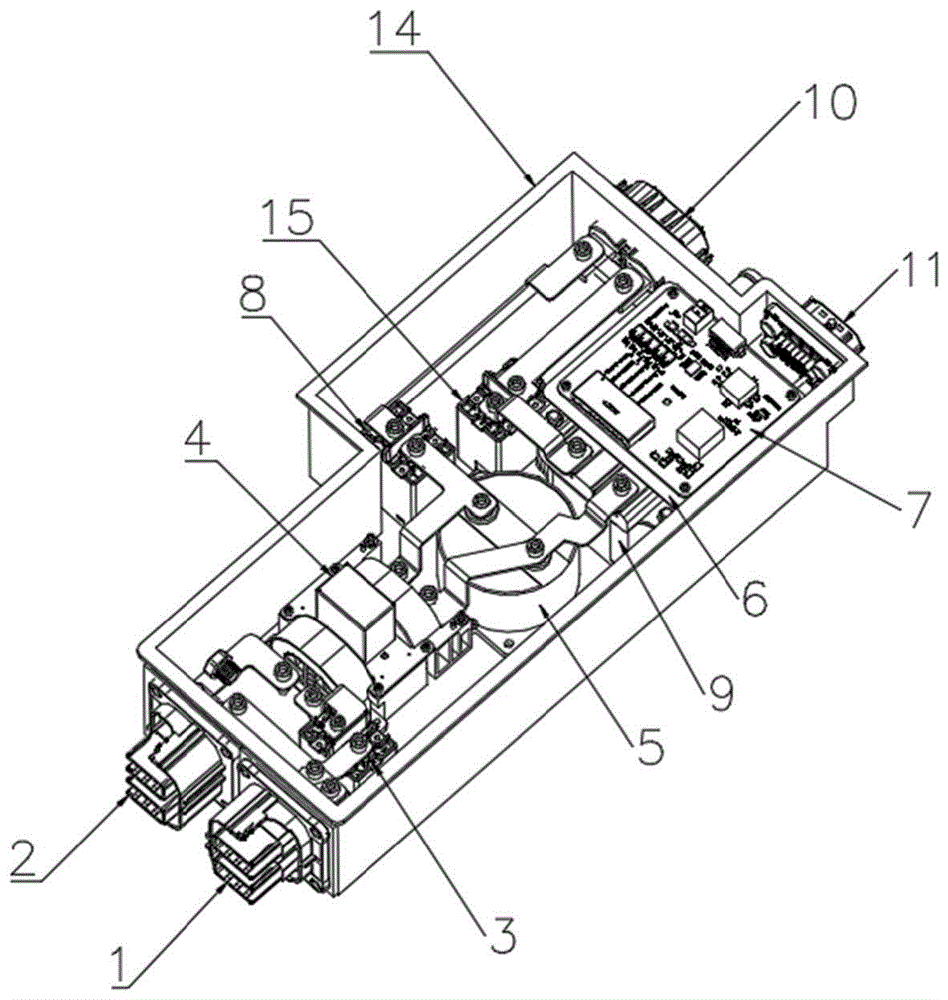
图1示出本发明实施例中升压充电装置内部结构示意图;Figure 1 shows a schematic diagram of the internal structure of a boost charging device in an embodiment of the present invention;
图2示出本发明实施例中升压充电装置内部结构爆炸示意图;Fig. 2 shows an exploded schematic view of the internal structure of the boost charging device in the embodiment of the present invention;
图3示出本发明实施例中高压滤波组件示意图;Fig. 3 shows a schematic diagram of a high-voltage filter assembly in an embodiment of the present invention;
图4示出本发明实施例中升压电感模块结构示意图;FIG. 4 shows a schematic structural diagram of a boost inductor module in an embodiment of the present invention;
图5示出本发明实施例中升压充电方法的流程图。Fig. 5 shows a flow chart of a boost charging method in an embodiment of the present invention.
图中:1、输入端高压接插件;2、输出端高压接插件;3、继电器;4、高压滤波组件;401、第一滤波电容;402、第二滤波电容;403、磁环盖板;404、滤波PCB板;405、固定座;406、滤波磁环;407、铜排;5、薄膜电容;6、支撑屏蔽板;7、控制电路板;8、负极继电器;9、升压电感器;901、热敏电阻信号线;902、线圈;903、电感铁芯;904、固定件;905、电感外壳;10、高压连接器;11、低压控制信号接插件;12、进出水嘴;13、壳体大盖板;14、模块壳体;15、正极继电器;16、高压继电器。In the figure: 1. Input high-voltage connector; 2. Output high-voltage connector; 3. Relay; 4. High-voltage filter component; 401, first filter capacitor; 402, second filter capacitor; 403, magnetic ring cover; 404, filter PCB board; 405, fixed seat; 406, filter magnetic ring; 407, copper bar; 5, film capacitor; 6, support shielding plate; 7, control circuit board; 8, negative relay; 9, boost inductor ;901, thermistor signal line; 902, coil; 903, inductance iron core; 904, fixing piece; 905, inductance shell; 10, high-voltage connector; 11, low-voltage control signal connector; 1. The large cover plate of the shell; 14. The module shell; 15. The positive relay; 16. The high voltage relay.
具体实施方式Detailed ways
为使本发明实施例的目的、技术方案和优点更加清楚,下面将结合本发明实施例中的附图,对本发明实施例中的技术方案进行清楚、完整地说明,显然,所描述的实施例是本发明一部分实施例,而不是全部的实施例。基于本发明中的实施例,本领域普通技术人员在没有做出创造性劳动前提下所获得的所有其他实施例,都属于本发明保护的范围。In order to make the purpose, technical solutions and advantages of the embodiments of the present invention more clear, the technical solutions in the embodiments of the present invention will be clearly and completely described below in conjunction with the accompanying drawings in the embodiments of the present invention. Obviously, the described embodiments It is a part of embodiments of the present invention, but not all embodiments. Based on the embodiments of the present invention, all other embodiments obtained by persons of ordinary skill in the art without making creative efforts belong to the protection scope of the present invention.
本发明提供一种用于电动汽车的升压充电装置,如图1所示,所述装置包括模块壳体14,所述模块壳体14的侧部设有输入端高压接插件1和输出端高压接插件2;所述模块壳体14的内部设有升压电感器9,所述输入端高压接插件1与升压电感器9相连接;所述模块壳体14的侧部设有高压连接器10,所述高压连接器10与升压电感器9相连接。所述输入端高压接插件1与高压连接器10之间依次连接有继电器3、高压滤波组件4、薄膜电容5和正极继电器15,当检测电压大于800V时,继电器3断开,当电压小于800V时继电器3导通升压回路;所述薄膜电容5与高压连接器10之间还连接有负极继电器8,设置正极继电器15和负极继电器8能够起到安全防护的作用,避免电路过压冲坏设备。所述模块壳体14的侧部还设有低压控制信号接插件11。The present invention provides a boost charging device for electric vehicles, as shown in Figure 1, the device includes a
如图2所示,所述模块壳体14内部设置有水道,所述升压电感器9设置在水道上方,避免升压电感器9在工作时周围温度较高;所述模块壳体14的侧部设有与水道相连通的进出水嘴12,高压连接器10、低压控制信号接插件11和进出水嘴12通过螺栓固定在模块壳体14侧壁,进出水嘴12与散热水泵连接。所述升压电感器9的上方设有支撑屏蔽板6,减轻了整体重量,阻隔下方升压电感高电压对控制板的干扰,也保证了绝缘强度,所述支撑屏蔽板6的上方设有控制电路板7,所述控制电路板7与低压控制信号接插件11相连接,继电器3、负极继电器8和正极继电器15均控制电路板7相连接,控制电路板7能够控制继电器3、负极继电器8和正极继电器15的通断。控制电路板7还与升压电感器9的温度线相连,能够监测升压电感器9的温度大小。控制电路板7还与输入端高压接插件1、输出端高压接插件2和高压连接器10的互锁线束相连,能够监测高压通断。控制电路板7的外部与低压控制信号接插件11相连接,能够实现信号传输功能。所述模块壳体14内部设有高压继电器16,高压继电器16通过螺栓锁附在模块壳体14内底部,所述高压继电器16与输入端高压接插件1相连接,所述高压继电器16与高压滤波组件4相连接。所述模块壳体14上设有壳体大盖板13,所述壳体大盖板13与模块壳体14上端面匹配。As shown in Figure 2, the inside of the
如图3所示,所述高压滤波组件4包括固定座405,所述固定座405上设有滤波PCB板404,所述滤波PCB板404上设有第一滤波电容401和第二滤波电容402。所述固定座405的侧部具有滤波磁环406和磁环盖板403,所述固定座405通过注塑一体嵌入铜排407,所述滤波PCB板404通过螺栓固定在固定座405,使铜排407的表面引出针脚焊接在滤波PCB板孔404中。上述设计通过一体化、模块化设计将众多滤波器件集合到一起,能保证在有限的空间内,最大化提高模块的滤波能力。As shown in Figure 3, the high-
如图4所示,所述升压电感器9包括电感外壳905,电感外壳905采用高效散热环保材质,本实施例中,电感外壳905采用的是铝壳,铝壳作为固定腔体。所述电感外壳905的内部设有电感铁芯903,所述电感铁芯903的外部缠绕有线圈902,并使用灌封工艺将电感铁芯903封装在电感外壳905中,有效保障大功率散热需求;所述电感外壳905内部还设有热敏电阻信号线901,本实施例中,热敏电阻信号线901采用的是NTC热敏电阻信号线,能够在工作状态下监测电感温度变化,从而有效的控制设备工作功率大小,保证器件不会在高温下损耗或超负荷工作。使得设备稳定且长久的安全运行工况。所述电感铁芯903的两侧均设有固定件904,固定件904与电感外壳905相连接,所述固定件904和电感外壳905用于固定电感铁芯903。所述升压电感器9底部涂有导热硅脂和或固定连接有导热垫片,采用导热硅脂和导热垫片能够减少散热介质,通过水道进行散热时使热量更快的被冷却水带走,从而达到最大化冷却效率。所述模块壳体14内底部设有散热板,所述电感外壳905底部与散热板固定连接。As shown in FIG. 4 , the boost inductor 9 includes an
本发明还提供一种用于电动汽车的升压充电方法,如图5所示,所述升压充电方法包括:充电桩的充电枪通过整车高压充电插口,输入电流,正极电流从输入端高压接插件1流入,然后流向升压电感器9,然后流向高压连接器10;负极电流从输入端高压接插件1流入,然后流向高压连接器10,最终流向汽车的电机控制器的整体电路。The present invention also provides a boost charging method for an electric vehicle. As shown in FIG. 5, the boost charging method includes: the charging gun of the charging pile passes through the high-voltage charging socket of the whole vehicle, and the input current and the positive current from the input terminal The high-
在执行所述升压充电方法之前,包括:判断外部输入直流电压是否大于汽车电池电压,如果大于汽车电池电压,则进行直充模式;如果小于或者等于汽车电池电压,则执行升压充电方法;其中,所述直充模式包括:电流从输入端高压接插件1流入,然后从输出端高压接插件2流出,最终流向汽车的电机控制器的整体电路。Before performing the boost charging method, it includes: judging whether the external input direct current voltage is greater than the vehicle battery voltage, if it is greater than the vehicle battery voltage, then performing the direct charging mode; if it is less than or equal to the vehicle battery voltage, then performing the boost charging method; Wherein, the direct charging mode includes: current flows in from the high-
所述升压充电方法还包括:正极电流从输入端高压接插件1流入后,通过高压滤波组件4进行滤波除杂,然后流入升压电感器9;负极电流从输入端高压接插件1流入后,通过高压滤波组件4除杂,再流向高压连接器10。The boost charging method also includes: after the positive current flows in from the high-
本领域的普通技术人员应当理解:尽管参考前述实施例对本发明进行的详细说明,其依然可以对前述各实施例所记载的技术方案进行修改,或者对其中部分技术特征进行等同替换;而这些修改或者替换,并不使相应技术方案的本质脱离本发明各实施例技术方案的精神和范围。Those of ordinary skill in the art should understand that: although the present invention has been described in detail with reference to the foregoing embodiments, it is still possible to modify the technical solutions described in the foregoing embodiments, or perform equivalent replacements for some of the technical features; and these modifications Or replacement, does not make the essence of the corresponding technical solutions deviate from the spirit and scope of the technical solutions of the various embodiments of the present invention.
Claims (14)
Priority Applications (1)
| Application Number | Priority Date | Filing Date | Title |
|---|---|---|---|
| CN202211320896.2A CN115648983A (en) | 2022-10-26 | 2022-10-26 | A boost charging device and method for electric vehicles |
Applications Claiming Priority (1)
| Application Number | Priority Date | Filing Date | Title |
|---|---|---|---|
| CN202211320896.2A CN115648983A (en) | 2022-10-26 | 2022-10-26 | A boost charging device and method for electric vehicles |
Publications (1)
| Publication Number | Publication Date |
|---|---|
| CN115648983A true CN115648983A (en) | 2023-01-31 |
Family
ID=84990738
Family Applications (1)
| Application Number | Title | Priority Date | Filing Date |
|---|---|---|---|
| CN202211320896.2A Pending CN115648983A (en) | 2022-10-26 | 2022-10-26 | A boost charging device and method for electric vehicles |
Country Status (1)
| Country | Link |
|---|---|
| CN (1) | CN115648983A (en) |
Cited By (1)
| Publication number | Priority date | Publication date | Assignee | Title |
|---|---|---|---|---|
| CN119765574A (en) * | 2024-12-30 | 2025-04-04 | 武汉嘉晨电子技术股份有限公司 | Vehicle-mounted booster and vehicle |
Citations (7)
| Publication number | Priority date | Publication date | Assignee | Title |
|---|---|---|---|---|
| CN210839338U (en) * | 2019-11-26 | 2020-06-23 | 合肥巨一动力系统有限公司 | A high-voltage module structure integrating EMC components |
| DE102019219456A1 (en) * | 2019-12-12 | 2021-06-17 | Vitesco Technologies GmbH | Power charging circuit, vehicle electrical system and method for operating a power charging circuit |
| WO2022007706A1 (en) * | 2020-07-09 | 2022-01-13 | 比亚迪股份有限公司 | Winding assembly, on-board charger, and vehicle |
| CN216162132U (en) * | 2021-09-16 | 2022-04-01 | 一巨自动化装备(上海)有限公司 | High-voltage distribution box and vehicle |
| CN216390934U (en) * | 2021-11-15 | 2022-04-26 | 一巨自动化装备(上海)有限公司 | DC end multistage filtering structure, motor controller and vehicle |
| CN115107542A (en) * | 2022-06-27 | 2022-09-27 | 浙江伊控动力系统有限公司 | All-in-one integrated booster device and integration method thereof |
| WO2022217619A1 (en) * | 2021-04-17 | 2022-10-20 | 深圳欣锐科技股份有限公司 | Voltage conversion circuit, voltage conversion apparatus, voltage conversion chip and charging device |
-
2022
- 2022-10-26 CN CN202211320896.2A patent/CN115648983A/en active Pending
Patent Citations (7)
| Publication number | Priority date | Publication date | Assignee | Title |
|---|---|---|---|---|
| CN210839338U (en) * | 2019-11-26 | 2020-06-23 | 合肥巨一动力系统有限公司 | A high-voltage module structure integrating EMC components |
| DE102019219456A1 (en) * | 2019-12-12 | 2021-06-17 | Vitesco Technologies GmbH | Power charging circuit, vehicle electrical system and method for operating a power charging circuit |
| WO2022007706A1 (en) * | 2020-07-09 | 2022-01-13 | 比亚迪股份有限公司 | Winding assembly, on-board charger, and vehicle |
| WO2022217619A1 (en) * | 2021-04-17 | 2022-10-20 | 深圳欣锐科技股份有限公司 | Voltage conversion circuit, voltage conversion apparatus, voltage conversion chip and charging device |
| CN216162132U (en) * | 2021-09-16 | 2022-04-01 | 一巨自动化装备(上海)有限公司 | High-voltage distribution box and vehicle |
| CN216390934U (en) * | 2021-11-15 | 2022-04-26 | 一巨自动化装备(上海)有限公司 | DC end multistage filtering structure, motor controller and vehicle |
| CN115107542A (en) * | 2022-06-27 | 2022-09-27 | 浙江伊控动力系统有限公司 | All-in-one integrated booster device and integration method thereof |
Non-Patent Citations (3)
| Title |
|---|
| 刘朝英主编;袁湘鄂副主编: "列控车载设备 CTCS2-200C型", 30 September 2011, 北京:中国铁道出版社 , pages: 151 - 155 * |
| 周洁敏,赵修科,陶思钰编著: "开关电源磁性元件理论及设计", 31 January 2014, 北京航空航天大学出版社, pages: 249 - 253 * |
| 颜荣江,詹树仁编译: "MAXIM热门集成电路使用手册 第4册", 31 October 1999, 人民邮电出版社, pages: 159 - 178 * |
Cited By (1)
| Publication number | Priority date | Publication date | Assignee | Title |
|---|---|---|---|---|
| CN119765574A (en) * | 2024-12-30 | 2025-04-04 | 武汉嘉晨电子技术股份有限公司 | Vehicle-mounted booster and vehicle |
Similar Documents
| Publication | Publication Date | Title |
|---|---|---|
| CN216128156U (en) | Vehicle-mounted charger and electric vehicle | |
| CN211880874U (en) | Integrated controller and powertrain | |
| CN115864823A (en) | An integrated Boost boost module structure | |
| CN113904566A (en) | 200kW vehicle-mounted inverter controller based on SIC power module | |
| WO2025039958A1 (en) | New energy vehicle boost structure | |
| CN207339303U (en) | High power DC charger | |
| CN115107542A (en) | All-in-one integrated booster device and integration method thereof | |
| CN220923829U (en) | New energy automobile boost structure | |
| CN212573346U (en) | Three-in-one driving motor control system device for electric automobile | |
| CN114301262A (en) | High voltage platform and motor controller thereof | |
| CN219227462U (en) | Motor drive controller and new energy automobile thereof | |
| CN218616548U (en) | vehicle | |
| CN201590760U (en) | DC/DC power converter | |
| CN216564913U (en) | High-voltage platform and motor controller thereof | |
| CN216490246U (en) | 200kW vehicle-mounted inverter controller based on SIC power module | |
| CN118478806B (en) | Controller device for vehicle and new energy commercial vehicle | |
| WO2026026153A1 (en) | Dual-motor controller and cooling method therefor | |
| CN211701524U (en) | Vehicle-mounted charger device | |
| CN110171311A (en) | Vehicular charger | |
| CN117062405A (en) | Platform-based highly integrated motor controller module and how to use it | |
| CN203883625U (en) | Motor and car using the same | |
| CN221264279U (en) | OBC and DCDC integrated power supply system | |
| CN116682631A (en) | Inductance assembly and inductance device | |
| CN206790362U (en) | Vehicle-used inverter | |
| CN219592273U (en) | Integrated Boost module structure |
Legal Events
| Date | Code | Title | Description |
|---|---|---|---|
| PB01 | Publication | ||
| PB01 | Publication | ||
| SE01 | Entry into force of request for substantive examination | ||
| SE01 | Entry into force of request for substantive examination |