CN115648549A - Injection mold with clout processing mechanism - Google Patents
Injection mold with clout processing mechanism Download PDFInfo
- Publication number
- CN115648549A CN115648549A CN202211314832.1A CN202211314832A CN115648549A CN 115648549 A CN115648549 A CN 115648549A CN 202211314832 A CN202211314832 A CN 202211314832A CN 115648549 A CN115648549 A CN 115648549A
- Authority
- CN
- China
- Prior art keywords
- seat
- fixedly connected
- injection
- shell
- spring
- Prior art date
- Legal status (The legal status is an assumption and is not a legal conclusion. Google has not performed a legal analysis and makes no representation as to the accuracy of the status listed.)
- Withdrawn
Links
- 238000002347 injection Methods 0.000 title claims abstract description 41
- 239000007924 injection Substances 0.000 title claims abstract description 41
- 238000005520 cutting process Methods 0.000 claims abstract description 51
- 239000000463 material Substances 0.000 claims abstract description 30
- 238000000926 separation method Methods 0.000 claims abstract description 24
- 239000004033 plastic Substances 0.000 claims description 23
- 229920003023 plastic Polymers 0.000 claims description 23
- 238000000465 moulding Methods 0.000 claims description 14
- 238000001746 injection moulding Methods 0.000 abstract description 23
- 208000015943 Coeliac disease Diseases 0.000 description 30
- 239000000243 solution Substances 0.000 description 10
- 238000005266 casting Methods 0.000 description 5
- 230000000694 effects Effects 0.000 description 3
- 238000001125 extrusion Methods 0.000 description 2
- 230000002349 favourable effect Effects 0.000 description 2
- 239000007788 liquid Substances 0.000 description 2
- 238000000034 method Methods 0.000 description 2
- 230000009286 beneficial effect Effects 0.000 description 1
- 239000003086 colorant Substances 0.000 description 1
- 238000005336 cracking Methods 0.000 description 1
- 238000010586 diagram Methods 0.000 description 1
- 238000007599 discharging Methods 0.000 description 1
- 239000003292 glue Substances 0.000 description 1
- 210000001503 joint Anatomy 0.000 description 1
- 238000004519 manufacturing process Methods 0.000 description 1
Images


Classifications
-
- Y—GENERAL TAGGING OF NEW TECHNOLOGICAL DEVELOPMENTS; GENERAL TAGGING OF CROSS-SECTIONAL TECHNOLOGIES SPANNING OVER SEVERAL SECTIONS OF THE IPC; TECHNICAL SUBJECTS COVERED BY FORMER USPC CROSS-REFERENCE ART COLLECTIONS [XRACs] AND DIGESTS
- Y02—TECHNOLOGIES OR APPLICATIONS FOR MITIGATION OR ADAPTATION AGAINST CLIMATE CHANGE
- Y02W—CLIMATE CHANGE MITIGATION TECHNOLOGIES RELATED TO WASTEWATER TREATMENT OR WASTE MANAGEMENT
- Y02W30/00—Technologies for solid waste management
- Y02W30/50—Reuse, recycling or recovery technologies
- Y02W30/62—Plastics recycling; Rubber recycling
Landscapes
- Moulds For Moulding Plastics Or The Like (AREA)
Abstract
The invention discloses an injection mold with a surplus material processing mechanism, which belongs to the technical field of injection molds and comprises a lower mold base and an upper mold base, wherein an injection nozzle is fixedly arranged at the bottom of the upper mold base, a sliding shell is sleeved on the outer side wall of the injection nozzle and is connected with two sides of the upper mold base in a sliding mode, an injection seat is fixedly arranged at the bottom of the sliding shell, an outer sprue bush is fixedly connected to the top of the injection seat, a stripping mechanism is connected to the outer side wall of the outer sprue bush in a sliding mode, and a separation inner sprue is fixedly connected to the inner cavity of the outer sprue bush. According to the invention, the electric push rod can be contacted with the movable seats at different lateral positions when moving, the switching of the circumferential angle of the cutting position is realized through the plurality of movable seats arranged axially, the adjustment of the cutting stress direction of the gates of products with different shapes is convenient to adjust, the generation of gate excess material breakage is reduced, and the excess material processing capacity of the products after injection molding is improved.
Description
Technical Field
The invention belongs to the technical field of injection molds, and particularly relates to an injection mold with a surplus material processing mechanism.
Background
Injection molding, also known as injection molding, is a process in which a plastic material is heated and molded by a mold. The injection molding process has the advantages of high production speed, high efficiency, automatic operation, various colors, shapes, sizes, accurate size, easy product updating and capability of producing parts in various shapes.
In carrying out the product processing in-process of moulding plastics, the clout can glue in the runner cover, is difficult for deviating from, in order not to influence next use, needs take out remaining material in the runner cover, chinese patent CN104175498B discloses a runner cutting injection mold, includes: the injection molding machine comprises a base, an upper die, a lower die, a top plate, guide pillar guide sleeves, an injection molding pipe, a pipe core, a spring and a heater, wherein the base is provided with the lower die, the upper die is arranged on the lower die, the top plate is arranged above the upper die and around the base, the guide pillar guide sleeves are arranged on the upper die, the injection molding pipe is arranged above the upper die and is coaxially arranged with the central axis of the upper die, the pipe core is arranged in the injection molding pipe, the spring is sleeved on the pipe core, and the heater is arranged on the outer side of the injection molding pipe. In this way, this runner cutting injection mold can cut the runner through the cutting knife, nevertheless when the in-service use, because the inclination of product back top runner position of moulding plastics is different, and single cutting angle leads to the runner to excessively burst apart easily, influences the smoothness of cutting the position, can not be fine satisfies the processing needs.
Disclosure of Invention
The invention aims to: the injection mold with the excess material processing mechanism is provided for solving the problems that the inclined angle of a top gate position is different after the product is injected, and the gate is prone to excessive cracking due to a single cutting angle.
In order to achieve the purpose, the invention adopts the following technical scheme:
the utility model provides an injection mold with clout processing mechanism, includes die holder and upper die base, upper die base bottom fixed mounting has the nozzle of moulding plastics, and moulds plastics nozzle lateral wall cover and be equipped with the slip shell, slip shell sliding connection is in the upper die base both sides, slip shell bottom fixed mounting has the seat of moulding plastics, mould plastics a top fixedly connected with outer sprue cover, outer sprue cover lateral wall sliding connection has the stripper mechanism, outer sprue cover inner chamber fixedly connected with separation inner gate, the seat lateral wall fixed mounting that moulds plastics has a plurality of cutting mechanism that are used for cutting sprue material, slip shell inner chamber fixed mounting has rotatable ejection mechanism for it removes to rotate the back transport drive cutting mechanism.
As a further description of the above technical solution:
the ejection mechanism comprises a shell seat, the shell seat is rotatably connected to the inner cavity of the sliding shell, a driven gear ring is fixedly connected to the outer side wall of the shell seat, a driving gear is meshed to one side of the driven gear ring, a driving motor is fixedly connected to the top of the driving gear, the driving motor is fixedly mounted at the top of the inner cavity of the sliding shell, a fixing seat is fixedly connected to the top of the inner cavity of the shell seat, an electric push rod is fixedly connected to one side of the inner cavity of the fixing seat, a cutter thimble is fixedly connected to the front end of the electric push rod, and the cutter thimble is slidably connected to a through hole formed in the inner cavity of the shell seat.
As a further description of the above technical solution:
the cutting mechanism comprises a moving seat, the moving seat is connected in a sliding groove formed in the outer side wall of the injection molding seat in a sliding mode, a cutting tool is connected to the inner cavity of the moving seat in a rotating mode through a pin shaft, and the tail end of the cutting tool extends to the outside of the fixed seat.
As a further description of the above technical solution:
remove the equal fixedly connected with fixed block in seat both sides, fixed block one side fixedly connected with telescopic link, the telescopic link other end and the seat outer wall one side fixed connection that moulds plastics, telescopic link lateral wall cover is equipped with the second spring that is used for elasticity to reset, second spring both ends correspond position fixed connection with the seat outside of moulding plastics and fixed block one side respectively.
As a further description of the above technical solution:
the one end fixedly connected with of cutting tool keeping away from the blade pulls the piece, it has the connecting rod to pull piece one side through the round pin axle is articulated, the connecting rod other end has the seat of pulling through the round pin axle is articulated, it is connected with accommodate the lead screw through bearing and pivot rotation to pull a seat top, accommodate the lead screw top fixedly connected with handle, accommodate the lead screw lateral wall threaded connection has the lead screw seat, and lead screw seat lateral wall fixedly connected with connecting seat, and connecting seat fixed connection is at removal seat top.
As a further description of the above technical solution:
the movable seat inner cavity is located at the top one side fixedly connected with butt joint rod of the hinge rod, four slide holes are formed in the top of the injection molding seat, an ejector pin is connected in the slide holes in a sliding mode, the ejector pin is attached to the bottom of the stripping mechanism, a third spring is sleeved on the outer side wall of the ejector pin, and the two ends of the third spring are fixedly connected with the tail end of the ejector pin and the top of a sliding groove inner cavity on one side of the injection molding seat respectively.
As a further description of the above technical solution:
the stripping mechanism comprises an ejection ring, the top of the ejection ring is attached to the bottom side of an outside step-mounting ring of the separation inner sprue, a first spring is fixedly connected to the bottom of the ejection ring, the first spring is sleeved on the outer sprue sleeve, a butt ring is fixedly connected to the bottom of the first spring, three butt blocks are fixedly connected to the periphery of the bottom of the butt ring, and an inclined plane at the bottom of each butt block corresponds to the top end of the ejector pin.
As a further description of the above technical solution:
the equal fixedly connected with guide bar in slip shell top both sides, and guide bar sliding connection is in the guiding hole of offering at the upper die base top.
In summary, due to the adoption of the technical scheme, the invention has the beneficial effects that:
1. according to the invention, when the electric push rod works, the front-end cutter thimble can be driven to move inwards by extending, the cutter thimble can be driven to move to drive the movable seat to move, the movable seat can drive the front-end cutting tool to contact with the outer sprue bush and the residual material on the inner side of the separated inner sprue, the cutting tool can cut off the connection between the residual material and a product, meanwhile, in order to adjust the cutting angle between the inclined plane at the top of the product and the sprue, the driving gear is driven to rotate by rotating the output shaft of the driving motor, the driven toothed ring meshed with the inner side can be driven to rotate by rotating the driving gear, the top fixed seat and the electric push rod can be driven to move by rotating the driven toothed ring, the electric push rod can be in contact with the movable seats at different lateral positions, the circumferential angles of the cutting positions can be switched by the plurality of movable seats arranged axially, the adjustment of the cutting stress directions of the product sprues with different shapes can be conveniently adjusted, the generation of sprue residual material breakage is reduced, and the residual material processing capacity of the injection-molded product is improved.
2. According to the invention, the abutting rod in the movable seat can be contacted with the ejection pin in the sliding groove of the injection molding seat, the ejection pin can be contacted with the top abutting triangular block downwards under the condition of being extruded, the abutting triangular block can drive the ejection ring to move upwards while extruding the first spring at the top, the ejection ring can drive the inner side separation inner sprue to move upwards, the tapered separation inner sprue can drive the cut casting remainder to move upwards to be separated from the inner side of the outer sprue sleeve when moving upwards, when the separation inner sprue sufficiently moves upwards, the separation inner sprue can be conveniently separated from the separation inner sprue by an external manipulator or a clamping part, the separated casting remainder can be moved out from the outer sprue sleeve, and the repeated discharging stability can be improved.
3. According to the invention, the adjusting screw rod can rotate in the screw rod seat to move upwards by screwing, the adjusting screw rod can move to pull the connecting rod to move, the connecting rod simultaneously drives the bottom pulling block to drive the cutting tool on the other side to rotate around the inner hinged pin shaft, the adjustment of the front end cutter-entering angle is realized by the rotation of the cutting tool, the excess material separation effect is improved by the adjustment of the cutting angle, and the treatment effect of the sprue excess material is improved.
Drawings
FIG. 1 is a schematic view of an overall structure of an injection mold with a remainder processing mechanism according to the present invention;
FIG. 2 is a schematic view of an exploded structure of an injection mold with a remainder processing mechanism according to the present invention;
FIG. 3 is an enlarged schematic structural view of a portion A of an injection mold with a remainder processing mechanism according to the present invention;
FIG. 4 is a schematic diagram of a transverse structure of an injection mold with a remainder processing mechanism according to the present invention;
FIG. 5 is a schematic view of a half-section structure of an ejection mechanism of an injection mold with a remainder processing mechanism according to the present invention;
FIG. 6 is an enlarged schematic view of a portion B of FIG. 5 according to the present invention;
FIG. 7 is a schematic view of an injection seat assembly structure of an injection mold with a remainder processing mechanism according to the present invention;
FIG. 8 is an enlarged schematic view of a portion C of FIG. 7 according to the present invention;
FIG. 9 is a schematic view of a part of the ejection mechanism of an injection mold with a remainder processing mechanism according to the present invention;
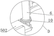
fig. 10 is an enlarged schematic structural view of a portion D of fig. 5 according to the present invention.
Illustration of the drawings:
1. a lower die holder; 2. an upper die holder; 3. a stripping mechanism; 301. an ejection ring; 302. a first spring; 303. a butting ring; 4. an ejection mechanism; 401. an electric push rod; 402. a fixed seat; 403. a driven gear ring; 404. a drive motor; 405. a drive gear; 406. a cutter thimble; 407. a housing base; 5. a cutting mechanism; 501. a movable seat; 502. cutting a cutter; 503. a butting rod; 504. a telescopic rod; 505. a second spring; 506. a fixed block; 507. adjusting the screw rod; 508. pulling the base; 509. a connecting rod; 510. pulling the block; 6. ejecting the needle; 7. an injection molding base; 8. separating the inner gate; 9. abutting against the triangular block; 10. a third spring; 11. an outer sprue bush; 12. a sliding housing.
Detailed Description
The technical solutions in the embodiments of the present invention will be clearly and completely described below with reference to the drawings in the embodiments of the present invention, and it is obvious that the described embodiments are only a part of the embodiments of the present invention, and not all of the embodiments. All other embodiments, which can be derived by a person skilled in the art from the embodiments given herein without making any creative effort, shall fall within the protection scope of the present invention.
Referring to fig. 1-2 and fig. 5-7, the present invention provides a technical solution: the utility model provides an injection mold with clout processing mechanism, includes die holder 1 and upper die base 2, 2 bottom fixed mounting of upper die base have the nozzle of moulding plastics, and mould plastics nozzle lateral wall cover and be equipped with slip shell 12, slip shell 12 sliding connection is in 2 both sides of upper die base, 12 bottom fixed mounting of slip shell have the seat of moulding plastics 7, 7 top fixedly connected with outer sprue bush 11 of the seat of moulding plastics, 11 lateral wall sliding connection of outer sprue bush have stripping mechanism 3, 11 inner chamber fixedly connected with separation inner gate 8 of outer sprue bush, 7 lateral wall fixed mounting of the seat of moulding plastics have a plurality of cutting mechanism 5 that are used for cutting runner material, 12 inner chamber fixed mounting of slip shell have rotatable ejection mechanism 4 for carry after rotating and drive 5 removals of cutting mechanism.
The implementation mode is specifically as follows: when a driving mechanism connected with the outside of the upper die holder 2 controls the upper die holder 2 to move downwards to be attached to the lower die holder 1, an injection nozzle in the upper die holder 2 can enter a separation inner gate 8 after a sliding shell 12 and the lower die holder 1 are fully pressed and slide, an external injection molding machine sends injection molding liquid into a space between the upper die holder 2 and a die core of the lower die holder 1 through the separation inner gate 8, when a product is required to be demolded after injection molding, when the upper die holder 2 is controlled to move upwards, in order to avoid residual materials in an outer gate sleeve 11, the front-end cutter ejector pins 406 can be driven to move inwards by the extension of the electric push rod 401 during working, the cutter ejector pins 406 can drive the movable seat 501 to move, the movable seat 501 can be driven to move by the output shaft of the driving motor 404 to drive the driving gear 405 to rotate, the driven toothed ring 405 can drive the inner-side meshed toothed ring 403 to rotate, the driven toothed ring 403 can drive the top of the movable push rod 401 to rotate, meanwhile, the movable seat can drive the movable seat to drive the movable push rod 401 to move in the axial direction of the gate, the movable seat to adjust the residual materials, and the axial direction of the residual materials, and the movable seat can be convenient for adjusting the product.
Referring to fig. 5-6, one end of the cutting tool 502, which is far away from the cutting edge, is fixedly connected with a pulling block 510, one side of the pulling block 510 is hinged with a connecting rod 509 through a pin shaft, the other end of the connecting rod 509 is hinged with a pulling seat 508 through a pin shaft, the top of the pulling seat 508 is rotatably connected with an adjusting screw rod 507 through a bearing and a rotating shaft, the top end of the adjusting screw rod 507 is fixedly connected with a handle, the outer side wall of the adjusting screw rod 507 is in threaded connection with a screw rod seat, the outer side wall of the screw rod seat is fixedly connected with a connecting seat, and the connecting seat is fixedly connected with the top of the moving seat 501.
The implementation mode is specifically as follows: through the cutting tool 502 of design, can be at the lead screw seat internal rotation and rebound through twisting accommodate the lead screw 507, accommodate the lead screw 507 removes and can stimulate bottom pull seat 508 rebound, pull seat 508 removal and can rotate around the round pin axle and stimulate connecting rod 509 to remove, connecting rod 509 drives bottom pull piece 510 rebound simultaneously, it can drive opposite side cutting tool 502 and rotate around inboard articulated round pin axle to stimulate piece 510 rebound, thereby can realize the regulation of sword angle is gone into to the front end through the rotation of cutting tool 502, improve the clout through the regulation to cutting angle and break away from the effect.
Referring to fig. 3 and 6, both sides of the moving base 501 are fixedly connected with a fixed block 506, one side of the fixed block 506 is fixedly connected with a telescopic rod 504, the other end of the telescopic rod 504 is fixedly connected with one side of the outer wall of the injection base 7, a second spring 505 for elastic force return is sleeved on the outer side wall of the telescopic rod 504, and both ends of the second spring 505 are fixedly connected with the outside of the injection base 7 and one side of the fixed block 506 at corresponding positions respectively.
The implementation mode specifically comprises the following steps: through the fixed block 506 and the telescopic link 504 of design, can extrude telescopic link 504 through both sides fixed block 506 when removing seat 501 and removing, can extrude outside second spring 505 when telescopic link 504 shortens, and second spring 505 can utilize self elasticity to improve the stability that removes seat 501 and remove, avoids excessively rocking to lead to influencing cutting stability.
Referring to fig. 2, 5-8 and 10, a butting rod 503 is fixedly connected to one side of the top of the hinged rod in the inner cavity of the movable seat 501, four sliding holes are formed in the top of the injection seat 7, an ejector pin 6 is slidably connected in the sliding holes, the ejector pin 6 is attached to the bottom of the stripper mechanism 3, a third spring 10 is sleeved on the outer side wall of the ejector pin 6, two ends of the third spring 10 are respectively fixedly connected to the tail end of the ejector pin 6 and the top of the sliding groove inner cavity on one side of the injection seat 7, the stripper mechanism 3 includes an ejector ring 301, the top of the ejector ring 301 is attached to the bottom of the external stepped ring of the separation inner gate 8, a first spring 302 is fixedly connected to the bottom of the ejector ring 301, the first spring 302 is sleeved on the outer side of the outer gate sleeve 11, a butting ring 303 is fixedly connected to the bottom of the first spring 302, triangular blocks 9 are fixedly connected to the periphery of the bottom of the butting ring 303, inclined surfaces of the bottoms of the triangular blocks 9 correspond to the top ends of the ejector pin 6, guide rods are fixedly connected to the top of the sliding shell 12, and the guide rods are slidably connected to the guide holes of the upper die holder 2.
The implementation mode is specifically as follows: through the ejector pin 6 of design, when removing seat 501 fully and moving, the inside butt pole 503 of removing seat 501 can contact with ejector pin 6 in the 7 spouts of seat of moulding plastics, ejector pin 6 can be under the extruded condition upwards slide by the atress, can extrude the third spring 10 that the outside cover was established through terminal rank dress portion extrusion when ejecting pin 6 removed, make after removing seat 501 removes, the third spring can utilize self elasticity to drive ejector pin 6 and reset, ejector pin 6 removes and can contact with top butt triangle 9, the third spring 9 removes and can drive ejector ring 301 rebound when can extrude the first spring 302 in top, ejector ring 301 removes and can drive inboard separation inner gate 8 rebound, can drive the casting clout after the cutting upwards separate with outer sprue cover 11 inboard when toper separation inner gate 8 upwards removes, wherein, separation inner gate 8 can cut horizontal position phase-match with cutting tool 502 after the position, guarantee that the clout after moulding plastics deviates from, and when separating inner gate 8 upwards fully and moving, make things convenient for the manipulator or the outside of centre gripping portion to shift out the casting clout after can be favorable to utilize ejector pin 6 to drive the ejector ring 301 that the outer needle resets after the first spring 302 again, thereby the ejector pin can be favorable to the ejection pin after the removal of separation inner gate 8 and the ejector pin is fallen to drive the stability after the ejector ring 11 again.
The working principle is as follows: when the injection molding machine is used, after a driving mechanism connected to the outside of the upper die holder 2 controls the upper die holder 2 to move downwards to be attached to the lower die holder 1, an injection molding nozzle in the upper die holder 2 enters a separation inner sprue 8 after a sliding shell 12 and the lower die holder 1 are fully pressed and slide, an external injection molding machine sends injection molding liquid into a space between the upper die holder 2 and a die core of the lower die holder 1 through the separation inner sprue 8, according to the arc surface angle of the top of a product, an adjusting screw 507 rotates in a screw holder and moves upwards, the adjusting screw 507 moves to pull a bottom pull seat 508 to move upwards, the pull seat 508 moves to rotate around a pin shaft and pull a connecting rod 509 to move, the connecting rod 509 drives a bottom pull block 510 to move upwards, the pull block 510 moves upwards to drive a cutting tool 502 on the other side to rotate around an inner hinged pin shaft, and the front end knife entering angle is adjusted;
an output shaft of a driving motor 404 rotates to drive a driving gear 405 to rotate, the driving gear 405 rotates to drive a driven gear ring 403 meshed with the inner side to rotate, the driven gear ring 403 rotates to drive a top fixing seat 402 and an electric push rod 401 to move, and the electric push rod 401 moves to be in contact with moving seats 501 in different lateral positions;
when the product is subjected to demolding after injection molding, the upper die base 2 is controlled to move upwards, in order to avoid residual materials in the outer sprue bush 11, the electric push rod 401 extends to drive the front-end cutter ejector pin 406 to move inwards when working, the cutter ejector pin 406 moves to drive the moving base 501 to move, the moving base 501 moves to drive the front-end cutter 502 to contact with the outer sprue bush 11 and the residual materials on the inner side of the separation inner sprue 8, and the cutter 502 cuts off the sprue residual materials and the product;
when the movable seat 501 moves sufficiently, the abutting rod 503 inside the movable seat 501 contacts with the ejector pin 6 in the sliding groove of the injection molding seat 7, the ejector pin 6 slides upwards under the downward stress under the extrusion condition, the ejector pin 6 moves to contact with the top abutting triangular block 9, the abutting triangular block 9 moves to extrude the ejector ring 301 driven by the first top spring 302, the ejector ring 301 moves to drive the inner side separation inner gate 8 to move upwards, the tapered separation inner gate 8 moves upwards to drive the cut casting remainder to be separated upwards from the inner side of the outer gate sleeve 11, wherein the horizontal position of the bottom side of the separation inner gate 8 is matched with the cutting horizontal position of the cutting tool 502 after falling, and the remainder is separated.
The above description is only for the preferred embodiment of the present invention, but the scope of the present invention is not limited thereto, and any person skilled in the art should be considered to be within the technical scope of the present invention, and the technical solutions and the inventive concepts thereof according to the present invention should be equivalent or changed within the scope of the present invention.
Claims (8)
1. The utility model provides an injection mold with clout processing mechanism, includes die holder (1) and upper die base (2), its characterized in that, upper die base (2) bottom fixed mounting has the nozzle of moulding plastics, and moulds plastics nozzle lateral wall cover and be equipped with slip shell (12), slip shell (12) sliding connection is in upper die base (2) both sides, slip shell (12) bottom fixed mounting has the seat (7) of moulding plastics, mould plastics seat (7) top fixedly connected with outer sprue cover (11), outer sprue cover (11) lateral wall sliding connection has stripper mechanism (3), runner (8) in outer sprue cover (11) inner chamber fixedly connected with separation, mould plastics seat (7) lateral wall fixed mounting have a plurality of cutting mechanism (5) that are used for cutting sprue material, slip shell (12) inner chamber fixed mounting has rotatable ejection mechanism (4) for carry after the rotation and drive cutting mechanism (5) and remove.
2. The injection mold with the excess material processing mechanism according to claim 1, wherein the ejection mechanism (4) comprises a shell seat (407), the shell seat (407) is rotatably connected to an inner cavity of the sliding shell (12), a driven gear ring (403) is fixedly connected to an outer side wall of the shell seat (407), a driving gear (405) is engaged with one side of the driven gear ring (403), a driving motor (404) is fixedly connected to a top of the driving gear (405), the driving motor (404) is fixedly mounted at a top of the inner cavity of the sliding shell (12), a fixing seat (402) is fixedly connected to a top of the inner cavity of the shell seat (407), an electric push rod (401) is fixedly connected to one side of the inner cavity of the fixing seat (402), a cutter ejector pin (406) is fixedly connected to a front end of the electric push rod (401), and the cutter ejector pin (406) is slidably connected to a through hole formed in the inner cavity of the shell seat (407).
3. The injection mold with the excess material processing mechanism as claimed in claim 1, wherein the cutting mechanism (5) comprises a movable seat (501), the movable seat (501) is slidably connected in a sliding groove formed in the outer side wall of the injection seat (7), a cutting tool (502) is rotatably connected to the inner cavity of the movable seat (501) through a pin shaft, and the tail end of the cutting tool (502) extends to the outside of the fixed seat (402).
4. The injection mold with the excess material processing mechanism as claimed in claim 3, wherein both sides of the movable seat (501) are fixedly connected with a fixed block (506), one side of the fixed block (506) is fixedly connected with a telescopic rod (504), the other end of the telescopic rod (504) is fixedly connected with one side of the outer wall of the injection seat (7), the outer side wall of the telescopic rod (504) is sleeved with a second spring (505) for elastic force resetting, and two ends of the second spring (505) are respectively fixedly connected with the outside of the injection seat (7) and one side of the fixed block (506) in corresponding positions.
5. The injection mold with the excess material processing mechanism is characterized in that one end, far away from the cutting edge, of the cutting tool (502) is fixedly connected with a pulling block (510), one side of the pulling block (510) is hinged with a connecting rod (509) through a pin shaft, the other end of the connecting rod (509) is hinged with a pulling seat (508) through a pin shaft, the top of the pulling seat (508) is rotatably connected with an adjusting screw rod (507) through a bearing and a rotating shaft, the top end of the adjusting screw rod (507) is fixedly connected with a handle, the outer side wall of the adjusting screw rod (507) is in threaded connection with a screw rod seat, the outer side wall of the screw rod seat is fixedly connected with a connecting seat, and the connecting seat is fixedly connected with the top of the moving seat (501).
6. The injection mold with the excess material processing mechanism according to claim 4, wherein the inner cavity of the movable seat (501) is fixedly connected with a butting rod (503) at one side of the top of the hinge rod, four sliding holes are formed in the top of the injection seat (7), an ejector pin (6) is slidably connected in the sliding holes, the ejector pin (6) is attached to the bottom of the stripping mechanism (3), a third spring (10) is sleeved on the outer side wall of the ejector pin (6), and two ends of the third spring (10) are respectively fixedly connected with the end of the ejector pin (6) and the top of the sliding groove inner cavity at one side of the injection seat (7).
7. The injection mold with the excess material processing mechanism is characterized in that the material removing mechanism (3) comprises an ejection ring (301), the top of the ejection ring (301) is attached to the bottom side of an external step ring of the separated inner sprue (8), a first spring (302) is fixedly connected to the bottom of the ejection ring (301), the first spring (302) is sleeved outside an outer sprue bush (11), a butting ring (303) is fixedly connected to the bottom end of the first spring (302), a butting triangular block (9) is fixedly connected to the periphery of the bottom of the butting ring (303), and an inclined surface of the bottom of the butting triangular block (9) corresponds to the top end of the ejector pin (6).
8. The injection mold with the excess material processing mechanism as claimed in claim 1, wherein the sliding shell (12) is fixedly connected with guide rods on both sides of the top thereof, and the guide rods are slidably connected in guide holes formed in the top of the upper mold base (2).
Priority Applications (1)
| Application Number | Priority Date | Filing Date | Title |
|---|---|---|---|
| CN202211314832.1A CN115648549A (en) | 2022-10-26 | 2022-10-26 | Injection mold with clout processing mechanism |
Applications Claiming Priority (1)
| Application Number | Priority Date | Filing Date | Title |
|---|---|---|---|
| CN202211314832.1A CN115648549A (en) | 2022-10-26 | 2022-10-26 | Injection mold with clout processing mechanism |
Publications (1)
| Publication Number | Publication Date |
|---|---|
| CN115648549A true CN115648549A (en) | 2023-01-31 |
Family
ID=84992380
Family Applications (1)
| Application Number | Title | Priority Date | Filing Date |
|---|---|---|---|
| CN202211314832.1A Withdrawn CN115648549A (en) | 2022-10-26 | 2022-10-26 | Injection mold with clout processing mechanism |
Country Status (1)
| Country | Link |
|---|---|
| CN (1) | CN115648549A (en) |
Cited By (1)
| Publication number | Priority date | Publication date | Assignee | Title |
|---|---|---|---|---|
| CN119058028A (en) * | 2024-11-05 | 2024-12-03 | 天津奥博特塑胶电子有限公司 | Injection mold and molding process of wire harness fixing frame |
-
2022
- 2022-10-26 CN CN202211314832.1A patent/CN115648549A/en not_active Withdrawn
Cited By (2)
| Publication number | Priority date | Publication date | Assignee | Title |
|---|---|---|---|---|
| CN119058028A (en) * | 2024-11-05 | 2024-12-03 | 天津奥博特塑胶电子有限公司 | Injection mold and molding process of wire harness fixing frame |
| CN119058028B (en) * | 2024-11-05 | 2025-01-07 | 天津奥博特塑胶电子有限公司 | Injection mold and molding process of wire harness fixing frame |
Similar Documents
| Publication | Publication Date | Title |
|---|---|---|
| CN217891733U (en) | Plastic mould rapid demoulding device | |
| CN222372218U (en) | Injection molding machine die for producing plastic frames | |
| CN211616411U (en) | Automobile part injection mold | |
| CN213412769U (en) | Material ejection mechanism for die machining | |
| CN221622878U (en) | PVC part injection molding mould | |
| CN115157550A (en) | Secondary forming injection mold | |
| CN113334695A (en) | Portable demolding ejection structure of mold | |
| CN217621985U (en) | Rotary automatic sprue cutting mechanism for injection mold | |
| CN117799124A (en) | Injection mold straight core-ejecting oblique core-pulling differential linkage demoulding device | |
| CN214000390U (en) | Plastic helmet mold convenient for demolding | |
| CN216423227U (en) | Multidirectional online group injection molding automation equipment | |
| CN110039720A (en) | The injection mold of energy automatic and accurate feeding | |
| CN213728898U (en) | Light alloy stamping die convenient to ejection of compact | |
| CN214294221U (en) | Injection mold is used in production of air-out bars | |
| CN112549461A (en) | Printer housing cold glue opening mold based on semi-hot runner latent sliding block | |
| CN114103029A (en) | Ejection die after rotary core pulling | |
| CN211251181U (en) | Feeding bottle plastic cap production mold convenient to demolding | |
| CN222346181U (en) | Environment-friendly plastic molding die | |
| CN221161374U (en) | Runner cutting device for plastic injection molding part for vehicle | |
| CN223890407U (en) | Mould runner cuts mechanism | |
| CN112388871A (en) | High-precision splicing type plastic mold | |
| CN111055455A (en) | Injection mold convenient to take off material | |
| CN211994033U (en) | Automatic plastic products mould of drawing of patterns | |
| CN212764528U (en) | Injection mold of worm | |
| CN213860493U (en) | Multi-cavity injection mold core-pulling mechanism |
Legal Events
| Date | Code | Title | Description |
|---|---|---|---|
| PB01 | Publication | ||
| PB01 | Publication | ||
| SE01 | Entry into force of request for substantive examination | ||
| SE01 | Entry into force of request for substantive examination | ||
| WW01 | Invention patent application withdrawn after publication |
Application publication date: 20230131 |
|
| WW01 | Invention patent application withdrawn after publication |