CN115647919A - Secondary rolling electric automobile silicon steel production equipment and production method thereof - Google Patents
Secondary rolling electric automobile silicon steel production equipment and production method thereof Download PDFInfo
- Publication number
- CN115647919A CN115647919A CN202211392967.XA CN202211392967A CN115647919A CN 115647919 A CN115647919 A CN 115647919A CN 202211392967 A CN202211392967 A CN 202211392967A CN 115647919 A CN115647919 A CN 115647919A
- Authority
- CN
- China
- Prior art keywords
- block
- silicon steel
- rod
- wall
- fixedly connected
- Prior art date
- Legal status (The legal status is an assumption and is not a legal conclusion. Google has not performed a legal analysis and makes no representation as to the accuracy of the status listed.)
- Pending
Links
Images




Landscapes
- Cleaning In General (AREA)
Abstract
Description
技术领域technical field
本发明涉及硅钢加工技术领域,具体为一种二次轧制电动汽车用硅钢生产设备及其生产方法。The invention relates to the technical field of silicon steel processing, in particular to a secondary rolling silicon steel production equipment for electric vehicles and a production method thereof.
背景技术Background technique
电动汽车(BEV)是指以车载电源为动力,用电机驱动车轮行驶,符合道路交通、安全法规各项要求的车辆,由于对环境影响相对传统汽车较小,其前景被广泛看好。Electric vehicles (BEV) refer to vehicles powered by vehicle-mounted power supplies and motor-driven wheels that meet the requirements of road traffic and safety regulations. Because they have less impact on the environment than traditional vehicles, their prospects are widely optimistic.
电动汽车在进行生产过程中,驱动电机会使用到硅钢,硅钢含硅为1.0~4.5%,含碳量小于0.08%的硅合金钢叫做硅钢,它具有导磁率高、矫顽力低、电阻系数大等特性,因而磁滞损失和涡流损失都小,主要用作电机、变压器、电器以及电工仪表中的磁性材料,为了制造电器时满足冲剪加工的需要,还要求有一定的塑性,为了提高磁感性能,降低磁滞损耗,要求其有害杂质含量越低越好,并要求板型平整,表面质量好,硅钢以铁芯损耗(简称铁损)和磁感应强度(简称磁感)作为产品磁性保证值,硅钢铁损低可节省大量电能,延长电机和变压器工作运转时间和简化冷却系统,由于硅钢铁损造成的电量损失占全年发电量的2.5%~4.5%,其中变压器铁损约占50%,1~100kW小型电机约占30%,日光灯镇流器约占15%。In the production process of electric vehicles, the drive motor will use silicon steel. Silicon steel contains 1.0-4.5% silicon and silicon alloy steel with a carbon content of less than 0.08%. It has high magnetic permeability, low coercive force, and resistivity. Large and other characteristics, so hysteresis loss and eddy current loss are small, mainly used as magnetic materials in motors, transformers, electrical appliances and electrical instruments. In order to meet the needs of punching and shearing processing when manufacturing electrical appliances, a certain degree of plasticity is also required. Magnetic induction performance, reducing hysteresis loss, requires the lower the content of harmful impurities, the better, and requires flat plate shape and good surface quality. Silicon steel uses core loss (abbreviated as iron loss) and magnetic induction intensity (abbreviated as magnetic induction) as the magnetic properties of the product. Guaranteed value, low silicon steel loss can save a lot of power, prolong the working time of motors and transformers and simplify the cooling system, the power loss caused by silicon steel loss accounts for 2.5% to 4.5% of the annual power generation, of which the transformer iron loss accounts for about 50%, 1 ~ 100kW small motors accounted for about 30%, fluorescent lamp ballasts accounted for about 15%.
但现有处理设备存在以下不足:However, the existing processing equipment has the following disadvantages:
现有电动汽车用硅钢在加工时,如CN204052687U,工作时,硅钢片横剪线设备运行时,当一侧卷绕轴上缠绕的片料消耗完毕,光电感应开关感应卷绕轴送料状况并发出信号,液压马达接收该信号控制该卷绕轴作180度反向旋转至初始位置,同时所述气缸松开卷绕轴的锁紧状态,所述光电接近开关控制卷绕装置对准送料装置进行送料切换的角度调整,令片料耗尽的那一侧卷绕轴断开与送料装置进料口连接,令另一侧卷绕轴对准送料装置的进料口,所述气缸在光电接近开关完成角度调整后锁紧角度,完成卷绕装置和送料装置的送料切换。工作人员在硅钢片横剪线工作的同时对已耗尽片料且反向旋转至初始位置的卷绕轴上添加新片料,但是硅钢在进行加工运送过程中,硅钢表面容易沾染一些颗粒物污渍,在加工过程中,污渍受到挤压后容易造成硅钢表凹陷变形的现象,导致后续裁剪出的物料无法使用的情况,对此需进行改进。When the existing silicon steel for electric vehicles is being processed, such as CN204052687U, when the silicon steel sheet cross-cutting line equipment is running, when the sheet material wound on one side of the winding shaft is consumed, the photoelectric sensor switch senses the feeding status of the winding shaft and sends out signal, the hydraulic motor receives the signal and controls the winding shaft to reversely rotate 180 degrees to the initial position, and at the same time, the cylinder releases the locking state of the winding shaft, and the photoelectric proximity switch controls the winding device to align with the feeding device. Adjust the angle of feeding switch, so that the winding shaft on the side where the sheet material is exhausted is disconnected from the feeding port of the feeding device, and the winding shaft on the other side is aligned with the feeding port of the feeding device. After the switch completes the angle adjustment, the angle is locked, and the feeding switch between the winding device and the feeding device is completed. While working on the silicon steel sheet cross-cutting line, the staff add new sheets to the winding shaft that has exhausted the sheets and reversely rotated to the initial position. However, during the processing and transportation of silicon steel, the surface of silicon steel is easily contaminated with some particulate matter. In the process of processing, the stains are likely to cause the phenomenon of denting and deformation of the silicon steel surface after being squeezed, resulting in the unusable situation of the subsequent cut materials, which needs to be improved.
所以我们提出了一种二次轧制电动汽车用硅钢生产设备及其生产方法,以便于解决上述中提出的问题。Therefore, we propose a secondary rolling silicon steel production equipment for electric vehicles and a production method thereof, in order to solve the above-mentioned problems.
发明内容Contents of the invention
本发明的目的在于提供一种二次轧制电动汽车用硅钢生产设备及其生产方法,当需要使用设备时,推动推杆,推杆带动卡杆进行移动,第一弹簧受力形变产生弹力,卡杆失去对矩形块表面插孔的束缚,在固定块中推动移动板和毛刷板,移动至一定位置时,松开推杆的,第一弹簧释放弹力,带动卡杆进行复位,使卡杆插设在矩形块表面的插孔中,硅钢在运送时,两组毛刷板即可进行清理,以解决上述背景技术提出的问题。The object of the present invention is to provide a silicon steel production equipment for secondary rolling electric vehicles and its production method. When the equipment needs to be used, the push rod is pushed, and the push rod drives the clamping rod to move, and the first spring deforms under force to generate elastic force. The lever loses its bondage to the socket on the surface of the rectangular block, and pushes the movable plate and the brush plate in the fixed block. The rod is inserted into the socket on the surface of the rectangular block, and when the silicon steel is transported, two sets of brush plates can be cleaned to solve the problems raised by the above-mentioned background technology.
为实现上述目的,本发明提供如下技术方案:一种二次轧制电动汽车用硅钢生产设备及其生产方法,包括送料器,所述送料器的一侧设置有支架,所述支架的表面设置有整理室,所述整理室的内壁设置有多个压轴,所述支架的表面设置有裁剪室,所述支架的表面设置有去污装置,所述去污装置包括固定块,所述固定块的个数有两个,两个所述固定块与支架的表面固定连接,所述固定块的表面开设有两个矩形孔,所述矩形孔的内壁滑动连接有移动板,所述移动板的一侧表面设置有毛刷板,所述移动板和毛刷板共有两组,通过设置两组移动板和毛刷板,可以在运送硅钢时对硅钢的两面进行去污处理,降低了设备在生产时,表面在运送时沾染颗粒物污渍导致在压平时出现变形影响后续裁剪使用的情况。In order to achieve the above object, the present invention provides the following technical solutions: a secondary rolling of silicon steel production equipment for electric vehicles and a production method thereof, including a feeder, a support is provided on one side of the feeder, and a support is provided on the surface of the support. There is a finishing room, the inner wall of the finishing room is provided with a plurality of finale shafts, the surface of the support is provided with a cutting room, the surface of the support is provided with a decontamination device, and the decontamination device includes a fixed block, and the fixed block There are two, the two fixed blocks are fixedly connected to the surface of the bracket, the surface of the fixed block is provided with two rectangular holes, the inner wall of the rectangular hole is slidingly connected with a moving plate, and the moving plate One side surface is provided with a brush plate, and there are two sets of the moving plate and the brush plate. By setting the two sets of moving plate and the brush plate, the two sides of the silicon steel can be decontaminated when the silicon steel is transported, reducing the equipment’s operating time. During production, the surface is contaminated with particulate matter during transportation, resulting in deformation during flattening and affecting subsequent cutting and use.
优选的,所述移动板的表面开设有两个滑孔,所述滑孔的内壁滑动连接有卡杆,所述卡杆的横截面呈U形,所述固定块靠近卡杆的一侧表面固定连接有矩形块,所述矩形块的表面开设有两个插孔,所述矩形块与插孔的内壁卡接,通过卡杆配合矩形块表面的两个插孔,可以对移动板和毛刷板进行限制定位,便于两组毛刷板对硅钢表面进行清理。Preferably, two sliding holes are opened on the surface of the moving plate, the inner wall of the sliding hole is slidably connected with a clamping rod, the cross section of the clamping rod is U-shaped, and the side surface of the fixed block is close to the clamping rod A rectangular block is fixedly connected, and the surface of the rectangular block is provided with two sockets, and the rectangular block is engaged with the inner wall of the socket, and the movable plate and the wool The brush plate is limited and positioned, which is convenient for two sets of brush plates to clean the surface of the silicon steel.
优选的,所述卡杆与移动板表面滑孔内壁相对应的一侧固定连接有第一弹簧,所述第一弹簧的个数有两个,通过设置第一弹簧,便于控制卡杆进行复位,同时提高了卡杆对矩形块表面插孔的束缚效果。Preferably, a first spring is fixedly connected to the side corresponding to the inner wall of the sliding hole on the surface of the moving plate, and the number of the first springs is two. By setting the first spring, it is convenient to control the reset of the locking rod , and at the same time improve the binding effect of the clamping rod on the jack on the surface of the rectangular block.
优选的,所述卡杆的一侧表面固定连接有推杆,所述推杆的个数有两个,所述推杆呈圆柱形设置,通过设置推杆,便于控制卡杆进行移动,提高整体易用性。Preferably, one side surface of the clamping rod is fixedly connected with a push rod, and there are two push rods, and the push rods are arranged in a cylindrical shape. By setting the push rod, it is convenient to control the movement of the clamping rod and improve the Overall ease of use.
优选的,所述毛刷板靠近移动板的一侧设置有辅助装置,所述辅助装置包括插块,所述插块的个数有两个,两个所述插块与毛刷板的表面固定连接,所述移动板的两侧表面均固定连接有空心套,所述插块与空心套的内壁卡接,所述空心套的内壁开设有滑行孔,所述滑行孔的内壁滑动连接有滑块,所述插块的表面开设有卡槽,所述滑块卡槽的内壁卡接,所述滑块的表面固定连接有控制杆,通过控制杆配合滑块,可以将插块束缚在空心套中,方便后续对毛刷板进行清理更换,降低了设备长时间清理导致自身受污染影响后续清理效果的情况。Preferably, an auxiliary device is provided on the side of the brush plate close to the moving plate, and the auxiliary device includes an insert block. There are two insert blocks, and the two insert blocks are connected to the surface of the brush plate. fixed connection, both sides of the moving plate are fixedly connected with a hollow sleeve, the insert block is clamped with the inner wall of the hollow sleeve, the inner wall of the hollow sleeve is provided with a sliding hole, and the inner wall of the sliding hole is slidably connected with Slider, the surface of the insert is provided with a card slot, the inner wall of the slide slot is snapped, the surface of the slider is fixedly connected with a control rod, and the insert can be bound to the slider through the control rod. The hollow sleeve is convenient for subsequent cleaning and replacement of the brush plate, which reduces the situation that the equipment itself will be polluted and affect the subsequent cleaning effect due to long-term cleaning.
优选的,所述滑块与空心套表面滑行孔内壁相对应的一侧固定连接有第二弹簧,所述第二弹簧的个数有两个,通过设置第二弹簧,便于控制滑块进行复位,同时提高了滑块对插块表面卡槽的束缚效果。Preferably, a second spring is fixedly connected to the side of the slider corresponding to the inner wall of the sliding hole on the surface of the hollow sleeve, and the number of the second springs is two. By setting the second spring, it is convenient to control the slider to reset , while improving the binding effect of the slider on the slot on the surface of the insert.
优选的,所述裁剪室的表面设置有限位装置,所述限位装置包括固定座,所述固定座的个数有两个,两个所述固定座与裁剪室的表面固定连接,所述固定座的表面开设有圆形孔,所述圆形孔的内壁滑动连接有移动杆,所述移动杆的一端固定连接有限位板,所述固定座的内壁开设有移动槽,所述移动槽的内壁滑动连接有卡块,所述移动杆的表面开设有多个限位槽,所述卡块与限位槽的内壁卡接,通过卡块配合多个限位槽,可以使限位板对硅钢裁剪时进行限位,降低了设备运送时出现偏移导致裁剪出错导致浪费的情况。Preferably, a limiting device is provided on the surface of the cutting chamber, and the limiting device includes a fixing seat, and there are two fixing seats, and the two fixing seats are fixedly connected with the surface of the cutting room, and the The surface of the fixed seat is provided with a circular hole, the inner wall of the circular hole is slidably connected with a moving rod, one end of the movable rod is fixedly connected with the limiting plate, and the inner wall of the fixed seat is provided with a moving groove, and the moving groove The inner wall of the sliding rod is connected with a block, and the surface of the moving rod is provided with a plurality of limit grooves, and the block is engaged with the inner wall of the limit groove, and the limit plate can be made Limiting the cutting of silicon steel reduces the situation of misalignment and waste caused by cutting when the equipment is transported.
优选的,所述固定座的表面开设有两个连接孔,所述卡块的表面固定连接有两个连接杆,所述连接杆的一端固定连接有按压块,通过按压块配合连接杆,可以控制卡块进行移动,方便对设备进行调节。Preferably, two connecting holes are opened on the surface of the fixing seat, two connecting rods are fixedly connected to the surface of the clamping block, and a pressing block is fixedly connected to one end of the connecting rod, and the pressing block can be matched with the connecting rod to The control block can be moved to facilitate the adjustment of the equipment.
优选的,所述连接杆的表面套设有第三弹簧,所述第三弹簧的两端分别与按压块和固定座的表面固定连接,通过设置第三弹簧,便于控制卡块进行复位,同时提高了卡块的束缚效果。Preferably, a third spring is sheathed on the surface of the connecting rod, and the two ends of the third spring are respectively fixedly connected to the surface of the pressing block and the fixing seat. By setting the third spring, it is convenient to control the block to reset, and at the same time Increased the binding effect of blocks.
一种二次轧制电动汽车用硅钢生产设备及其生产方法,步骤如下:A kind of secondary rolling electric vehicle silicon steel production equipment and production method thereof, the steps are as follows:
步骤一:当需要使用设备时,推动推杆,推杆带动卡杆进行移动,第一弹簧受力形变产生弹力,卡杆失去对矩形块表面插孔的束缚,在固定块中推动移动板和毛刷板,移动至一定位置时,松开推杆的,第一弹簧释放弹力,带动卡杆进行复位,使卡杆插设在矩形块表面的插孔中,硅钢在运送时,两组毛刷板即可进行清理;Step 1: When the equipment needs to be used, push the push rod, the push rod drives the clamping rod to move, the first spring deforms under force to generate elastic force, the clamping rod loses its restraint on the socket on the surface of the rectangular block, and pushes the moving plate and the clamping rod in the fixed block When the brush plate moves to a certain position, release the push rod, the first spring releases the elastic force, and drives the clamp rod to reset, so that the clamp rod is inserted into the socket on the surface of the rectangular block. When the silicon steel is transported, two sets of hair Brush the board to clean it;
步骤二:当需要拆卸清理时,推动控制杆,控制杆带动滑块进行移动,第二弹簧受力形变产生弹力,滑块失去对连接块表面卡槽的束缚,将连接块从空心套中拔出,即可对毛刷板进行拆卸清理;Step 2: When it needs to be disassembled and cleaned, push the control lever, the control lever drives the slider to move, the second spring deforms under force to generate elastic force, the slider loses its bondage to the groove on the surface of the connecting block, and pulls the connecting block out of the hollow sleeve out, the brush plate can be disassembled and cleaned;
步骤三:当需要使用设备时,推动按压块和连接杆,连接杆带动卡块进行移动,第三弹簧受力形变产生弹力,卡块失去对移动杆表面限位槽的束缚效果,在固定座中推动移动杆和限位板,两组限位板可以对硅钢进行限制,松开按压块,第三弹簧释放弹力,带动卡块进行复位,卡块插设在移动杆表面相对应的限位槽中。Step 3: When the device needs to be used, push the pressing block and the connecting rod, the connecting rod drives the block to move, the third spring deforms under force to generate elastic force, the block loses its restraining effect on the limit groove on the surface of the moving rod, and is placed on the fixed seat Push the moving rod and the limit plate in the middle, the two sets of limit plates can limit the silicon steel, release the pressing block, the third spring releases the elastic force, drives the block to reset, and the block is inserted in the corresponding limit on the surface of the moving rod in the slot.
与现有技术相比,本发明的有益效果是:Compared with prior art, the beneficial effect of the present invention is:
1、本发明通过设置去污装置,当需要使用设备时,推动推杆,推杆带动卡杆进行移动,第一弹簧受力形变产生弹力,卡杆失去对矩形块表面插孔的束缚,在固定块中推动移动板和毛刷板,移动至一定位置时,松开推杆的,第一弹簧释放弹力,带动卡杆进行复位,使卡杆插设在矩形块表面的插孔中,硅钢在运送时,两组毛刷板即可进行清理,通过设置去污装置,便于对硅钢表面进行清理,可以有效地降低了硅钢在运送加工时表面容易沾染一些颗粒物,颗粒物受到挤压容易造成硅钢变形的现象,降低了硅钢后续裁剪后成品报废的情况,进而提高了设备整体的稳定性。1. In the present invention, by setting the decontamination device, when the equipment needs to be used, the push rod is pushed, and the push rod drives the clamping rod to move, the first spring deforms under force to generate elastic force, and the clamping rod loses the bondage to the socket on the surface of the rectangular block, Push the moving plate and the brush plate in the fixed block, when they move to a certain position, release the push rod, the first spring releases the elastic force, and drives the clamping rod to reset, so that the clamping rod is inserted into the socket on the surface of the rectangular block, silicon steel During transportation, two sets of brush plates can be cleaned. By setting up a decontamination device, it is convenient to clean the surface of the silicon steel, which can effectively reduce the surface of the silicon steel from being easily contaminated with some particles during transportation and processing. The phenomenon of deformation reduces the scrapping of finished products after subsequent cutting of silicon steel, thereby improving the overall stability of the equipment.
2、本发明通过设置辅助装置,当需要拆卸清理时,推动控制杆,控制杆带动滑块进行移动,第二弹簧受力形变产生弹力,滑块失去对连接块表面卡槽的束缚,将连接块从空心套中拔出,即可对毛刷板进行拆卸清理,通过设置辅助装置,便于对设备进行拆卸清理,可以有效地降低了设备在清理时,表面容易沾染污渍的现象,降低了设备后续清理效果差的情况,进而提高了设备整体的易用性。2. The present invention sets the auxiliary device. When it needs to be disassembled and cleaned, the control lever is pushed, and the control lever drives the slider to move. The second spring deforms under force to generate elastic force. The brush plate can be disassembled and cleaned by pulling out the block from the hollow sleeve. By setting the auxiliary device, it is convenient to disassemble and clean the equipment, which can effectively reduce the phenomenon that the surface of the equipment is easy to be stained with dirt during cleaning, and reduce the equipment cost. The subsequent cleaning effect is poor, which in turn improves the overall ease of use of the equipment.
3、本发明通过设置限位装置,当需要使用设备时,推动按压块和连接杆,连接杆带动卡块进行移动,第三弹簧受力形变产生弹力,卡块失去对移动杆表面限位槽的束缚效果,在固定座中推动移动杆和限位板,两组限位板可以对硅钢进行限制,松开按压块,第三弹簧释放弹力,带动卡块进行复位,卡块插设在移动杆表面相对应的限位槽中,即可完成使用,通过设置限位装置,便于硅钢运送时进行限制,可以有效地降低了设备在运送时出现偏移,造成硅钢磨损的现象,降低了设备后续裁剪后不合格的情况,进而提高了设备整体的稳定性。3. In the present invention, by setting the limit device, when the equipment needs to be used, push the pressing block and the connecting rod, the connecting rod drives the block to move, the third spring deforms under force to generate elastic force, and the block loses the limit groove on the surface of the moving rod The binding effect, push the moving rod and the limit plate in the fixed seat, the two sets of limit plates can limit the silicon steel, loosen the pressing block, the third spring releases the elastic force, drives the block to reset, and the block is inserted in the moving It can be used in the limit groove corresponding to the surface of the rod. By setting the limit device, it is convenient to limit the silicon steel during transportation, which can effectively reduce the deviation of the equipment during transportation, which will cause the silicon steel to wear, and reduce the equipment cost. The unqualified situation after subsequent cutting improves the overall stability of the equipment.
附图说明Description of drawings
图1为本发明一种二次轧制电动汽车用硅钢生产设备及其生产方法中主视结构立体图;Fig. 1 is a three-dimensional view of the main view structure in a kind of secondary rolling electric vehicle silicon steel production equipment and production method thereof of the present invention;
图2为本发明一种二次轧制电动汽车用硅钢生产设备及其生产方法中侧视结构立体图;Fig. 2 is a side view structural stereogram in a kind of secondary rolling electric vehicle silicon steel production equipment and production method thereof of the present invention;
图3为本发明一种二次轧制电动汽车用硅钢生产设备及其生产方法中去污装置结构立体图;3 is a three-dimensional view of the decontamination device structure in a kind of secondary rolling electric vehicle silicon steel production equipment and production method thereof of the present invention;
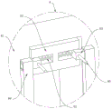
图4为本发明一种二次轧制电动汽车用硅钢生产设备及其生产方法为图3中A处结构放大立体图;Fig. 4 is a kind of secondary rolling electric vehicle silicon steel production equipment and its production method of the present invention, which is an enlarged perspective view of the structure at A in Fig. 3;
图5为本发明一种二次轧制电动汽车用硅钢生产设备及其生产方法为图3中B处结构放大立体图;Fig. 5 is a kind of secondary rolling electric vehicle silicon steel production equipment and its production method of the present invention, which is an enlarged perspective view of the structure at B in Fig. 3;
图6为本发明一种二次轧制电动汽车用硅钢生产设备及其生产方法中辅助装置剖视的结构立体图;Fig. 6 is a structural perspective view of a cross-section of an auxiliary device in a secondary rolling electric vehicle silicon steel production equipment and production method thereof of the present invention;
图7为本发明一种二次轧制电动汽车用硅钢生产设备及其生产方法中限位装置结构立体图;Fig. 7 is a three-dimensional view of the structure of the limiting device in the secondary rolling electric vehicle silicon steel production equipment and production method thereof of the present invention;
图8为本发明一种二次轧制电动汽车用硅钢生产设备及其生产方法中限位装置剖视结构立体图。Fig. 8 is a perspective view of the sectional structure of the limiting device in the secondary rolling silicon steel production equipment for electric vehicles and the production method thereof according to the present invention.
图中:1、送料器;2、支架;3、整理室;4、压轴;5、裁剪室;6、去污装置;61、固定块;62、移动板;63、毛刷板;64、矩形块;65、卡杆;66、推杆;67、第一弹簧;7、辅助装置;71、插块;72、空心套;73、滑块;74、控制杆;75、卡槽;76、第二弹簧;8、限位装置;81、固定座;82、移动杆;83、限位板;84、按压块;85、第三弹簧;86、卡块;87、连接杆。In the figure: 1. Feeder; 2. Bracket; 3. Finishing room; 4. Finale; 5. Cutting room; 6. Decontamination device; 61. Fixed block; 62. Moving plate; 63. Brush plate; 64. Rectangular block; 65, clamping rod; 66, push rod; 67, first spring; 7, auxiliary device; 71, inserting block; 72, hollow sleeve; 73, sliding block; 74, control rod; 75, card slot; 76 , the second spring; 8, the limit device; 81, the fixed seat; 82, the moving rod; 83, the limit plate; 84, the pressing block; 85, the third spring; 86, the block;
具体实施方式Detailed ways
下面将结合本发明实施例中的附图,对本发明实施例中的技术方案进行清楚、完整地描述,显然,所描述的实施条例仅仅是本发明一部分实施例,而不是全部的实施例。基于本发明中的实施例,本领域普通技术人员在没有做出创造性劳动前提下所获得的所有其他实施例,都属于本发明保护的范围。The following will clearly and completely describe the technical solutions in the embodiments of the present invention with reference to the accompanying drawings in the embodiments of the present invention. Obviously, the described implementation regulations are only some, not all, embodiments of the present invention. Based on the embodiments of the present invention, all other embodiments obtained by persons of ordinary skill in the art without making creative efforts belong to the protection scope of the present invention.
请参阅图1-8所示,本发明提供一种技术方案:一种二次轧制电动汽车用硅钢生产设备及其生产方法,包括送料器1,送料器1的一侧设置有支架2,支架2的表面设置有整理室3,整理室3的内壁设置有多个压轴4,支架2的表面设置有裁剪室5,支架2的表面设置有去污装置6。Please refer to Figures 1-8, the present invention provides a technical solution: a secondary rolling electric vehicle silicon steel production equipment and its production method, including a feeder 1, a support 2 is provided on one side of the feeder 1, A finishing
根据图3所示,去污装置6包括固定块61,固定块61的个数有两个,两个固定块61与支架2的表面固定连接,固定块61的表面开设有两个矩形孔,矩形孔的内壁滑动连接有移动板62,移动板62的一侧表面设置有毛刷板63,移动板62和毛刷板63共有两组,通过设置两组移动板62和毛刷板63,可以在运送硅钢时对硅钢的两面进行去污处理,降低了设备在生产时,表面在运送时沾染颗粒物污渍导致在压平时出现变形影响后续裁剪使用的情况。According to shown in Figure 3, decontamination device 6 comprises fixed
根据图4所示,移动板62的表面开设有两个滑孔,滑孔的内壁滑动连接有卡杆65,卡杆65的横截面呈U形,固定块61靠近卡杆65的一侧表面固定连接有矩形块64,矩形块64的表面开设有两个插孔,矩形块64与插孔的内壁卡接,通过卡杆65配合矩形块64表面的两个插孔,可以对移动板62和毛刷板63进行限制定位,便于两组毛刷板63对硅钢表面进行清理。According to Fig. 4, two sliding holes are provided on the surface of the moving
根据图4所示,卡杆65与移动板62表面滑孔内壁相对应的一侧固定连接有第一弹簧67,第一弹簧67的个数有两个,通过设置第一弹簧67,便于控制卡杆65进行复位,同时提高了卡杆65对矩形块64表面插孔的束缚效果。As shown in Figure 4, the
根据图4所示,卡杆65的一侧表面固定连接有推杆66,推杆66的个数有两个,推杆66呈圆柱形设置,通过设置推杆66,便于控制卡杆65进行移动,提高整体易用性。According to Fig. 4, push
根据图5-6所示,毛刷板63靠近移动板62的一侧设置有辅助装置7,辅助装置7包括插块71,插块71的个数有两个,两个插块71与毛刷板63的表面固定连接,移动板62的两侧表面均固定连接有空心套72,插块71与空心套72的内壁卡接,空心套72的内壁开设有滑行孔,滑行孔的内壁滑动连接有滑块73,插块71的表面开设有卡槽75,滑块73卡槽75的内壁卡接,滑块73的表面固定连接有控制杆74,通过控制杆74配合滑块73,可以将插块71束缚在空心套72中,方便后续对毛刷板63进行清理更换,降低了设备长时间清理导致自身受污染影响后续清理效果的情况。As shown in Figures 5-6, the side of the
根据图6所示,滑块73与空心套72表面滑行孔内壁相对应的一侧固定连接有第二弹簧76,第二弹簧76的个数有两个,通过设置第二弹簧76,便于控制滑块73进行复位,同时提高了滑块73对插块71表面卡槽75的束缚效果。As shown in Figure 6, the side corresponding to the inner wall of the sliding hole on the surface of the
根据图7-8所示,裁剪室5的表面设置有限位装置8,限位装置8包括固定座81,固定座81的个数有两个,两个固定座81与裁剪室5的表面固定连接,固定座81的表面开设有圆形孔,圆形孔的内壁滑动连接有移动杆82,移动杆82的一端固定连接有限位板83,固定座81的内壁开设有移动槽,移动槽的内壁滑动连接有卡块86,移动杆82的表面开设有多个限位槽,卡块86与限位槽的内壁卡接,通过卡块86配合多个限位槽,可以使限位板83对硅钢裁剪时进行限位,降低了设备运送时出现偏移导致裁剪出错导致浪费的情况。As shown in Figures 7-8, the surface of the cutting chamber 5 is provided with a limiting device 8, the limiting device 8 includes a fixed seat 81, and there are two fixed seats 81, and the two fixed seats 81 are fixed to the surface of the cutting chamber 5. Connect, the surface of the fixed seat 81 is provided with a circular hole, the inner wall of the circular hole is slidingly connected with a moving
根据图8所示,固定座81的表面开设有两个连接孔,卡块86的表面固定连接有两个连接杆87,连接杆87的一端固定连接有按压块84,通过按压块84配合连接杆87,可以控制卡块86进行移动,方便对设备进行调节。As shown in Figure 8, the surface of the fixing base 81 is provided with two connection holes, the surface of the
根据图8所示,连接杆87的表面套设有第三弹簧85,第三弹簧85的两端分别与按压块84和固定座81的表面固定连接,通过设置第三弹簧85,便于控制卡块86进行复位,同时提高了卡块86的束缚效果。As shown in Figure 8, the surface of the connecting rod 87 is covered with a
一种二次轧制电动汽车用硅钢生产设备及其生产方法,步骤如下:A kind of secondary rolling electric vehicle silicon steel production equipment and production method thereof, the steps are as follows:
步骤一:当需要使用设备时,推动推杆66,推杆66带动卡杆65进行移动,第一弹簧67受力形变产生弹力,卡杆65失去对矩形块64表面插孔的束缚,在固定块61中推动移动板62和毛刷板63,移动至一定位置时,松开推杆66的,第一弹簧67释放弹力,带动卡杆65进行复位,使卡杆65插设在矩形块64表面的插孔中,硅钢在运送时,两组毛刷板63即可进行清理;Step 1: When the device needs to be used, push the
步骤二:当需要拆卸清理时,推动控制杆74,控制杆74带动滑块73进行移动,第二弹簧76受力形变产生弹力,滑块73失去对连接块表面卡槽75的束缚,将连接块从空心套72中拔出,即可对毛刷板63进行拆卸清理;Step 2: When it needs to be disassembled and cleaned, push the
步骤三:当需要使用设备时,推动按压块84和连接杆87,连接杆87带动卡块86进行移动,第三弹簧85受力形变产生弹力,卡块86失去对移动杆82表面限位槽的束缚效果,在固定座81中推动移动杆82和限位板83,两组限位板83可以对硅钢进行限制,松开按压块84,第三弹簧85释放弹力,带动卡块86进行复位,卡块86插设在移动杆82表面相对应的限位槽中。Step 3: When the equipment needs to be used, push the pressing block 84 and the connecting rod 87, the connecting rod 87 drives the
其整个机构所达到的效果为:通过设置去污装置6,当需要使用设备时,推动推杆66,推杆66带动卡杆65进行移动,第一弹簧67受力形变产生弹力,卡杆65失去对矩形块64表面插孔的束缚,在固定块61中推动移动板62和毛刷板63,移动至一定位置时,松开推杆66的,第一弹簧67释放弹力,带动卡杆65进行复位,使卡杆65插设在矩形块64表面的插孔中,硅钢在运送时,两组毛刷板63即可进行清理,通过设置去污装置6,便于对硅钢表面进行清理,可以有效地降低了硅钢在运送加工时表面容易沾染一些颗粒物,颗粒物受到挤压容易造成硅钢变形的现象,降低了硅钢后续裁剪后成品报废的情况,进而提高了设备整体的稳定性,通过设置辅助装置7,当需要拆卸清理时,推动控制杆74,控制杆74带动滑块73进行移动,第二弹簧76受力形变产生弹力,滑块73失去对连接块表面卡槽75的束缚,将连接块从空心套72中拔出,即可对毛刷板63进行拆卸清理,通过设置辅助装置7,便于对设备进行拆卸清理,可以有效地降低了设备在清理时,表面容易沾染污渍的现象,降低了设备后续清理效果差的情况,进而提高了设备整体的易用性,通过设置限位装置8,当需要使用设备时,推动按压块84和连接杆87,连接杆87带动卡块86进行移动,第三弹簧85受力形变产生弹力,卡块86失去对移动杆82表面限位槽的束缚效果,在固定座81中推动移动杆82和限位板83,两组限位板83可以对硅钢进行限制,松开按压块84,第三弹簧85释放弹力,带动卡块86进行复位,卡块86插设在移动杆82表面相对应的限位槽中,即可完成使用,通过设置限位装置8,便于硅钢运送时进行限制,可以有效地降低了设备在运送时出现偏移,造成硅钢磨损的现象,降低了设备后续裁剪后不合格的情况,进而提高了设备整体的稳定性。The effect achieved by the whole mechanism is: by setting the decontamination device 6, when the equipment needs to be used, the
尽管参照前述实施例对本发明进行了详细的说明,对于本领域的技术人员来说,其依然可以对前述各实施例所记载的技术方案进行修改,或者对其中部分技术特征进行等同替换,凡在本发明的精神和原则之内,所做的任何修改、等同替换、改进等,均应包含在本发明的保护范围之内。Although the present invention has been described in detail with reference to the aforementioned embodiments, those skilled in the art can still modify the technical solutions described in the aforementioned embodiments, or perform equivalent replacements for some of the technical features. Within the spirit and principles of the present invention, any modifications, equivalent replacements, improvements, etc., shall be included in the protection scope of the present invention.
Claims (10)
Priority Applications (1)
| Application Number | Priority Date | Filing Date | Title |
|---|---|---|---|
| CN202211392967.XA CN115647919A (en) | 2022-11-08 | 2022-11-08 | Secondary rolling electric automobile silicon steel production equipment and production method thereof |
Applications Claiming Priority (1)
| Application Number | Priority Date | Filing Date | Title |
|---|---|---|---|
| CN202211392967.XA CN115647919A (en) | 2022-11-08 | 2022-11-08 | Secondary rolling electric automobile silicon steel production equipment and production method thereof |
Publications (1)
| Publication Number | Publication Date |
|---|---|
| CN115647919A true CN115647919A (en) | 2023-01-31 |
Family
ID=85015680
Family Applications (1)
| Application Number | Title | Priority Date | Filing Date |
|---|---|---|---|
| CN202211392967.XA Pending CN115647919A (en) | 2022-11-08 | 2022-11-08 | Secondary rolling electric automobile silicon steel production equipment and production method thereof |
Country Status (1)
| Country | Link |
|---|---|
| CN (1) | CN115647919A (en) |
Citations (10)
| Publication number | Priority date | Publication date | Assignee | Title |
|---|---|---|---|---|
| KR19980030307U (en) * | 1996-11-29 | 1998-08-17 | 양재신 | Conveyor Belt Cover Structure of Blanking Press Line |
| CN204052687U (en) * | 2014-01-27 | 2014-12-31 | 上海祯驰电气设备有限公司 | Silicon steel sheet is horizontal cuts process equipment |
| CN204052688U (en) * | 2014-01-27 | 2014-12-31 | 上海祯驰电气设备有限公司 | The horizontal shearing flow waterline of silicon steel sheet |
| CN107486419A (en) * | 2017-07-19 | 2017-12-19 | 重庆市翔聪机械制造有限公司 | A kind of pressing equipment cleaning mechanism |
| CN213224529U (en) * | 2020-12-15 | 2021-05-18 | 济南森阳机械有限公司 | Plate shearing machine with leveling function |
| WO2022082911A1 (en) * | 2020-10-22 | 2022-04-28 | 罗必锋 | Edge pressing device for automobile leather foot pad production |
| CN114713662A (en) * | 2022-04-19 | 2022-07-08 | 江西星铝科技有限公司 | Straightening machine for surface flatness of aluminum alloy template |
| CN115069796A (en) * | 2022-06-13 | 2022-09-20 | 安徽成骏家居制造有限公司 | High specific stiffness foamed aluminum sandwich plate manufacturing equipment and foamed aluminum sandwich plate processing technology |
| CN217577328U (en) * | 2022-05-27 | 2022-10-14 | 东莞市通成彩钢板有限公司 | Color plate rock wool feeding machine |
| CN217666671U (en) * | 2022-06-29 | 2022-10-28 | 蚌埠市天诺机械设备股份有限公司 | Milling machine metal centralized storage device for sensor base machining |
-
2022
- 2022-11-08 CN CN202211392967.XA patent/CN115647919A/en active Pending
Patent Citations (10)
| Publication number | Priority date | Publication date | Assignee | Title |
|---|---|---|---|---|
| KR19980030307U (en) * | 1996-11-29 | 1998-08-17 | 양재신 | Conveyor Belt Cover Structure of Blanking Press Line |
| CN204052687U (en) * | 2014-01-27 | 2014-12-31 | 上海祯驰电气设备有限公司 | Silicon steel sheet is horizontal cuts process equipment |
| CN204052688U (en) * | 2014-01-27 | 2014-12-31 | 上海祯驰电气设备有限公司 | The horizontal shearing flow waterline of silicon steel sheet |
| CN107486419A (en) * | 2017-07-19 | 2017-12-19 | 重庆市翔聪机械制造有限公司 | A kind of pressing equipment cleaning mechanism |
| WO2022082911A1 (en) * | 2020-10-22 | 2022-04-28 | 罗必锋 | Edge pressing device for automobile leather foot pad production |
| CN213224529U (en) * | 2020-12-15 | 2021-05-18 | 济南森阳机械有限公司 | Plate shearing machine with leveling function |
| CN114713662A (en) * | 2022-04-19 | 2022-07-08 | 江西星铝科技有限公司 | Straightening machine for surface flatness of aluminum alloy template |
| CN217577328U (en) * | 2022-05-27 | 2022-10-14 | 东莞市通成彩钢板有限公司 | Color plate rock wool feeding machine |
| CN115069796A (en) * | 2022-06-13 | 2022-09-20 | 安徽成骏家居制造有限公司 | High specific stiffness foamed aluminum sandwich plate manufacturing equipment and foamed aluminum sandwich plate processing technology |
| CN217666671U (en) * | 2022-06-29 | 2022-10-28 | 蚌埠市天诺机械设备股份有限公司 | Milling machine metal centralized storage device for sensor base machining |
Similar Documents
| Publication | Publication Date | Title |
|---|---|---|
| CN207839842U (en) | A kind of automobile die processing automatic clamping device | |
| CN118699597A (en) | A laser cutting device for silicon steel sheets of transformer components | |
| CN108899569A (en) | A kind of inserting piece device and cell winding device of anti-battery core deformation | |
| CN114434093B (en) | A processing method for high-strength steel pull strip with magnetic isolation groove | |
| CN202880522U (en) | Hollow core type coreless winding machine for wallpaper production | |
| CN106945088B (en) | A kind of styrofoam trimming mechanism | |
| CN108306468B (en) | A motor coil paper inserting machine | |
| CN217971856U (en) | Be applied to lithium cell winder's manipulator and lithium cell winder | |
| CN117943833A (en) | A CNC bending machine for sheet metal with high processing accuracy | |
| CN114888574A (en) | Iron sheet cutting device | |
| CN218424292U (en) | Cleaning equipment for production residues in glass manufacturing | |
| CN113066656A (en) | Intelligent laminating machine and method for silicon steel sheets of transformer | |
| CN208369433U (en) | A kind of electrical-coil paper-inserting machine | |
| CN211208872U (en) | Cylinder material folding mechanism | |
| CN214770689U (en) | Roller arrangement device for transverse shearing line | |
| CN213319476U (en) | Magnetic core continuous cutting machine | |
| CN222312360U (en) | Winding mechanism for wire and cable production | |
| CN223775802U (en) | Cutting-off and punching integrated machine | |
| CN108838460B (en) | A material splicing device for cutting strips | |
| CN214025932U (en) | Static removing and cutting conveying table for heat transfer film slitting equipment | |
| CN102513599B (en) | Production method for reducing iron loss of silicon-steel plate for transformer | |
| CN222720221U (en) | Common mode inductance loop withdrawing mechanism | |
| CN115986220B (en) | CCD module pole piece pre-compacting mechanism of cutting and stacking integrated machine | |
| CN219916928U (en) | Winding and trimming device | |
| CN223624819U (en) | Top pressing mechanism for winding of transformer |
Legal Events
| Date | Code | Title | Description |
|---|---|---|---|
| PB01 | Publication | ||
| PB01 | Publication | ||
| SE01 | Entry into force of request for substantive examination | ||
| SE01 | Entry into force of request for substantive examination | ||
| RJ01 | Rejection of invention patent application after publication | ||
| RJ01 | Rejection of invention patent application after publication |
Application publication date: 20230131 |