CN115627341A - Capacity-increasing energy-saving annealing furnace for aluminum foil workshop - Google Patents
Capacity-increasing energy-saving annealing furnace for aluminum foil workshop Download PDFInfo
- Publication number
- CN115627341A CN115627341A CN202211554215.9A CN202211554215A CN115627341A CN 115627341 A CN115627341 A CN 115627341A CN 202211554215 A CN202211554215 A CN 202211554215A CN 115627341 A CN115627341 A CN 115627341A
- Authority
- CN
- China
- Prior art keywords
- annealing furnace
- aluminum foil
- capacity
- sliding block
- base body
- Prior art date
- Legal status (The legal status is an assumption and is not a legal conclusion. Google has not performed a legal analysis and makes no representation as to the accuracy of the status listed.)
- Pending
Links
Images





Classifications
-
- C—CHEMISTRY; METALLURGY
- C21—METALLURGY OF IRON
- C21D—MODIFYING THE PHYSICAL STRUCTURE OF FERROUS METALS; GENERAL DEVICES FOR HEAT TREATMENT OF FERROUS OR NON-FERROUS METALS OR ALLOYS; MAKING METAL MALLEABLE, e.g. BY DECARBURISATION OR TEMPERING
- C21D9/00—Heat treatment, e.g. annealing, hardening, quenching or tempering, adapted for particular articles; Furnaces therefor
- C21D9/46—Heat treatment, e.g. annealing, hardening, quenching or tempering, adapted for particular articles; Furnaces therefor for sheet metals
-
- C—CHEMISTRY; METALLURGY
- C21—METALLURGY OF IRON
- C21D—MODIFYING THE PHYSICAL STRUCTURE OF FERROUS METALS; GENERAL DEVICES FOR HEAT TREATMENT OF FERROUS OR NON-FERROUS METALS OR ALLOYS; MAKING METAL MALLEABLE, e.g. BY DECARBURISATION OR TEMPERING
- C21D1/00—General methods or devices for heat treatment, e.g. annealing, hardening, quenching or tempering
- C21D1/26—Methods of annealing
-
- C—CHEMISTRY; METALLURGY
- C21—METALLURGY OF IRON
- C21D—MODIFYING THE PHYSICAL STRUCTURE OF FERROUS METALS; GENERAL DEVICES FOR HEAT TREATMENT OF FERROUS OR NON-FERROUS METALS OR ALLOYS; MAKING METAL MALLEABLE, e.g. BY DECARBURISATION OR TEMPERING
- C21D9/00—Heat treatment, e.g. annealing, hardening, quenching or tempering, adapted for particular articles; Furnaces therefor
- C21D9/0006—Details, accessories not peculiar to any of the following furnaces
-
- C—CHEMISTRY; METALLURGY
- C22—METALLURGY; FERROUS OR NON-FERROUS ALLOYS; TREATMENT OF ALLOYS OR NON-FERROUS METALS
- C22F—CHANGING THE PHYSICAL STRUCTURE OF NON-FERROUS METALS AND NON-FERROUS ALLOYS
- C22F1/00—Changing the physical structure of non-ferrous metals or alloys by heat treatment or by hot or cold working
- C22F1/04—Changing the physical structure of non-ferrous metals or alloys by heat treatment or by hot or cold working of aluminium or alloys based thereon
Landscapes
- Chemical & Material Sciences (AREA)
- Engineering & Computer Science (AREA)
- Physics & Mathematics (AREA)
- Thermal Sciences (AREA)
- Crystallography & Structural Chemistry (AREA)
- Mechanical Engineering (AREA)
- Materials Engineering (AREA)
- Metallurgy (AREA)
- Organic Chemistry (AREA)
- Tunnel Furnaces (AREA)
Abstract
本发明公开了一种铝箔车间用增容节能退火炉,包括底座、基体、第一滑槽、滑动块、第一置物架和第二滑槽,所述底座上端固定安装有基体,且基体内侧开设有第一滑槽,所述第一滑槽内侧嵌套有滑动块,且滑动块上端固定安装有第一置物架,所述第一置物架内侧开设有第二滑槽,且第一置物架内侧嵌套有第一滑动杆,并且第一滑动杆尾端固定连接有第二置物架,所述第一置物架内侧固定安装有第一伸缩弹簧。该铝箔车间用增容节能退火炉通过在基体内侧对称设置两组保温墙,当需要对大批量的铝箔进行退火时,通过运行电动伸缩杆,使两侧的保温墙沿着滑动轨道向基体两端移动,从而增大退火炉内侧的容量,避免造成退火的效率低,能源消耗大的问题。

The invention discloses a volume-increasing and energy-saving annealing furnace for an aluminum foil workshop, comprising a base, a base body, a first chute, a sliding block, a first rack and a second chute, the upper end of the base is fixedly installed with a base body, and the inner side of the base body A first chute is provided, a sliding block is nested inside the first chute, and a first storage rack is fixedly installed on the upper end of the sliding block, a second chute is provided inside the first storage rack, and the first storage rack A first sliding rod is nested inside the frame, and the tail end of the first sliding rod is fixedly connected with a second storage rack, and a first telescopic spring is fixedly installed inside the first storage rack. The capacity-enhancing and energy-saving annealing furnace used in the aluminum foil workshop sets two sets of thermal insulation walls symmetrically on the inner side of the substrate. The end moves, thereby increasing the capacity inside the annealing furnace, avoiding the problems of low annealing efficiency and large energy consumption.
Description
技术领域technical field
本发明涉及退火炉技术领域,具体为一种铝箔车间用增容节能退火炉。The invention relates to the technical field of annealing furnaces, in particular to a capacity-enhancing and energy-saving annealing furnace for aluminum foil workshops.
背景技术Background technique
退火炉是将金属线材进行退火以减小或消除冷加工硬化的炉子,主要用于集成电路、铝箔材质进行退火、合金及烧结等工艺,是材料改性方面高精度、优质、节能和清洁无污染的加工制造技术,而退火炉是退火工艺中必不可少的一种设备。The annealing furnace is a furnace for annealing metal wires to reduce or eliminate cold work hardening. It is mainly used for annealing, alloying and sintering of integrated circuits and aluminum foil materials. It is a high-precision, high-quality, energy-saving, clean and pollution-free material modification. The processing and manufacturing technology, and the annealing furnace is an indispensable equipment in the annealing process.
申请号为CN202022883164.7的一种退火炉,包括主体和顶盖,主体的外侧设置有固定轴,且固定轴的外侧设置有控制杆,所述控制杆的边侧连接有连接件,且连接件的端部连接有卡扣,所述顶盖安装于主体的顶部,且顶盖的边侧安装有连接扣,所述连接扣的内部设置有弹簧,且弹簧的内部设置有升降扣,所述主体的边侧设置有滑轨,且滑轨的外侧连接有活动架,并且活动架的底部设置有螺杆,所述活动架的边侧贯穿有定位栓,且定位栓的外侧设置有安装架,所述安装架的内部安装有循环风机。本实用新型具有以下优点和效果:双重密封设置,便于设备进行开合,保证设备使用时不会出现泄漏的情况,保证设备使用的稳定性与安全性,且有利于设备进行循环风扇的拆装。An annealing furnace with an application number of CN202022883164.7, including a main body and a top cover, a fixed shaft is arranged on the outside of the main body, and a control rod is arranged on the outside of the fixed shaft, the side of the control rod is connected with a connecting piece, and connected The end of the piece is connected with a buckle, the top cover is installed on the top of the main body, and a connecting buckle is installed on the side of the top cover, a spring is arranged inside the connecting buckle, and a lifting buckle is arranged inside the spring, so The side of the main body is provided with a slide rail, and the outside of the slide rail is connected with a movable frame, and the bottom of the movable frame is provided with a screw rod, the side of the movable frame is penetrated with a positioning bolt, and the outside of the positioning bolt is provided with a mounting frame , a circulating fan is installed inside the installation frame. The utility model has the following advantages and effects: the double sealing setting facilitates the opening and closing of the equipment, ensures that there will be no leakage when the equipment is in use, ensures the stability and safety of the equipment, and is beneficial to the disassembly and assembly of the circulating fan of the equipment .
该对比装置设置有双重密封设置,便于设备进行开合,但是在使用退火炉的时候,该装置却无法对退火的容量进行调节,工厂往往为了节约成本而将退火炉内侧容量设计偏小,从而减少能源的消耗,但是有时用于退火的铝箔材质用量过大,需要分两次退火,不仅降低效率,且提高了能源的消耗。The comparison device is equipped with double sealing settings, which is convenient for opening and closing of the equipment. However, when the annealing furnace is used, the device cannot adjust the annealing capacity. The factory often designs the internal capacity of the annealing furnace to be small in order to save costs, so that Reduce energy consumption, but sometimes the amount of aluminum foil used for annealing is too large, and it needs to be annealed twice, which not only reduces efficiency, but also increases energy consumption.
申请号为CN202122920494.3的一种退火炉,其包括炉体,炉体内设置有用于放置机件的加工台,炉体的开口处设置有保温门,炉体上设置有用于加热机件的加热装置和用于冷却机件的冷却装置,所述炉体的一侧设置有循环装置,循环装置包括预热室和热循环管,所述热循环管连通于预热室和炉体的内部之间,所述加热装置包括热循环风机,所述热循环风机的进风口与预热室连通,热循环风机的出风口与炉体内部连通。本申请具有提高热流中热量的利用率的效果。An annealing furnace with an application number of CN202122920494.3, which includes a furnace body, a processing table for placing parts is arranged in the furnace body, a heat preservation door is arranged at the opening of the furnace body, and a heating plate for heating parts is arranged on the furnace body. device and a cooling device for cooling parts, one side of the furnace body is provided with a circulation device, the circulation device includes a preheating chamber and a heat circulation pipe, and the heat circulation pipe is connected between the preheating chamber and the interior of the furnace body In between, the heating device includes a heat circulation fan, the air inlet of the heat circulation fan communicates with the preheating chamber, and the air outlet of the heat circulation fan communicates with the inside of the furnace body. This application has the effect of improving the utilization rate of heat in the heat flow.
该对比装置设置有提高热流中热量利用率的结构,通过将热循环风机的进风口与预热室连通,热循环风机的出风口与炉体内部连通从而实现热量循环,但是在退火工艺中,需要将铝箔加热至一定程度然后进行冷却,目的是降低硬度,改善深加工性能,在冷却的时候热量大量流失,在下一次的铝箔退货中需要重新起炉,进行加热,造成能源的浪费,且在退火完毕后,退火炉中有大量的灰渣,这些灰渣掉落至退火炉底部,不易清扫,长时间堆积,会影响退火炉的使用效果。This comparison device is provided with a structure to improve the heat utilization rate in the heat flow. By connecting the air inlet of the heat circulation fan with the preheating chamber, and the air outlet of the heat circulation fan with the inside of the furnace body, heat circulation is realized. However, in the annealing process, It is necessary to heat the aluminum foil to a certain level and then cool it. The purpose is to reduce the hardness and improve the deep processing performance. When cooling, a large amount of heat will be lost. In the next return of the aluminum foil, the furnace needs to be restarted for heating, resulting in waste of energy. And during annealing After the completion, there is a large amount of ash in the annealing furnace, which falls to the bottom of the annealing furnace, is not easy to clean, and accumulates for a long time, which will affect the use effect of the annealing furnace.
所以我们提出了一种铝箔车间用增容节能退火炉,以便于解决上述中提出的问题。Therefore, we propose a capacity-enhancing and energy-saving annealing furnace for aluminum foil workshops in order to solve the above-mentioned problems.
发明内容Contents of the invention
本发明的目的在于提供一种铝箔车间用增容节能退火炉,以解决上述背景技术提出的该对比装置没有对退火炉容量进行调整、无法对退火炉内侧的热量进行充分利用和没有自动清扫退火炉底部灰渣的问题。The purpose of the present invention is to provide a capacity-enlarging and energy-saving annealing furnace for aluminum foil workshops, to solve the problem that the comparison device proposed in the above-mentioned background technology does not adjust the capacity of the annealing furnace, cannot fully utilize the heat inside the annealing furnace, and does not have automatic cleaning and annealing. Stove bottom ash problem.
为实现上述目的,本发明提供如下技术方案:一种铝箔车间用增容节能退火炉,包括底座、基体、第一滑槽、滑动块、第一置物架和第二滑槽,所述底座上端固定安装有基体,且基体内侧开设有第一滑槽,所述第一滑槽内侧嵌套有滑动块,且滑动块上端固定安装有第一置物架,所述第一置物架内侧开设有第二滑槽,且第一置物架内侧嵌套有第一滑动杆,并且第一滑动杆尾端固定连接有第二置物架,所述第一置物架内侧固定安装有第一伸缩弹簧,且第一伸缩弹簧尾端固定连接在第二置物架外侧,所述基体内侧固定安装有滑动轨道,且滑动轨道内侧嵌套有保温墙,所述基体内侧固定安装有电动伸缩杆,且电动伸缩杆输出端固定连接在保温墙外侧。In order to achieve the above object, the present invention provides the following technical solutions: a capacity-enhancing energy-saving annealing furnace for an aluminum foil workshop, including a base, a base, a first chute, a sliding block, a first rack and a second chute, the upper end of the base The base body is fixedly installed, and the inside of the base body is provided with a first chute, the inside of the first chute is nested with a sliding block, and the upper end of the sliding block is fixedly installed with a first rack, and the inside of the first rack is provided with a second Two slide slots, and the first sliding rod is nested inside the first storage rack, and the tail end of the first sliding rod is fixedly connected with the second storage rack, the first telescopic spring is fixedly installed on the inner side of the first storage rack, and the second The tail end of a telescopic spring is fixedly connected to the outside of the second storage rack, a sliding track is fixedly installed on the inside of the base body, and an insulation wall is nested inside the sliding track, an electric telescopic rod is fixedly installed on the inside of the base body, and the electric telescopic rod outputs The end is fixedly connected to the outside of the insulation wall.
优选的,所述滑动块与第一滑槽构成滑动结构,且滑动块正视呈“T”形状结构;滑动块与滑槽构成滑动结构,可以对滑动块进行位置调整。Preferably, the sliding block and the first chute form a sliding structure, and the sliding block has a "T" shape structure when viewed from the front; the sliding block and the chute form a sliding structure, and the position of the sliding block can be adjusted.
优选的,所述第一滑动杆与第二滑槽构成滑动结构,且第一滑动杆尾端第二置物架通过第一伸缩弹簧与第一置物架构成弹性结构;第一伸缩弹簧可以使第二置物架进行自动复位。Preferably, the first sliding rod and the second chute form a sliding structure, and the second storage rack at the tail end of the first sliding rod forms an elastic structure with the first storage rack through the first telescopic spring; the first telescopic spring can make the second The second shelf is automatically reset.
优选的,所述保温墙关于第一置物架中点左右对称设置有两组,且保温墙通过滑动轨道与基体构成滑动结构;保温墙关于第一置物架中点左右对称设置,可以对保温墙进行位置调节,从而达到调节基体容量的效果。Preferably, two groups of thermal insulation walls are symmetrically arranged about the midpoint of the first storage rack, and the thermal insulation wall forms a sliding structure through the sliding track and the substrate; the thermal insulation wall is symmetrically arranged about the midpoint of the first storage rack, so that Adjust the position to achieve the effect of adjusting the capacity of the substrate.
优选的,所述基体内侧开设有保温室,且保温室内侧固定安装有气泵,所述气泵外侧固定连接有输气管,且输气管内侧固定安装有第一气体阀门,并且输气管尾端固定安装在基体内侧,所述基体内侧开设有空置槽,且空置槽内侧固定安装有固定板,并且固定板内侧固定安装有过滤网,所述固定板外侧固定安装有防护罩,且防护罩内侧固定安装有电机,所述电机输出端贯穿固定板内侧,且电机输出端固定安装有负压风机,所述空置槽外侧固定安装有导气管,且导气管内侧固定安装有第二气体阀门,并且导气管尾端贯穿保温室内侧,所述滑动块外侧设置有拉环,且拉环外侧固定连接有牵引绳,所述牵引绳贯穿滑动块内侧,且牵引绳尾端固定连接有刮板,所述滑动块内侧固定安装有第二伸缩弹簧,且第二伸缩弹簧尾端固定连接在刮板上端,所述基体内侧开设有排灰槽,且基体下端固定安装有储灰罐,所述基体外侧固定安装有第三伸缩弹簧,且第三伸缩弹簧尾端固定连接在推杆外侧,所述推杆贯穿基体内侧,且推杆尾端固定连接有挡板,所述挡板设置在排灰槽上端,且挡板尾端固定安装有卡扣。Preferably, a heat preservation chamber is provided inside the base body, and an air pump is fixedly installed inside the heat preservation chamber, and an air pipe is fixedly connected to the outside of the air pump, and a first gas valve is fixedly installed inside the air pipe, and the tail end of the air pipe is fixedly installed On the inner side of the base body, a vacant slot is opened on the inner side of the base body, and a fixed plate is fixedly installed on the inner side of the vacant slot, and a filter screen is fixedly installed on the inner side of the fixed plate, and a protective cover is fixedly installed on the outer side of the fixed plate, and the inner side of the protective cover is fixedly installed There is a motor, the output end of the motor runs through the inner side of the fixed plate, and a negative pressure fan is fixedly installed at the output end of the motor, an air guide tube is fixedly installed outside the empty slot, and a second gas valve is fixedly installed inside the air guide tube, and the air guide tube The tail end runs through the inner side of the heat preservation chamber, and a pull ring is arranged on the outside of the sliding block, and a traction rope is fixedly connected to the outside of the pull ring. A second telescopic spring is fixedly installed on the inside of the block, and the tail end of the second telescopic spring is fixedly connected to the upper end of the scraper plate. The inner side of the base body is provided with an ash discharge groove, and the lower end of the base body is fixedly installed with an ash storage tank. The outer side of the base body is fixedly installed There is a third telescopic spring, and the tail end of the third telescopic spring is fixedly connected to the outside of the push rod, the push rod runs through the inside of the base body, and the tail end of the push rod is fixedly connected to a baffle, and the baffle is arranged at the upper end of the ash discharge tank, And the tail end of the baffle is fixedly installed with buckles.
优选的,所述过滤网与负压风机呈前后对应分布,且负压风机与固定板构成转动结构;过滤网可以对基体内侧的灰渣进行过滤。Preferably, the filter screen and the negative pressure fan are distributed in front and rear correspondingly, and the negative pressure fan and the fixed plate form a rotating structure; the filter screen can filter the ash inside the substrate.
优选的,所述基体通过导气管和输气管与保温室构成贯通结构;基体与保温室为贯通结构,可以使二者内侧的热量互相转换。Preferably, the base body forms a through structure with the heat preservation chamber through the air guide pipe and the air delivery pipe;
优选的,所述拉环通过牵引绳与刮板构成牵引结构,且刮板通过第二伸缩弹簧与滑动块构成弹性结构;第二伸缩弹簧可以使刮板进行自动复位。Preferably, the pull ring forms a traction structure through a traction rope and the scraper, and the scraper forms an elastic structure through a second telescopic spring and a sliding block; the second telescopic spring can automatically reset the scraper.
优选的,所述推杆与基体构成滑动结构,且推杆通过第三伸缩弹簧与基体构成弹性结构;第三伸缩弹簧可以使推杆进行自动复位。Preferably, the push rod and the base body form a sliding structure, and the push rod forms an elastic structure with the base body through a third telescopic spring; the third telescopic spring can make the push rod reset automatically.
优选的,所述挡板与排灰槽呈上下对应分布,且挡板外侧卡扣与刮板呈左右对称分布;挡板与储灰槽上下对应,可以通过调节挡板的位置,使储灰槽处于开口和闭合两种状态。Preferably, the baffle plate and the ash discharge tank are vertically and correspondingly distributed, and the buckles on the outside of the baffle plate and the scraper are symmetrically distributed left and right; the baffle plate corresponds to the ash storage tank up and down, and the ash storage tank can The slots are in both open and closed states.
与现有技术相比,本发明的有益效果是:该铝箔车间用增容节能退火炉:Compared with the prior art, the beneficial effect of the present invention is: the capacity-enhancing and energy-saving annealing furnace for the aluminum foil workshop:
1.设置有对退火炉内侧容量进行调节的结构,通过在基体内侧对称设置两组保温墙,当需要对大批量的铝箔进行退火时,通过运行电动伸缩杆,使两侧的保温墙沿着滑动轨道向基体两端移动,从而增大退火炉内侧的容量,避免造成退火的效率低,能源消耗大的问题。1. It is equipped with a structure to adjust the capacity inside the annealing furnace. By setting two sets of insulation walls symmetrically inside the base body, when it is necessary to anneal a large amount of aluminum foil, the insulation walls on both sides will be moved along the The sliding track moves to both ends of the substrate, thereby increasing the capacity inside the annealing furnace, and avoiding the problems of low annealing efficiency and high energy consumption.
2.设置有节能性好的结构,当铝箔退火完毕后,打开第二气体阀门,通过运行电机,使退火炉内侧的热量吸收至保温室中,当对下一批铝箔进行退火时,通过气泵,将热量输送至基体内侧,进行重复使用,从而达到了节能的效果。2. It is equipped with a good energy-saving structure. When the aluminum foil is annealed, the second gas valve is opened, and the heat inside the annealing furnace is absorbed into the heat preservation chamber by running the motor. When the next batch of aluminum foil is annealed, the air pump , transfer heat to the inner side of the substrate for repeated use, thereby achieving energy-saving effects.
3.设置有自动清洁退火炉底部灰渣的结构,在推动滑动块向基体内侧移动的时候,滑动块下端的刮板会将退火炉底部的灰渣向前推动,通过对卡扣施加推力,使排灰槽上端处于开口状态,从而使退火炉内侧的灰渣进入储灰罐中,实现了自动清理灰渣的效果。3. It is equipped with a structure for automatically cleaning the ash at the bottom of the annealing furnace. When the sliding block is pushed to move to the inner side of the substrate, the scraper at the lower end of the sliding block will push the ash at the bottom of the annealing furnace forward, and by applying a thrust to the buckle, The upper end of the ash discharge tank is in an open state, so that the ash inside the annealing furnace enters the ash storage tank, and the effect of automatically cleaning the ash is realized.
附图说明Description of drawings
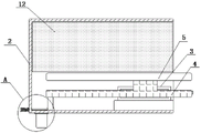
图1为本发明正剖视结构示意图;Fig. 1 is the front cross-sectional structure schematic diagram of the present invention;
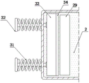
图2为本发明第一置物架正剖视结构示意图;Fig. 2 is a front sectional structural schematic diagram of the first storage rack of the present invention;
图3为本发明基体侧剖视结构示意图;Fig. 3 is a schematic diagram of a side sectional structure of a substrate of the present invention;
图4为本发明空置槽仰视结构示意图;Fig. 4 is a schematic view of the structure of an empty tank according to the present invention;
图5为本发明滑动块正剖视结构示意图;Fig. 5 is a schematic diagram of the front sectional structure of the sliding block of the present invention;
图6为本发明排灰槽俯视结构示意图;Fig. 6 is a schematic diagram of the top view structure of the ash discharge tank of the present invention;
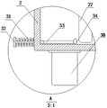
图7为本发明图3中A处放大结构示意图;Figure 7 is a schematic diagram of the enlarged structure at A in Figure 3 of the present invention;
图8为本发明图5中B处放大结构示意图。Fig. 8 is a schematic diagram of the enlarged structure at B in Fig. 5 of the present invention.
图中:1、底座;2、基体;3、第一滑槽;4、滑动块;5、第一置物架;6、第二滑槽;7、第一伸缩弹簧;8、第一滑动杆;9、第二置物架;10、滑动轨道;11、电动伸缩杆;12、保温墙;13、保温室;14、气泵;15、输气管;16、第一气体阀门;17、空置槽;18、固定板;19、防护罩;20、电机;21、负压风机;22、过滤网;23、导气管;24、第二气体阀门;25、拉环;26、牵引绳;27、刮板;28、第二伸缩弹簧;29、排灰槽;30、储灰罐;31、第三伸缩弹簧;32、推杆;33、挡板;34、卡扣。In the figure: 1. base; 2. substrate; 3. first chute; 4. sliding block; 5. first shelf; 6. second chute; 7. first telescopic spring; 8. first sliding rod ;9, the second shelf; 10, sliding track; 11, electric telescopic rod; 12, insulation wall; 13, insulation room; 14, air pump; 15, air pipe; 16, the first gas valve; 18. Fixed plate; 19. Protective cover; 20. Motor; 21. Negative pressure fan; 22. Filter screen; 23. Air guide pipe; 24. Second gas valve; 25. Pull ring; 26. Traction rope; 27.
具体实施方式Detailed ways
下面将结合本发明实施例中的附图,对本发明实施例中的技术方案进行清楚、完整地描述,显然,所描述的实施例仅仅是本发明一部分实施例,而不是全部的实施例。基于本发明中的实施例,本领域普通技术人员在没有做出创造性劳动前提下所获得的所有其他实施例,都属于本发明保护的范围。The following will clearly and completely describe the technical solutions in the embodiments of the present invention with reference to the accompanying drawings in the embodiments of the present invention. Obviously, the described embodiments are only some of the embodiments of the present invention, not all of them. Based on the embodiments of the present invention, all other embodiments obtained by persons of ordinary skill in the art without making creative efforts belong to the protection scope of the present invention.
请参阅图1-8,本发明提供一种技术方案:一种铝箔车间用增容节能退火炉,包括底座1、基体2、第一滑槽3、滑动块4、第一置物架5、第二滑槽6、第一伸缩弹簧7、第一滑动杆8、第二置物架9、滑动轨道10、电动伸缩杆11、保温墙12、保温室13、气泵14、输气管15、第一气体阀门16、空置槽17、固定板18、防护罩19、电机20、负压风机21、过滤网22、导气管23、第二气体阀门24、拉环25、牵引绳26、刮板27、第二伸缩弹簧28、排灰槽29、储灰罐30、第三伸缩弹簧31、推杆32、挡板33和卡扣34。Please refer to Figures 1-8, the present invention provides a technical solution: a capacity-enhancing energy-saving annealing furnace for aluminum foil workshops, including a
底座1上端固定安装有基体2,且基体2内侧开设有第一滑槽3,第一滑槽3内侧嵌套有滑动块4,且滑动块4上端固定安装有第一置物架5,第一置物架5内侧开设有第二滑槽6,且第一置物架5内侧嵌套有第一滑动杆8,并且第一滑动杆8尾端固定连接有第二置物架9,第一置物架5内侧固定安装有第一伸缩弹簧7,且第一伸缩弹簧7尾端固定连接在第二置物架9外侧,基体2内侧固定安装有滑动轨道10,且滑动轨道10内侧嵌套有保温墙12,基体2内侧固定安装有电动伸缩杆11,且电动伸缩杆11输出端固定连接在保温墙12外侧;The upper end of the
根据图1-3所示,滑动块4与第一滑槽3构成滑动结构,且滑动块4正视呈“T”形状结构;第一滑动杆8与第二滑槽6构成滑动结构,且第一滑动杆8尾端第二置物架9通过第一伸缩弹簧7与第一置物架5构成弹性结构;保温墙12关于第一置物架5中点左右对称设置有两组,且保温墙12通过滑动轨道10与基体2构成滑动结构;As shown in Figure 1-3, the sliding
此结构当铝箔材料份量较少时,通过将铝箔材料放置第一置物架5上端,然后推动滑动块4沿着第一滑槽3向基体2内侧移动,滑动块4完全进入基体2内侧后,接通电源,使电动伸缩杆11运行,推动两端的保温墙12沿着滑动轨道10向基体2中点移动,在移动的时候,保温墙12外侧会挤压第二置物架9,从而使第一伸缩弹簧7收缩,第一置物架5通过第一滑动杆8沿着第二滑槽6向第一置物架5内侧移动,使两端的保温墙12不断向基体2内侧移动,减少基体2内侧的空间,基体2内侧空间越小,所消耗的能源越低,可以起到节能的效果,当铝箔分量过多时,反向移动保温墙12,第一伸缩弹簧7通过自身的弹力将第二置物架9弹出,使基体2内侧的容量变大,增加退火的效率,通过此结构,实现了自动调节容量的效果,可根据不同的铝箔分量,调节基体2内侧的容量,达到提高效率、节能的效果。In this structure, when the amount of aluminum foil material is small, by placing the aluminum foil material on the upper end of the
基体2内侧开设有保温室13,且保温室13内侧固定安装有气泵14,气泵14外侧固定连接有输气管15,且输气管15内侧固定安装有第一气体阀门16,并且输气管15尾端固定安装在基体2内侧,基体2内侧开设有空置槽17,且空置槽17内侧固定安装有固定板18,并且固定板18内侧固定安装有过滤网22,固定板18外侧固定安装有防护罩19,且防护罩19内侧固定安装有电机20,电机20输出端贯穿固定板18内侧,且电机20输出端固定安装有负压风机21,空置槽17外侧固定安装有导气管23,且导气管23内侧固定安装有第二气体阀门24,并且导气管23尾端贯穿保温室13内侧,滑动块4外侧设置有拉环25,且拉环25外侧固定连接有牵引绳26,牵引绳26贯穿滑动块4内侧,且牵引绳26尾端固定连接有刮板27,滑动块4内侧固定安装有第二伸缩弹簧28,且第二伸缩弹簧28尾端固定连接在刮板27上端,基体2内侧开设有排灰槽29,且基体2下端固定安装有储灰罐30,基体2外侧固定安装有第三伸缩弹簧31,且第三伸缩弹簧31尾端固定连接在推杆32外侧,推杆32贯穿基体2内侧,且推杆32尾端固定连接有挡板33,挡板33设置在排灰槽29上端,且挡板33尾端固定安装有卡扣34;The inner side of the base body 2 is provided with a heat preservation chamber 13, and an air pump 14 is fixedly installed on the inner side of the heat preservation chamber 13, and an air delivery pipe 15 is fixedly connected to the outside of the air pump 14, and a first gas valve 16 is fixedly installed on the inner side of the air delivery pipe 15, and the tail end of the air delivery pipe 15 Fixedly installed on the inner side of the base body 2, the inner side of the base body 2 is provided with a vacant groove 17, and the inner side of the vacant groove 17 is fixedly installed with a fixed plate 18, and the inner side of the fixed plate 18 is fixedly installed with a filter screen 22, and the outer side of the fixed plate 18 is fixedly installed with a protective cover 19 , and the inner side of the protective cover 19 is fixedly installed with a motor 20, the output end of the motor 20 runs through the inner side of the fixed plate 18, and the output end of the motor 20 is fixedly installed with a negative pressure fan 21, and the outer side of the vacant slot 17 is fixedly installed with an air duct 23, and the air duct 23 The inner side is fixed with a second gas valve 24, and the tail end of the air guide pipe 23 runs through the inner side of the heat preservation chamber 13, and the outer side of the sliding block 4 is provided with a pull ring 25, and the outer side of the pull ring 25 is fixedly connected with a traction rope 26, and the traction rope 26 runs through the sliding block 4, and the tail end of the traction rope 26 is fixedly connected with a scraper 27, the inner side of the sliding block 4 is fixedly installed with a second telescopic spring 28, and the tail end of the second telescopic spring 28 is fixedly connected to the upper end of the scraper 27, and the inner side of the base body 2 is provided with Ash discharge tank 29, and ash storage tank 30 is fixedly installed on the lower end of base body 2, third telescopic spring 31 is fixedly installed on the outside of base body 2, and the tail end of third telescopic spring 31 is fixedly connected to the outside of push rod 32, and push rod 32 runs through the base body 2 inside, and the tail end of the push rod 32 is fixedly connected with a baffle plate 33, the baffle plate 33 is arranged on the upper end of the ash discharge tank 29, and the tail end of the baffle plate 33 is fixedly equipped with a buckle 34;
根据图1、图3-8所示,过滤网22与负压风机21呈前后对应分布,且负压风机21与固定板18构成转动结构;基体2通过导气管23和输气管15与保温室13构成贯通结构;拉环25通过牵引绳26与刮板27构成牵引结构,且刮板27通过第二伸缩弹簧28与滑动块4构成弹性结构;推杆32与基体2构成滑动结构,且推杆32通过第三伸缩弹簧31与基体2构成弹性结构;挡板33与排灰槽29呈上下对应分布,且挡板33外侧卡扣34与刮板27呈左右对称分布;As shown in Fig. 1 and Fig. 3-8, the
此结构当对铝箔材料退火完毕后,打开第二气体阀门24,运行电机20,电机20运行会通过输出端带动负压风机21转动,将基体2内侧的热量抽离,过滤网22可以对基体2内侧的灰渣进行过滤,热量通过导气管23输送至保温室13中保存,当需要对下一批的铝箔材质进行退火处理时,打开第一气体阀门16,通过运行气泵14,使气泵14通过输气管15将热量输送至基体2内侧,进行重复使用,使基体2内侧保持一个基本的热量,减少能源的消耗,通过此结构,从而实现了节能的效果,可以对退火炉中的热量进行重复利用,最大程度的减少能源的消耗,且在对第二批次铝箔进行退火时,在推动滑动块4向前移动的时候,滑动块 4下端的刮板27会推动退火炉底部的灰渣向前移动聚集,当刮板27外侧触碰到卡扣34时,会通过卡扣34推动挡板33向基体2侧端移动,从而使排灰槽29处于开口状态,退火产生的灰渣通过排灰槽29进入储灰罐30中,清理完毕后,通过拉动拉环25,通过牵引绳26对刮板27产生牵引力,使刮板27向上移动,卡扣34失去刮板27的挤压后,通过第三伸缩弹簧31的弹力,使挡板33复位,对排灰槽29进行密封,防止设备整体的密封性不足,通过此结构,实现了对灰渣的自动清理,节约了人力。In this structure, after the annealing of the aluminum foil material is completed, the
在本发明的描述中,除非另有说明,“多个”的含义是两个或两个以上;术语“上”、“下”、“左”、“右”、“内”、“外”、“前端”、“后端”、“头部”、“尾部”等指示的方位或位置关系为基于附图所示的方位或位置关系,仅是为了便于描述本发明和简化描述,而不是指示或暗示所指的装置或元件必须具有特定的方位、以特定的方位构造和操作,因此不能理解为对本发明的限制。此外,术语“第一”、“第二”、“第三”等仅用于描述目的,而不能理解为指示或暗示相对重要性。In the description of the present invention, unless otherwise stated, the meaning of "plurality" is two or more; the terms "upper", "lower", "left", "right", "inner", "outer" , "front end", "rear end", "head", "tail", etc. indicate the orientation or positional relationship based on the orientation or positional relationship shown in the drawings, and are only for the convenience of describing the present invention and simplifying the description, rather than Nothing indicating or implying that a referenced device or element must have a particular orientation, be constructed, and operate in a particular orientation should therefore not be construed as limiting the invention. In addition, the terms "first", "second", "third", etc. are used for descriptive purposes only and should not be construed as indicating or implying relative importance.
在本发明的描述中,需要说明的是,除非另有明确的规定和限定,术语“相连”、“连接”应做广义理解,例如,可以是固定连接,也可以是可拆卸连接,或一体地连接;可以是机械连接,也可以是电连接;可以是直接相连,也可以通过中间媒介间接相连。对于本领域的普通技术人员而言,可以具体情况理解上述术语在本发明中的具体含义。In the description of the present invention, it should be noted that unless otherwise specified and limited, the terms "connected" and "connected" should be understood in a broad sense, for example, it can be a fixed connection, a detachable connection, or an integral Ground connection; it can be mechanical connection or electrical connection; it can be direct connection or indirect connection through an intermediary. Those of ordinary skill in the art can understand the specific meanings of the above terms in the present invention in specific situations.
尽管参照前述实施例对本发明进行了详细的说明,对于本领域的技术人员来说,其依然可以对前述各实施例所记载的技术方案进行修改,或者对其中部分技术特征进行等同替换,凡在本发明的精神和原则之内,所作的任何修改、等同替换、改进等,均应包含在本发明的保护范围之内。Although the present invention has been described in detail with reference to the aforementioned embodiments, those skilled in the art can still modify the technical solutions described in the aforementioned embodiments, or perform equivalent replacements for some of the technical features. Within the spirit and principles of the present invention, any modifications, equivalent replacements, improvements, etc., shall be included in the protection scope of the present invention.
Claims (10)
Priority Applications (1)
| Application Number | Priority Date | Filing Date | Title |
|---|---|---|---|
| CN202211554215.9A CN115627341A (en) | 2022-12-06 | 2022-12-06 | Capacity-increasing energy-saving annealing furnace for aluminum foil workshop |
Applications Claiming Priority (1)
| Application Number | Priority Date | Filing Date | Title |
|---|---|---|---|
| CN202211554215.9A CN115627341A (en) | 2022-12-06 | 2022-12-06 | Capacity-increasing energy-saving annealing furnace for aluminum foil workshop |
Publications (1)
| Publication Number | Publication Date |
|---|---|
| CN115627341A true CN115627341A (en) | 2023-01-20 |
Family
ID=84909913
Family Applications (1)
| Application Number | Title | Priority Date | Filing Date |
|---|---|---|---|
| CN202211554215.9A Pending CN115627341A (en) | 2022-12-06 | 2022-12-06 | Capacity-increasing energy-saving annealing furnace for aluminum foil workshop |
Country Status (1)
| Country | Link |
|---|---|
| CN (1) | CN115627341A (en) |
Cited By (1)
| Publication number | Priority date | Publication date | Assignee | Title |
|---|---|---|---|---|
| CN121220299A (en) * | 2025-10-09 | 2025-12-30 | 安徽艾芝园农业科技有限公司 | A smart mugwort seedling rack |
Citations (6)
| Publication number | Priority date | Publication date | Assignee | Title |
|---|---|---|---|---|
| CN210764402U (en) * | 2019-09-18 | 2020-06-16 | 青岛明朗环境工程有限公司 | Sludge discharge device for sewage treatment |
| CN215481107U (en) * | 2021-06-02 | 2022-01-11 | 福建鼎信科技有限公司 | Energy-saving annealing furnace |
| CN216457303U (en) * | 2021-12-21 | 2022-05-10 | 江苏荆溪环保设备有限公司 | Sewage treatment prevents stifled mud discharging equipment |
| CN217418222U (en) * | 2022-04-01 | 2022-09-13 | 贝卡特环境技术(北京)有限公司 | Sludge discharge device for sewage treatment |
| CN115369227A (en) * | 2022-09-19 | 2022-11-22 | 绍兴艾笛薇机械设备有限公司 | High-efficient heated air circulation guiding device for heat treatment furnace |
| CN217895713U (en) * | 2022-08-05 | 2022-11-25 | 深圳市明鑫工业材料有限公司 | Heat treatment device for conductive copper strip production |
-
2022
- 2022-12-06 CN CN202211554215.9A patent/CN115627341A/en active Pending
Patent Citations (6)
| Publication number | Priority date | Publication date | Assignee | Title |
|---|---|---|---|---|
| CN210764402U (en) * | 2019-09-18 | 2020-06-16 | 青岛明朗环境工程有限公司 | Sludge discharge device for sewage treatment |
| CN215481107U (en) * | 2021-06-02 | 2022-01-11 | 福建鼎信科技有限公司 | Energy-saving annealing furnace |
| CN216457303U (en) * | 2021-12-21 | 2022-05-10 | 江苏荆溪环保设备有限公司 | Sewage treatment prevents stifled mud discharging equipment |
| CN217418222U (en) * | 2022-04-01 | 2022-09-13 | 贝卡特环境技术(北京)有限公司 | Sludge discharge device for sewage treatment |
| CN217895713U (en) * | 2022-08-05 | 2022-11-25 | 深圳市明鑫工业材料有限公司 | Heat treatment device for conductive copper strip production |
| CN115369227A (en) * | 2022-09-19 | 2022-11-22 | 绍兴艾笛薇机械设备有限公司 | High-efficient heated air circulation guiding device for heat treatment furnace |
Cited By (1)
| Publication number | Priority date | Publication date | Assignee | Title |
|---|---|---|---|---|
| CN121220299A (en) * | 2025-10-09 | 2025-12-30 | 安徽艾芝园农业科技有限公司 | A smart mugwort seedling rack |
Similar Documents
| Publication | Publication Date | Title |
|---|---|---|
| CN207525319U (en) | A kind of titanium alloy sheet band processing annealing furnace | |
| CN113381326A (en) | Electrical engineering is with high-efficient heat dissipation electric appliance cabinet | |
| CN112134163A (en) | A waterproof heat dissipation power cabinet suitable for outdoor | |
| CN218566187U (en) | Environment-friendly energy-saving cooling device for sintering hollow bricks | |
| CN216048822U (en) | Degreasing and drying equipment for fin heat exchanger | |
| CN207305251U (en) | A kind of frequency-conversion control cabinet heat dissipation tank | |
| CN114060983B (en) | Internet of things-based cooling system for machine room monitoring and cooling method thereof | |
| CN216845110U (en) | Energy-saving cold-storage type heat exchange device for central air conditioner | |
| CN213866302U (en) | Energy-saving aluminum profile annealing furnace | |
| CN115915681B (en) | Dustproof heat dissipation rack | |
| CN212362833U (en) | Aluminum bar homogenizing furnace | |
| CN108588382A (en) | A kind of mixed type brass tube annealing furnace | |
| CN114823331A (en) | Nitrogen-hydrogen annealing equipment for manufacturing triode device and process thereof | |
| CN218673111U (en) | Vacuum-pumping device for vacuum microwave smelting furnace | |
| CN223024807U (en) | Energy-saving control device of high-voltage frequency converter | |
| CN218270182U (en) | A box-type atmosphere furnace | |
| CN217004962U (en) | Vortex tube cooling device for electric control system | |
| CN219412856U (en) | Heat preservation and energy saving device utilizing waste heat of air compressor | |
| CN219415054U (en) | Radiation air conditioner end device integrated in ceiling board | |
| CN112218498A (en) | High-efficient cooling system based on computer lab rotating ring detects cabinet | |
| CN220524652U (en) | Energy-saving electric heating equipment | |
| CN222257599U (en) | A sintering device for processing shale porous bricks | |
| CN210718639U (en) | Cooling structure for roasting graphite electrode | |
| CN222007911U (en) | High-pressure heat treatment equipment for powder metallurgy products | |
| CN210641217U (en) | Static phase advancer cooling device |
Legal Events
| Date | Code | Title | Description |
|---|---|---|---|
| PB01 | Publication | ||
| PB01 | Publication | ||
| SE01 | Entry into force of request for substantive examination | ||
| SE01 | Entry into force of request for substantive examination | ||
| RJ01 | Rejection of invention patent application after publication | ||
| RJ01 | Rejection of invention patent application after publication |
Application publication date: 20230120 |