CN115609840A - A rubber molding injection machine for auto parts - Google Patents
A rubber molding injection machine for auto parts Download PDFInfo
- Publication number
- CN115609840A CN115609840A CN202211303959.3A CN202211303959A CN115609840A CN 115609840 A CN115609840 A CN 115609840A CN 202211303959 A CN202211303959 A CN 202211303959A CN 115609840 A CN115609840 A CN 115609840A
- Authority
- CN
- China
- Prior art keywords
- rubber
- plate
- upper portion
- mould
- die
- Prior art date
- Legal status (The legal status is an assumption and is not a legal conclusion. Google has not performed a legal analysis and makes no representation as to the accuracy of the status listed.)
- Withdrawn
Links
Images


Classifications
-
- B—PERFORMING OPERATIONS; TRANSPORTING
- B29—WORKING OF PLASTICS; WORKING OF SUBSTANCES IN A PLASTIC STATE IN GENERAL
- B29C—SHAPING OR JOINING OF PLASTICS; SHAPING OF MATERIAL IN A PLASTIC STATE, NOT OTHERWISE PROVIDED FOR; AFTER-TREATMENT OF THE SHAPED PRODUCTS, e.g. REPAIRING
- B29C45/00—Injection moulding, i.e. forcing the required volume of moulding material through a nozzle into a closed mould; Apparatus therefor
- B29C45/03—Injection moulding apparatus
-
- B—PERFORMING OPERATIONS; TRANSPORTING
- B29—WORKING OF PLASTICS; WORKING OF SUBSTANCES IN A PLASTIC STATE IN GENERAL
- B29C—SHAPING OR JOINING OF PLASTICS; SHAPING OF MATERIAL IN A PLASTIC STATE, NOT OTHERWISE PROVIDED FOR; AFTER-TREATMENT OF THE SHAPED PRODUCTS, e.g. REPAIRING
- B29C45/00—Injection moulding, i.e. forcing the required volume of moulding material through a nozzle into a closed mould; Apparatus therefor
- B29C45/17—Component parts, details or accessories; Auxiliary operations
-
- B—PERFORMING OPERATIONS; TRANSPORTING
- B29—WORKING OF PLASTICS; WORKING OF SUBSTANCES IN A PLASTIC STATE IN GENERAL
- B29C—SHAPING OR JOINING OF PLASTICS; SHAPING OF MATERIAL IN A PLASTIC STATE, NOT OTHERWISE PROVIDED FOR; AFTER-TREATMENT OF THE SHAPED PRODUCTS, e.g. REPAIRING
- B29C45/00—Injection moulding, i.e. forcing the required volume of moulding material through a nozzle into a closed mould; Apparatus therefor
- B29C45/17—Component parts, details or accessories; Auxiliary operations
- B29C45/1756—Handling of moulds or mould parts, e.g. mould exchanging means
-
- B—PERFORMING OPERATIONS; TRANSPORTING
- B29—WORKING OF PLASTICS; WORKING OF SUBSTANCES IN A PLASTIC STATE IN GENERAL
- B29C—SHAPING OR JOINING OF PLASTICS; SHAPING OF MATERIAL IN A PLASTIC STATE, NOT OTHERWISE PROVIDED FOR; AFTER-TREATMENT OF THE SHAPED PRODUCTS, e.g. REPAIRING
- B29C45/00—Injection moulding, i.e. forcing the required volume of moulding material through a nozzle into a closed mould; Apparatus therefor
- B29C45/17—Component parts, details or accessories; Auxiliary operations
- B29C45/26—Moulds
-
- B—PERFORMING OPERATIONS; TRANSPORTING
- B29—WORKING OF PLASTICS; WORKING OF SUBSTANCES IN A PLASTIC STATE IN GENERAL
- B29C—SHAPING OR JOINING OF PLASTICS; SHAPING OF MATERIAL IN A PLASTIC STATE, NOT OTHERWISE PROVIDED FOR; AFTER-TREATMENT OF THE SHAPED PRODUCTS, e.g. REPAIRING
- B29C45/00—Injection moulding, i.e. forcing the required volume of moulding material through a nozzle into a closed mould; Apparatus therefor
- B29C45/17—Component parts, details or accessories; Auxiliary operations
- B29C45/72—Heating or cooling
- B29C45/73—Heating or cooling of the mould
-
- B—PERFORMING OPERATIONS; TRANSPORTING
- B29—WORKING OF PLASTICS; WORKING OF SUBSTANCES IN A PLASTIC STATE IN GENERAL
- B29C—SHAPING OR JOINING OF PLASTICS; SHAPING OF MATERIAL IN A PLASTIC STATE, NOT OTHERWISE PROVIDED FOR; AFTER-TREATMENT OF THE SHAPED PRODUCTS, e.g. REPAIRING
- B29C45/00—Injection moulding, i.e. forcing the required volume of moulding material through a nozzle into a closed mould; Apparatus therefor
- B29C45/17—Component parts, details or accessories; Auxiliary operations
- B29C2045/1784—Component parts, details or accessories not otherwise provided for; Auxiliary operations not otherwise provided for
-
- B—PERFORMING OPERATIONS; TRANSPORTING
- B29—WORKING OF PLASTICS; WORKING OF SUBSTANCES IN A PLASTIC STATE IN GENERAL
- B29L—INDEXING SCHEME ASSOCIATED WITH SUBCLASS B29C, RELATING TO PARTICULAR ARTICLES
- B29L2031/00—Other particular articles
- B29L2031/30—Vehicles, e.g. ships or aircraft, or body parts thereof
Landscapes
- Engineering & Computer Science (AREA)
- Manufacturing & Machinery (AREA)
- Mechanical Engineering (AREA)
- Injection Moulding Of Plastics Or The Like (AREA)
Abstract
本发明涉及汽车零件生产设备技术领域,且公开了一种汽车零件用橡胶成型注射机,包括加工桌面,所述加工桌面上部的内侧开设有滑轨,所述滑轨的上部活动套接有下模限定座,所述加工桌面的外侧固定连接有支撑座,所述支撑座的内部安装有第一螺纹杆,所述第一螺纹杆的内侧螺纹连接有上模,所述上模上部的一侧固定连接有第二螺纹柱。该汽车零件用橡胶成型注射机,通过上模的上部安装有预热板,将橡胶放置在预热板的内部,同时预热板对上模加工产生的余热进行吸收,同时预热板对上部放置的橡胶进行预热处理,且橡胶限定杆插入橡胶两端的内部,橡胶限定杆对橡胶的位置进行限定,避免橡胶预热取出时拿取处出现烫伤的问题。

The invention relates to the technical field of auto parts production equipment, and discloses a rubber molding injection machine for auto parts, which includes a processing table top, a slide rail is provided on the inner side of the upper part of the processing table top, and a lower A mold limiting seat, the outer side of the processing table is fixedly connected with a support seat, the inside of the support seat is installed with a first threaded rod, the inner side of the first threaded rod is threaded with an upper die, and one of the upper parts of the upper die The side is fixedly connected with a second threaded post. The rubber molding injection machine for auto parts is equipped with a preheating plate on the upper part of the upper mold, and the rubber is placed inside the preheating plate. At the same time, the preheating plate absorbs the waste heat generated by the upper mold processing. The placed rubber is preheated, and the rubber limiting rod is inserted into the interior of both ends of the rubber. The rubber limiting rod limits the position of the rubber to avoid scalding when the rubber is preheated and taken out.
Description
技术领域technical field
本发明涉及汽车零件生产设备技术领域,具体为一种汽车零件用橡胶成型注射机。The invention relates to the technical field of auto parts production equipment, in particular to a rubber molding injection machine for auto parts.
背景技术Background technique
在汽车进行生产时,需要采用橡胶零件进行拼装,在汽车零件进行生产时,采用注射机推动橡胶注入模型的内部成型,为了增加汽车零件生产时的便捷性,研发出一种汽车零件用橡胶成型注射机。In the production of automobiles, it is necessary to use rubber parts for assembly. In the production of automobile parts, an injection machine is used to drive the internal molding of the rubber injection model. In order to increase the convenience of the production of automobile parts, a rubber molding for automobile parts has been developed. injection machine.
在现有的汽车零件用橡胶成型注射机中,在汽车零件进行生产时,需要利用橡胶注塑成型的方式进行生产汽车零件,汽车零件生产时需要注射机在带动橡胶注入模型的内部时,橡胶呈块状,为了方便携带橡胶成型,需要在橡胶加入注射机的内部前,将橡胶放置在预热箱的内部,预热箱携带橡胶预热软化,但安装预热箱并驱动预热箱带动橡胶软化过程中,预热箱加热会产生能量,产生能力会造成浪费资源的问题;同时注射机带动软化的橡胶注入模型的内部时,为了增加模具成型的效率性,需要利用注射机推动橡胶同步注入不同模具的内部,橡胶同步注入不同模具的内部需要在模具内部开设多向流通的注塑管道,橡胶流通时会填充在橡胶流通管道的内部,同时橡胶流通管道开设在上模板的内部,管道在上模板的内部后会导致橡胶停止注塑时,橡胶会堆积在橡胶流通管道的内部,同时注塑设备停止加工,注塑设备冷却会导致内部填充的橡胶冷却凝固后会卡死在管道的内部,而卡死的橡胶管道会影响下次注塑操作。In the existing rubber molding injection machines for auto parts, it is necessary to use rubber injection molding to produce auto parts when producing auto parts. In block shape, in order to facilitate the molding of rubber, it is necessary to place the rubber inside the preheating box before adding the rubber into the injection machine. The preheating box carries the rubber to preheat and soften, but install the preheating box and drive the preheating box to drive the rubber During the softening process, the heating of the preheating box will generate energy, and the generation capacity will cause a waste of resources; at the same time, when the injection machine drives the softened rubber into the mold, in order to increase the efficiency of mold molding, it is necessary to use the injection machine to push the rubber into synchronously. In the interior of different molds, rubber is injected into the interior of different molds synchronously. It is necessary to set up multi-directional circulation injection pipes inside the mold. When the rubber circulates, it will be filled in the interior of the rubber circulation pipe. The inside of the template will cause the rubber to stop injection molding, the rubber will accumulate inside the rubber circulation pipe, and the injection molding equipment will stop processing at the same time. The cooling of the injection molding equipment will cause the rubber filled inside to be stuck inside the pipe after cooling and solidification, and it will be stuck. The rubber pipes that have been removed will affect the next injection molding operation.
发明内容Contents of the invention
针对现有汽车零件用橡胶成型注射机的不足,本发明提供了一种汽车零件用橡胶成型注射机,具备将预热板安装在上模的上部,同时橡胶放置在预热板的上部,预热板携带上模加工产生的热量进行吸收,同时利用上模的余热对预热板内部夹持的橡胶进行预热处理,增加能源的利用率,同时橡胶限定杆插入橡胶的内部,在对橡胶拿取时,避免直接拿取导致高温对工作人员造成烫伤的优点,解决了上述背景技术中提出的问题。Aiming at the deficiencies of existing rubber molding injection machines for auto parts, the present invention provides a rubber molding injection machine for auto parts. The hot plate carries the heat generated by the upper mold processing to absorb, and at the same time uses the waste heat of the upper mold to preheat the rubber clamped inside the preheating plate to increase the utilization rate of energy. When taking it, it avoids the advantage of directly taking it and causing high temperature to cause burns to the staff, and solves the problems raised in the above-mentioned background technology.
本发明提供如下技术方案:一种汽车零件用橡胶成型注射机,包括加工桌面,所述加工桌面上部的内侧开设有滑轨,所述滑轨的上部活动套接有下模限定座,所述加工桌面的外侧固定连接有支撑座,所述支撑座的内部安装有第一螺纹杆,所述第一螺纹杆的内侧螺纹连接有上模,所述上模上部的一侧固定连接有第二螺纹柱,所述第二螺纹柱的外部活动套接有第一连接板,所述第一连接板的内侧固定连接有注射管道,所述注射管道上部的外侧固定连接有橡胶入料管道,所述注射管道的内部活动套接有螺旋输送管,所述下模限定座的上部活动套接有下模,所述下模上部的外侧固定连接有凹槽外限定板,所述下模上部一侧的内侧固定连接有压模形状凹槽,所述上模内部的一侧活动套接有拼接滑轨,所述拼接滑轨的内侧固定连接有上模成型板,所述上模成型板的上部开设有注胶孔,所述上模的上部固定连接有预热板,所述预热板上部的一侧活动套接有防护板,所述预热板一侧内部活动套接有橡胶限定杆。The present invention provides the following technical solutions: a rubber molding injection machine for auto parts, including a processing table top, a slide rail is arranged on the inner side of the upper part of the processing table top, and a lower mold limiting seat is movably socketed on the upper part of the slide rail, and the The outer side of the processing desktop is fixedly connected with a support seat, the inside of the support seat is installed with a first threaded rod, the inner side of the first threaded rod is threaded with an upper die, and one side of the upper part of the upper die is fixedly connected with a second threaded rod. A threaded column, the outer part of the second threaded column is movably connected with a first connecting plate, the inner side of the first connecting plate is fixedly connected with an injection pipeline, and the outer side of the upper part of the injection pipeline is fixedly connected with a rubber feeding pipeline, so The inside of the injection pipeline is movably socketed with a spiral conveying pipe, the upper part of the lower mold limiting seat is movably socketed with a lower mold, and the outer side of the upper part of the lower mold is fixedly connected with a groove outer limiting plate, and the upper part of the lower mold is a The inner side of the side is fixedly connected with a die-shaped groove, and one side of the upper mold is movably sleeved with a splicing slide rail, and the inner side of the splicing slide rail is fixedly connected with an upper mold forming plate, and the upper mold forming plate The upper part is provided with a glue injection hole, the upper part of the upper mold is fixedly connected with a preheating plate, one side of the upper part of the preheating plate is movably socketed with a protective plate, and one side of the preheating plate is movably socketed with a rubber limiter. pole.
优选的,所述下模限定座的下部开设有滑槽杆,所述滑槽杆活动套接在滑轨的内部。Preferably, a chute rod is provided at the lower part of the limiting seat of the lower mold, and the chute rod is movably socketed inside the slide rail.
优选的,所述上模的两侧安装有连接板,所述连接板与第一螺纹杆之间相互螺纹连接,所述第一螺纹杆的下部安装有电机。Preferably, connecting plates are installed on both sides of the upper die, and the connecting plate and the first threaded rod are screwed to each other, and a motor is installed on the lower part of the first threaded rod.
优选的,所述下模限定座与下模之间相互套接限定,所述下模限定座和下模连接处之间安装有紧固螺栓。Preferably, the lower mold limiting seat and the lower mold are mutually socketed and defined, and fastening bolts are installed between the lower mold limiting seat and the joint of the lower mold.
优选的,所述下模活动套接在上模的内侧,所述压模形状凹槽和上模成型板之间开设有注胶凹槽,所述凹槽外限定板的上部紧贴上模成型板的内壁。Preferably, the lower mold is movably socketed on the inner side of the upper mold, and a glue injection groove is opened between the shape groove of the press mold and the molding plate of the upper mold, and the upper part of the outer limiting plate of the groove is close to the upper mold The inner wall of the forming board.
优选的,所述拼接滑轨呈L形,所述拼接滑轨活动套接在上模的内部,所述拼接滑轨的上部与上模之间含有活动槽,所述注胶孔活动槽和注射管道的下部相互连通。Preferably, the splicing slide rail is L-shaped, and the splicing slide rail is movably socketed inside the upper mold, and there is a movable groove between the upper part of the splicing slide rail and the upper mold, and the movable groove of the injection hole and The lower parts of the injection pipes communicate with each other.
优选的,所述预热板的外部安装有挡板,所述防护板覆盖在橡胶限定杆的外部,所述预热板的上部摆放有橡胶,所述橡胶限定杆插入橡胶的内部。Preferably, a baffle is installed on the outside of the preheating plate, the protective plate covers the outside of the rubber limiting rod, rubber is placed on the upper part of the preheating plate, and the rubber limiting rod is inserted into the rubber.
优选的,所述注射管道的下部延伸至上模上部的中部,所述第二螺纹柱的外侧安装有螺帽,所述螺旋输送管的外部安装有螺旋叶片,螺旋叶片紧贴注射管道的内壁。Preferably, the lower part of the injection pipe extends to the middle part of the upper mold, the outer side of the second threaded column is installed with a nut, the outer part of the spiral delivery pipe is installed with a helical blade, and the helical blade is close to the inner wall of the injection pipe.
与现有汽车零件用橡胶成型注射机对比,本发明具备以下有益效果:Compared with the existing rubber molding injection machine for auto parts, the present invention has the following beneficial effects:
1、该汽车零件用橡胶成型注射机,通过上模成型板经过拼接滑轨限定在上模和内部,同时下模活动套接在下模限定座的上端,至此装置下模和上模成型板可进行拆卸替换,在对汽车不同零件进行加工时,方便对模具进行替换的作用。1. The rubber molding injection machine used for auto parts is limited to the upper mold and the inside by the upper mold forming plate through splicing slide rails, and the lower mold is movably connected to the upper end of the lower mold limiting seat. It can be disassembled and replaced, and it is convenient to replace the mold when processing different parts of the car.
2、该汽车零件用橡胶成型注射机,通过上模的上部安装有预热板,将橡胶放置在预热板的内部,同时预热板对上模加工产生的余热进行吸收,同时预热板对上部放置的橡胶进行预热处理,且橡胶限定杆插入橡胶两端的内部,橡胶限定杆对橡胶的位置进行限定,避免橡胶预热取出时拿取处出现烫伤的问题。2. The rubber molding injection machine for auto parts has a preheating plate installed on the upper part of the upper mold, and the rubber is placed inside the preheating plate. At the same time, the preheating plate absorbs the waste heat generated by the upper mold processing, and the preheating plate The rubber placed on the upper part is preheated, and the rubber limiting rod is inserted into the interior of both ends of the rubber. The rubber limiting rod limits the position of the rubber to avoid scalding when the rubber is preheated and taken out.
3、该汽车零件用橡胶成型注射机,通过上模成型板和上模的内部形成凹槽,并注射管道带动橡胶注入上模的内部,橡胶均匀地填充至上模成型板和上模之间,同时经过上模成型板外部开设的注胶孔,注胶孔可依次均匀的携带橡胶填充至压模形状凹槽和上模成型板之间,增加橡胶填充时增加灵活性,同时上模成型板可从上模的内部拆卸,在对上模成型板和上模之间注胶产生的杂质可快速清理的作用。3. The rubber molding injection machine for auto parts forms grooves through the molding plate of the upper mold and the inside of the upper mold, and the injection pipe drives the rubber into the inside of the upper mold, and the rubber is evenly filled between the molding plate and the upper mold. At the same time, through the injection holes opened outside the molding plate of the upper mold, the injection holes can evenly carry rubber to fill between the shape groove of the die and the molding plate of the upper mold in sequence, increasing the flexibility when filling the rubber, and at the same time the molding plate of the upper mold It can be disassembled from the inside of the upper mold, and can quickly clean up the impurities generated by the glue injection between the upper mold forming plate and the upper mold.
附图说明Description of drawings
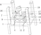
图1为本发明主体结构示意图;Fig. 1 is a schematic diagram of the main structure of the present invention;
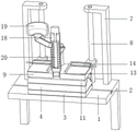
图2为本发明主体正视剖面结构示意图;Fig. 2 is a schematic diagram of a front view sectional structure of the main body of the present invention;
图3为本发明主体侧视剖面结构示意图;Fig. 3 is a schematic diagram of a side view sectional structure of the main body of the present invention;
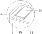
图4为本发明A处放大结构示意图;Fig. 4 is the schematic diagram of enlarged structure of place A of the present invention;
图5为本发明B处放大结构示意图。Fig. 5 is a schematic diagram of the enlarged structure at B of the present invention.
图中:1、加工桌面;2、滑轨;3、下模限定座;4、下模;5、凹槽外限定板;6、压模形状凹槽;7、支撑座;8、第一螺纹杆;9、上模;10、拼接滑轨;11、上模成型板;12、注胶孔;13、预热板;14、防护板;15、橡胶限定杆;16、第二螺纹柱;17、第一连接板;18、注射管道;19、橡胶入料管道;20、螺旋输送管。In the figure: 1. Processing table top; 2. Slide rail; 3. Lower mold limiting seat; 4. Lower mold; 5. Outer groove limiting plate; 6. Die shape groove; Threaded rod; 9. Upper mold; 10. Splicing slide rail; 11. Forming plate of upper mold; 12. Glue injection hole; 13. Preheating plate; 14. Protective plate; 15. Rubber limiting rod; 16. Second threaded column ; 17, the first connecting plate; 18, the injection pipe; 19, the rubber feeding pipe; 20, the screw conveying pipe.
具体实施方式detailed description
下面将结合本发明实施例中的附图,对本发明实施例中的技术方案进行清楚、完整地描述,显然,所描述的实施例仅仅是本发明一部分实施例,而不是全部的实施例。基于本发明中的实施例,本领域普通技术人员在没有做出创造性劳动前提下所获得的所有其他实施例,都属于本发明保护的范围。The following will clearly and completely describe the technical solutions in the embodiments of the present invention with reference to the accompanying drawings in the embodiments of the present invention. Obviously, the described embodiments are only some of the embodiments of the present invention, not all of them. Based on the embodiments of the present invention, all other embodiments obtained by persons of ordinary skill in the art without making creative efforts belong to the protection scope of the present invention.
请参阅图1、图2、图3、图4和图5,一种汽车零件用橡胶成型注射机,包括加工桌面1,加工桌面1上部的内侧开设有滑轨2,滑轨2对下模限定座3移动时提供活动区间,滑轨2的上部活动套接有下模限定座3,下模限定座3对下模4的位置进行支撑,加工桌面1的外侧固定连接有支撑座7,支撑座7带动第一螺纹杆8的位置进行限定,支撑座7的内部安装有第一螺纹杆8,第一螺纹杆8携带上模9向上移动提供动力,第一螺纹杆8的内侧螺纹连接有上模9,上模9带动上模成型板11的位置进行限定,上模9上部的一侧固定连接有第二螺纹柱16,第二螺纹柱16的外部活动套接有第一连接板17,第二螺纹柱16带动第一连接板17的位置进行限定,同时携带注射管道18与上模9之间的位置进行限定,第一连接板17的内侧固定连接有注射管道18,注射管道18上部的外侧固定连接有橡胶入料管道19,橡胶入料管道19带动橡胶填充至注射管道18的内部,注射管道18的内部活动套接有螺旋输送管20,螺旋输送管20产生螺旋力,并推动橡胶注入注射管道18的下部,下模限定座3的上部活动套接有下模4,下模4上部的外侧固定连接有凹槽外限定板5,凹槽外限定板5对成型凹槽的外侧进行密封,下模4上部一侧的内侧固定连接有压模形状凹槽6,压模形状凹槽6带动成型零件的下部进行限定,上模9内部的一侧活动套接有拼接滑轨10,拼接滑轨10带动上模成型板11在上模9的内部可进行拆卸限定,拼接滑轨10的内侧固定连接有上模成型板11,上模成型板11的上部开设有注胶孔12,注胶孔12带动橡胶填充至压模形状凹槽6和上模成型板11之间提供活动区间,上模9的上部固定连接有预热板13,预热板13带动橡胶进行预热,预热板13上部的一侧活动套接有防护板14,预热板13一侧内部活动套接有橡胶限定杆15,橡胶限定杆15带动橡胶进行限定,并方便带动预热后的橡胶进行拿取。Please refer to Fig. 1, Fig. 2, Fig. 3, Fig. 4 and Fig. 5, a rubber molding injection machine for auto parts, including a processing table 1, and a
参考图1,下模限定座3的下部开设有滑槽杆,滑槽杆活动套接在滑轨2的内部,通过加工桌面1的上部开设有滑轨2,并下模限定座3下部安装的滑槽杆活动套接在滑轨2的内部,下模限定座3在加工桌面1的上部存在活动区间,同时调节下模限定座3移动至加工桌面1上部的前端后,并可在对橡胶成型后,方便携带汽车零件取出,同时携带下模限定座3在加工桌面1的上部移动时增加稳定性。Referring to Fig. 1, the lower part of the lower
参考图1,上模9的两侧安装有连接板,连接板与第一螺纹杆8之间相互螺纹连接,第一螺纹杆8的下部安装有电机,通过将上模9的外侧安装有连接板,并带动连接板与第一螺纹杆8之间相互螺纹连接,通过启动第一螺纹杆8向安装电机,电机带动第一螺纹杆8转动,第一螺纹杆8带动上模9的高度进行调节,至此带动下模4与上模9之间进行合模时提供动力的作用。With reference to Fig. 1, connecting plate is installed on the both sides of
参考图1,下模限定座3与下模4之间相互套接限定,下模限定座3和下模4连接处之间安装有紧固螺栓,通过将下模限定座3和下模4之间相互套接限定,并下模4可从下模限定座3的上部进行拆卸,在对不同型号的零件进行生产时,方便带动下模4进行替换和拆卸的作用,且将下模限定座3和下模4之间安装有紧固螺栓,紧固螺栓可携带下模限定座3和下模4之间进行安装时增加稳固性。Referring to Fig. 1, the lower
参考图5,下模4活动套接在上模9的内侧,压模形状凹槽6和上模成型板11之间开设有注胶凹槽,凹槽外限定板5的上部紧贴上模成型板11的内壁,通过下模4与上模9之间进行重合后,压模形状凹槽6和上模成型板11之间形成注胶凹槽,同时将胶料填充至凹槽的内部后,可形成待生产零件的形状,同时凹槽外限定板5的上部紧贴上模成型板11的内壁,凹槽外限定板5可对成型零件的外侧进行防护的作用。Referring to Fig. 5, the
参考图5,拼接滑轨10呈L形,拼接滑轨10活动套接在上模9的内部,拼接滑轨10的上部与上模9之间含有活动槽,注胶孔12活动槽和注射管道18的下部相互连通,通过拼接滑轨10呈L形,同时将上模成型板11安装在上模9的内侧时,可携带拼接滑轨10活动套接在内部,即上模成型板11安装在上模9的内侧时可保持稳定性。Referring to Fig. 5, the
参考图1和图4,预热板13的外部安装有挡板,防护板14覆盖在橡胶限定杆15的外部,预热板13的上部摆放有橡胶,橡胶限定杆15插入橡胶的内部,通过预热板13安装在上模9的上部,并上模9在进行注胶过程中,可携带橡胶放置在预热板13的上部,同时经过上模9加工过程中产生的余热对橡胶进行预热处理,同时预热板13对橡胶预热提供限定区间,且将橡胶的两侧插入有橡胶限定杆15,且转动防护板14,防护板14对橡胶限定杆15的位置进行限定,同时橡胶限定杆15可带动预热后的橡胶取出,避免手动直接拿取橡胶导致烫伤的问题。Referring to Figure 1 and Figure 4, a baffle is installed on the outside of the preheating
参考图3,注射管道18的下部延伸至上模9上部的中部,第二螺纹柱16的外侧安装有螺帽,螺旋输送管20的外部安装有螺旋叶片,螺旋叶片紧贴注射管道18的内壁,通过转动第二螺纹柱16外侧安装的螺帽,第二螺纹柱16对注射管道18和上模9之间的位置进行限定,同时将橡胶放置在橡胶入料管道19的内部,并启动螺旋输送管20上部安装的电机,电机带动螺旋扇叶转动,螺旋扇叶携带橡胶箱内侧挤压,同时将挤压后的橡胶向下传输,同时橡胶经过橡胶入料管道19的下部注入上模9的内部,可对橡胶填充提供动力的作用。With reference to Fig. 3, the bottom of
工作原理:使用时,将待加工的橡胶放置在预热板13的内部,同时橡胶限定杆15插入橡胶的两侧,橡胶限定杆15对橡胶进行夹持,同时上模9注塑成型过程中产生的余热可对橡胶进行预热处理,同时将预热后的橡胶放置在橡胶入料管道19的内部,橡胶经过橡胶入料管道19的内部输送至注射管道18的内部,同时启动螺旋输送管20,螺旋输送管20携带橡胶向下输送,并经过上模9输送至压模形状凹槽6和上模成型板11之间,并压模形状凹槽6和上模成型板11可对材料加工成型提供成型区间,同时成型结构后,启动第一螺纹杆8,第一螺纹杆8带动上模9向上移动,同时上模9推动向上移动,同时压模形状凹槽6和上模成型板11之间进行分离,同时可进行脱模处理。Working principle: when in use, the rubber to be processed is placed inside the preheating
尽管已经示出和描述了本发明的实施例,对于本领域的普通技术人员而言,可以理解在不脱离本发明的原理和精神的情况下可以对这些实施例进行多种变化、修改、替换和变型,本发明的范围由所附权利要求及其等同物限定。Although the embodiments of the present invention have been shown and described, those skilled in the art can understand that various changes, modifications and substitutions can be made to these embodiments without departing from the principle and spirit of the present invention. and modifications, the scope of the invention is defined by the appended claims and their equivalents.
Claims (8)
Priority Applications (1)
| Application Number | Priority Date | Filing Date | Title |
|---|---|---|---|
| CN202211303959.3A CN115609840A (en) | 2022-10-24 | 2022-10-24 | A rubber molding injection machine for auto parts |
Applications Claiming Priority (1)
| Application Number | Priority Date | Filing Date | Title |
|---|---|---|---|
| CN202211303959.3A CN115609840A (en) | 2022-10-24 | 2022-10-24 | A rubber molding injection machine for auto parts |
Publications (1)
| Publication Number | Publication Date |
|---|---|
| CN115609840A true CN115609840A (en) | 2023-01-17 |
Family
ID=84864903
Family Applications (1)
| Application Number | Title | Priority Date | Filing Date |
|---|---|---|---|
| CN202211303959.3A Withdrawn CN115609840A (en) | 2022-10-24 | 2022-10-24 | A rubber molding injection machine for auto parts |
Country Status (1)
| Country | Link |
|---|---|
| CN (1) | CN115609840A (en) |
Cited By (1)
| Publication number | Priority date | Publication date | Assignee | Title |
|---|---|---|---|---|
| CN119704541A (en) * | 2024-12-23 | 2025-03-28 | 扬州方泰智能科技有限公司 | Demolding device of injection molding machine for handles of blowers |
-
2022
- 2022-10-24 CN CN202211303959.3A patent/CN115609840A/en not_active Withdrawn
Cited By (1)
| Publication number | Priority date | Publication date | Assignee | Title |
|---|---|---|---|---|
| CN119704541A (en) * | 2024-12-23 | 2025-03-28 | 扬州方泰智能科技有限公司 | Demolding device of injection molding machine for handles of blowers |
Similar Documents
| Publication | Publication Date | Title |
|---|---|---|
| CN110978403A (en) | Rotary demolding type injection mold | |
| CN215882371U (en) | Automatic injection molding machine for sole and shoe mold | |
| CN209903777U (en) | Special charging equipment of injection molding machine | |
| CN116214857A (en) | High-efficiency injection molding machine | |
| CN210233788U (en) | Homogeneous plastic injection molding device | |
| CN108327202A (en) | A kind of efficient injection molding machine | |
| CN211194828U (en) | Injection molding machine capable of being cooled rapidly | |
| CN213055723U (en) | Injection molding device | |
| CN212331730U (en) | High-efficient injection molding machine of twin-screw | |
| CN212097289U (en) | Processing die for plastic product molding | |
| CN211279464U (en) | Injection molding device for machining | |
| CN221212617U (en) | Injection mold capable of continuously feeding | |
| CN209971444U (en) | Lamp holder injection moulding equipment | |
| CN113997529B (en) | Sol power driving structure for injection molding machine | |
| CN214353761U (en) | Integrated mixed modification injection molding device | |
| CN213198672U (en) | Injection mold is used in production of automobile clutch casing | |
| CN214448239U (en) | Rubber injection molding machine with material mixing function | |
| CN210999786U (en) | Injection mold location structure with drying function | |
| CN212097266U (en) | Feeding device of plastic injection molding machine | |
| CN220113878U (en) | Injection molding machine for mud guard | |
| CN210026050U (en) | Positioning mechanism of injection molding machine for truck instrument panel | |
| CN208645843U (en) | A kind of vertical injection molding machine with double injection holes | |
| CN221775101U (en) | A vertical injection molding machine with auxiliary unloading function | |
| CN211968170U (en) | Injection molding machine for automobile ornaments | |
| CN222328942U (en) | Injection molding machine for precisely controlling plastic manufacture |
Legal Events
| Date | Code | Title | Description |
|---|---|---|---|
| PB01 | Publication | ||
| PB01 | Publication | ||
| SE01 | Entry into force of request for substantive examination | ||
| SE01 | Entry into force of request for substantive examination | ||
| WW01 | Invention patent application withdrawn after publication |
Application publication date: 20230117 |
|
| WW01 | Invention patent application withdrawn after publication |