CN115606388A - An environment-friendly plant watering device for horticultural planting - Google Patents
An environment-friendly plant watering device for horticultural planting Download PDFInfo
- Publication number
- CN115606388A CN115606388A CN202211399291.7A CN202211399291A CN115606388A CN 115606388 A CN115606388 A CN 115606388A CN 202211399291 A CN202211399291 A CN 202211399291A CN 115606388 A CN115606388 A CN 115606388A
- Authority
- CN
- China
- Prior art keywords
- fixed
- water
- rod
- hollow pipeline
- environment
- Prior art date
- Legal status (The legal status is an assumption and is not a legal conclusion. Google has not performed a legal analysis and makes no representation as to the accuracy of the status listed.)
- Withdrawn
Links
- XLYOFNOQVPJJNP-UHFFFAOYSA-N water Substances O XLYOFNOQVPJJNP-UHFFFAOYSA-N 0.000 claims abstract description 97
- 239000003337 fertilizer Substances 0.000 claims abstract description 40
- 230000000903 blocking effect Effects 0.000 claims abstract description 18
- 238000012545 processing Methods 0.000 claims description 17
- 238000003756 stirring Methods 0.000 claims description 9
- 230000002093 peripheral effect Effects 0.000 claims description 3
- 230000000087 stabilizing effect Effects 0.000 claims description 3
- 238000010413 gardening Methods 0.000 abstract description 8
- 239000007921 spray Substances 0.000 abstract description 8
- 238000005507 spraying Methods 0.000 abstract description 7
- 238000000034 method Methods 0.000 description 7
- 238000010586 diagram Methods 0.000 description 5
- 230000008569 process Effects 0.000 description 5
- 238000003898 horticulture Methods 0.000 description 4
- 238000011161 development Methods 0.000 description 3
- 238000004519 manufacturing process Methods 0.000 description 3
- 238000012986 modification Methods 0.000 description 3
- 230000004048 modification Effects 0.000 description 3
- 239000002699 waste material Substances 0.000 description 3
- 230000000712 assembly Effects 0.000 description 2
- 238000000429 assembly Methods 0.000 description 2
- 238000007405 data analysis Methods 0.000 description 2
- 238000002156 mixing Methods 0.000 description 2
- 238000001556 precipitation Methods 0.000 description 2
- 239000007787 solid Substances 0.000 description 2
- 238000003860 storage Methods 0.000 description 2
- 239000008400 supply water Substances 0.000 description 2
- 230000004913 activation Effects 0.000 description 1
- 230000003044 adaptive effect Effects 0.000 description 1
- 230000003796 beauty Effects 0.000 description 1
- 230000009286 beneficial effect Effects 0.000 description 1
- 238000009395 breeding Methods 0.000 description 1
- 230000001488 breeding effect Effects 0.000 description 1
- 238000004891 communication Methods 0.000 description 1
- 230000008094 contradictory effect Effects 0.000 description 1
- 235000013399 edible fruits Nutrition 0.000 description 1
- 238000005516 engineering process Methods 0.000 description 1
- 230000007613 environmental effect Effects 0.000 description 1
- 230000002349 favourable effect Effects 0.000 description 1
- 230000004720 fertilization Effects 0.000 description 1
- 235000013305 food Nutrition 0.000 description 1
- 238000009434 installation Methods 0.000 description 1
- 238000009309 intensive farming Methods 0.000 description 1
- 235000015097 nutrients Nutrition 0.000 description 1
- 235000016709 nutrition Nutrition 0.000 description 1
- 230000035764 nutrition Effects 0.000 description 1
- 230000001131 transforming effect Effects 0.000 description 1
- 235000013311 vegetables Nutrition 0.000 description 1
Images


Classifications
-
- A—HUMAN NECESSITIES
- A01—AGRICULTURE; FORESTRY; ANIMAL HUSBANDRY; HUNTING; TRAPPING; FISHING
- A01C—PLANTING; SOWING; FERTILISING
- A01C23/00—Distributing devices specially adapted for liquid manure or other fertilising liquid, including ammonia, e.g. transport tanks or sprinkling wagons
- A01C23/04—Distributing under pressure; Distributing mud; Adaptation of watering systems for fertilising-liquids
- A01C23/042—Adding fertiliser to watering systems
-
- A—HUMAN NECESSITIES
- A01—AGRICULTURE; FORESTRY; ANIMAL HUSBANDRY; HUNTING; TRAPPING; FISHING
- A01C—PLANTING; SOWING; FERTILISING
- A01C23/00—Distributing devices specially adapted for liquid manure or other fertilising liquid, including ammonia, e.g. transport tanks or sprinkling wagons
- A01C23/007—Metering or regulating systems
-
- A—HUMAN NECESSITIES
- A01—AGRICULTURE; FORESTRY; ANIMAL HUSBANDRY; HUNTING; TRAPPING; FISHING
- A01C—PLANTING; SOWING; FERTILISING
- A01C23/00—Distributing devices specially adapted for liquid manure or other fertilising liquid, including ammonia, e.g. transport tanks or sprinkling wagons
- A01C23/04—Distributing under pressure; Distributing mud; Adaptation of watering systems for fertilising-liquids
- A01C23/047—Spraying of liquid fertilisers
-
- A—HUMAN NECESSITIES
- A01—AGRICULTURE; FORESTRY; ANIMAL HUSBANDRY; HUNTING; TRAPPING; FISHING
- A01G—HORTICULTURE; CULTIVATION OF VEGETABLES, FLOWERS, RICE, FRUIT, VINES, HOPS OR SEAWEED; FORESTRY; WATERING
- A01G25/00—Watering gardens, fields, sports grounds or the like
- A01G25/09—Watering arrangements making use of movable installations on wheels or the like
-
- A—HUMAN NECESSITIES
- A01—AGRICULTURE; FORESTRY; ANIMAL HUSBANDRY; HUNTING; TRAPPING; FISHING
- A01G—HORTICULTURE; CULTIVATION OF VEGETABLES, FLOWERS, RICE, FRUIT, VINES, HOPS OR SEAWEED; FORESTRY; WATERING
- A01G25/00—Watering gardens, fields, sports grounds or the like
- A01G25/16—Control of watering
-
- B—PERFORMING OPERATIONS; TRANSPORTING
- B01—PHYSICAL OR CHEMICAL PROCESSES OR APPARATUS IN GENERAL
- B01F—MIXING, e.g. DISSOLVING, EMULSIFYING OR DISPERSING
- B01F27/00—Mixers with rotary stirring devices in fixed receptacles; Kneaders
- B01F27/60—Mixers with rotary stirring devices in fixed receptacles; Kneaders with stirrers rotating about a horizontal or inclined axis
- B01F27/70—Mixers with rotary stirring devices in fixed receptacles; Kneaders with stirrers rotating about a horizontal or inclined axis with paddles, blades or arms
-
- B—PERFORMING OPERATIONS; TRANSPORTING
- B01—PHYSICAL OR CHEMICAL PROCESSES OR APPARATUS IN GENERAL
- B01F—MIXING, e.g. DISSOLVING, EMULSIFYING OR DISPERSING
- B01F2101/00—Mixing characterised by the nature of the mixed materials or by the application field
- B01F2101/32—Mixing fertiliser ingredients
Landscapes
- Life Sciences & Earth Sciences (AREA)
- Engineering & Computer Science (AREA)
- Water Supply & Treatment (AREA)
- Environmental Sciences (AREA)
- Soil Sciences (AREA)
- Chemical & Material Sciences (AREA)
- Chemical Kinetics & Catalysis (AREA)
- Cultivation Receptacles Or Flower-Pots, Or Pots For Seedlings (AREA)
Abstract
本发明属于园艺设备技术领域,具体涉及一种环保型园艺种植用植物浇水装置,包括移动体,移动体上安装有水肥一体箱和第一调节架,第一调节架背离移动体的一端固定有第二调节架,第二调节架的移动件上插设第一连接管,第一连接管一端通过水管与水肥一体箱上的水泵连接,在第二调节架的移动件下通过转动管转动连接空心管路,空心管路的下侧等间距分布有若干喷淋头,在空心管路的两端口部分别设有一个水流封堵组件,在第二调节架两端分别设置有一个测距组件,通过测距组件和水流封堵组件配合控制调节喷淋头的使用数量。本装置能够有效根据盆栽本体的直径大小来控制喷淋的范围,节约水资源的同时也减少水流溅出盆栽外面对种植园场地的污染。
The invention belongs to the technical field of gardening equipment, and specifically relates to an environment-friendly plant watering device for horticultural planting. There is a second adjustment frame, the first connecting pipe is inserted on the moving part of the second adjusting frame, one end of the first connecting pipe is connected with the water pump on the water and fertilizer integrated box through a water pipe, and it is rotated through the rotating pipe under the moving part of the second adjusting frame Connect the hollow pipeline, the lower side of the hollow pipeline is equidistantly distributed with a number of spray heads, a water flow blocking assembly is respectively arranged at the two ports of the hollow pipeline, and a distance measuring device is respectively arranged at both ends of the second adjustment frame. The component is used to adjust the usage quantity of the sprinkler head through the cooperative control of the distance measuring component and the water flow blocking component. The device can effectively control the spraying range according to the diameter of the potted plant body, save water resources and reduce the pollution of the plantation site caused by water splashing out of the potted plant.
Description
技术领域technical field
本发明属于园艺设备技术领域,具体涉及一种环保型园艺种植用植物浇水装置。The invention belongs to the technical field of horticultural equipment, and in particular relates to an environment-friendly plant watering device for horticultural planting.
背景技术Background technique
园艺业是农业种植业生产中的一个重要组成部分,对于丰富人类营养和美化、改造人类生存环境有重要意义。园艺作物按其用途分为:主要供食用的果树园艺、蔬菜园艺;主要供观赏的花卉园艺、景观园艺;主要供培植幼苗的苗圃园艺等。中国发展园艺业具有以下有利条件:自然条件多种多样,适合发展各类园艺作物;人口众多,劳动力充裕,农业有精耕细作的传统;园艺业发展已有数千年历史,有从事园艺生产的经验与技能,并形成一批园艺业重点发展地区。根据因地制宜,适当集中的原则,今后应大力发展各类商品性园艺生产基地,以满足出口创汇和国内需要。Horticulture is an important part of agricultural planting production, which is of great significance for enriching human nutrition and beautifying and transforming human living environment. Horticultural crops are classified according to their uses: fruit tree gardening and vegetable gardening mainly for food; flower gardening and landscape gardening mainly for viewing; nursery gardening mainly for cultivating seedlings, etc. The development of China's horticulture industry has the following favorable conditions: the natural conditions are diverse and suitable for the development of various horticultural crops; the population is large, the labor force is abundant, and agriculture has a tradition of intensive farming; the horticulture industry has a history of thousands of years, and it has experience and skills in horticultural production , and form a group of key development areas for horticulture. According to the principle of suiting measures to local conditions and proper concentration, various commercial horticultural production bases should be vigorously developed in the future to meet foreign exchange earning from exports and domestic needs.
在园艺植被种植中,幼苗的种植管理一般分为盆栽种植和土地种植,但无论那种种植方式都会整体的成排成列分布,一方面是为了整齐美观,另一方面也是为了方便后续的养殖管理,方便养殖人员的操作,在对成排成列的幼苗浇水为了方便一般都会用到专门的浇水装置。In the planting of horticultural vegetation, the planting management of seedlings is generally divided into potted planting and land planting, but no matter which planting method will be distributed in rows and columns as a whole, on the one hand, it is for neatness and beauty, and on the other hand, it is also for the convenience of subsequent breeding. Management is convenient for the operation of the breeders, and a special watering device is generally used for the convenience of watering the seedlings in rows.
目前人们对园艺植物的浇水一般是在较长的直水管上安装多个并列的喷头对植物进行喷水,这种浇水方式尤其是在对整排盆栽植物的批量浇水,喷头喷出的水或水溶肥料的覆盖范围范围一般都会大于盆口直径,因此会在浇水或施肥的过程中将一部分溅出盆子外落到地面上,这样会导致种植园场地地面湿滑,使种植园环境受到污染,环抱性能比较差,也会造成资源浪费。因此需要提供一种环保型园艺种植用植物浇水装置在对园艺植物浇水时,有效的减少溢出盆栽范围的水量,节约水资源。At present, people generally install a plurality of side-by-side sprinklers on long straight water pipes to spray water to plants. The coverage of water or water-soluble fertilizers is generally larger than the diameter of the pot mouth, so part of the water will splash out of the pot and fall to the ground during watering or fertilization, which will cause the ground of the plantation site to be slippery and make the plantation The environment is polluted, and the environmental protection performance is relatively poor, which will also cause waste of resources. Therefore, it is necessary to provide an environment-friendly plant watering device for horticultural planting, which can effectively reduce the amount of water overflowing the range of potted plants and save water resources when watering horticultural plants.
发明内容Contents of the invention
为了解决现有技术存在的问题,本发明的目的是提供一种环保型园艺种植用植物浇水装置,在对盆栽培养的植物进行浇水的过程中,能够有效根据盆栽本体的直径大小来控制喷淋的范围,从而既能够节约水资源,同时也可减少水流溅出盆栽外面对种植园场地的污染。In order to solve the problems existing in the prior art, the object of the present invention is to provide an environment-friendly plant watering device for horticultural planting, which can effectively control watering according to the diameter of the potted body during the process of watering potted plants. The range of spraying can not only save water resources, but also reduce the pollution of water splashing out of the potted plants to the plantation site.
本发明的技术方案是:Technical scheme of the present invention is:
一种环保型园艺种植用植物浇水装置,包括移动体,所述移动体上设有水肥一体箱,本装置还包括:An environment-friendly plant watering device for horticultural planting, including a mobile body, the mobile body is provided with a water and fertilizer integrated box, and the device also includes:
第一调节架,安装在所述移动体上;a first adjustment frame installed on the moving body;
第二调节架,水平设置且与所述第一调节架背离所述移动体的一端固定,所述第二调节架的移动件上插设第一连接管,所述第一连接管一端通过水管与所述水肥一体箱上的水泵连接;The second adjustment frame is horizontally arranged and fixed to the end of the first adjustment frame away from the moving body. A first connecting pipe is inserted on the moving part of the second adjusting frame, and one end of the first connecting pipe passes through a water pipe. Connect with the water pump on the integrated water and fertilizer box;
空心管路,设置于所述第二调节架的移动件下侧且两者通过转动管连接,所述空心管路的下侧等间距分布有若干喷淋头,所述喷淋头安装在所述空心管路上与之对应的走水孔内;The hollow pipeline is arranged on the lower side of the moving part of the second adjusting frame and the two are connected by a rotating tube. A number of spray heads are equally spaced on the lower side of the hollow pipeline, and the spray heads are installed on the In the corresponding water hole on the hollow pipe;
两个水流封堵组件,分别安装在所述空心管路的两端口上,用于对所述空心管路装水体积的控制;Two water flow blocking components are installed on the two ports of the hollow pipeline respectively, and are used to control the water volume of the hollow pipeline;
两个测距组件,安装在所述第二调节架一相对侧,与两个所述水流封堵组件一一对应,所述测距组件用于测量其到盆栽本体的距离。Two distance measuring components are installed on the opposite side of the second adjusting frame, corresponding to the two water flow blocking components, and the distance measuring components are used to measure the distance to the potted plant body.
优选的,所述测距组件包括两个竖直设置的伸缩杆件,并且两者分别设置于所述第二调节架的两端,两个所述伸缩杆件下端的相对侧壁上均固定连接有红外测距传感器,所述红外测距传感器用于测量其到盆栽本体的水平距离,所述红外测距传感器电连接有中央处理器,所述中央处理器的控制单元与所述水流封堵组件电连接。Preferably, the distance-measuring assembly includes two vertically arranged telescopic rods, and the two are respectively arranged at both ends of the second adjustment frame, and the lower ends of the two telescopic rods are fixed on the opposite side walls. Connected with an infrared ranging sensor, the infrared ranging sensor is used to measure its horizontal distance to the potted plant body, the infrared ranging sensor is electrically connected to a central processing unit, and the control unit of the central processing unit is connected to the water flow seal Blocking components are electrically connected.
优选的,所述水流封堵组件包括滑动塞和第一电动伸缩杆,所述滑动塞在所述空心管路中滑动,所述第一电动伸缩杆的输出端穿过所述空心管路端部的侧壁且与所述滑动塞固定,所述第一电动伸缩杆背离所述滑动塞的一端与所述空心管路的外侧壁固定,所述第一电动伸缩杆与所述中央处理器的控制单元电连接。Preferably, the water flow blocking assembly includes a sliding plug and a first electric telescopic rod, the sliding plug slides in the hollow pipeline, and the output end of the first electric telescopic rod passes through the end of the hollow pipeline and fixed to the sliding plug, the end of the first electric telescopic rod away from the sliding plug is fixed to the outer wall of the hollow pipeline, the first electric telescopic rod is connected to the central processing unit The control unit is electrically connected.
优选的,所述第一调节架包括竖直安装在所述移动体上的支撑杆,且所述支撑杆为空心设置,所述支撑杆内插设并螺接有螺纹柱,所述螺纹柱的上端延伸出所述支撑杆且固定连接有承接板,所述承接板面向所述支撑杆的一侧还固定连接有两个竖直设置的限位杆,所述限位杆与所述支撑杆的侧壁滑动,所述承接板的上侧固定连接有第一电机,所述第一电机的输出端与所述螺纹柱固定连接,所述承接板背离所述支撑杆的一侧通过固定板与第二调节架连接。Preferably, the first adjustment frame includes a support rod vertically installed on the moving body, and the support rod is hollow, and a threaded column is inserted and screwed into the support rod, and the threaded column The upper end of the upper end extends out of the support rod and is fixedly connected with a receiving plate, and the side of the receiving plate facing the support rod is also fixedly connected with two vertically arranged limit rods, the limit rod and the support The side wall of the rod slides, the upper side of the receiving plate is fixedly connected with a first motor, the output end of the first motor is fixedly connected with the threaded column, and the side of the receiving plate away from the support rod is fixed The board is connected with the second adjustment frame.
优选的,所述第二调节架包括水平设置的导轨,所述导轨与所述固定板固定,所述导轨内滑动连接有移动块,所述移动块一侧固定在第二电动伸缩杆的输出端,所述第二电动伸缩杆固定在所述导轨的侧壁上,所述第一连接管插设在所述移动块上,并且所述第一连接管的下端穿过所述转动管与所述空心管路连通,所述第一连接管与所述空心管路的连接部转动连接,两个所述伸缩杆件分别设置在所述导轨的两端。Preferably, the second adjustment frame includes a guide rail arranged horizontally, the guide rail is fixed to the fixed plate, a moving block is slidably connected to the inside of the guide rail, and one side of the moving block is fixed on the output of the second electric telescopic rod. end, the second electric telescopic rod is fixed on the side wall of the guide rail, the first connecting pipe is inserted on the moving block, and the lower end of the first connecting pipe passes through the rotating pipe and The hollow pipeline is in communication, the first connecting pipe is rotatably connected to the connecting portion of the hollow pipeline, and the two telescopic rods are respectively arranged at both ends of the guide rail.
优选的,所述伸缩杆件包括固定杆,所述固定杆上开设有安装孔和滑动槽,所述安装孔内固定有第三电动伸缩杆,所述第三电动伸缩杆的输出端穿过所述安装孔和所述滑动槽之间的侧壁并固定有移动杆,所述移动杆在所述滑动槽内滑动,并且所述滑动槽的下端与所述红外测距传感器固定,在两个伸缩杆件中其中一个所述固定杆与所述导轨靠近所述移动体一端固定,另一个所述固定杆与所述导轨背离所述移动体的一端通过螺栓可拆卸连接。Preferably, the telescopic rod includes a fixed rod, and the fixed rod is provided with a mounting hole and a sliding groove, and a third electric telescopic rod is fixed in the mounting hole, and the output end of the third electric telescopic rod passes through The side wall between the mounting hole and the sliding groove is fixed with a moving rod, and the moving rod slides in the sliding groove, and the lower end of the sliding groove is fixed with the infrared distance measuring sensor. One of the fixed rods of the two telescopic rods is fixed to the end of the guide rail close to the moving body, and the other fixed rod is detachably connected to the end of the guide rail away from the moving body through bolts.
优选的,所述转动管上套装固定有从动齿轮,所述从动齿轮啮合有主动齿轮,所述主动齿轮固定在第二电机的输出端,所述第二电机固定在所述移动块上。Preferably, a driven gear is sleeved and fixed on the rotating tube, and the driven gear is meshed with a driving gear, and the driving gear is fixed on the output end of the second motor, and the second motor is fixed on the moving block .
优选的,移动体包括支撑板,所述水肥一体箱、所述中央处理器以及所述支撑杆均安装在所述支撑板上,所述支撑板下侧安装有至少两个水平设置的连接轴,所述连接轴的两端设有滚轮,所述支撑板的侧壁还开设有限位孔。Preferably, the mobile body includes a support plate, the water and fertilizer integrated box, the central processing unit and the support rod are all installed on the support plate, and at least two horizontally arranged connecting shafts are installed on the lower side of the support plate , the two ends of the connecting shaft are provided with rollers, and the side wall of the support plate is also provided with a limited hole.
优选的,所述支撑杆的下侧固定连接有转盘,所述转动盘与所述支撑板转动连接,所述转盘的周侧固定有一个定位块,所述支撑板上固定有一个限位框,所述定位块在所述限位框内进行90度旋转,并且所述定位块通过螺栓与所述限位框的两个不同侧壁可拆卸连接。Preferably, the lower side of the support rod is fixedly connected with a turntable, the turntable is rotatably connected with the support plate, a positioning block is fixed on the peripheral side of the turntable, and a limit frame is fixed on the support plate , the positioning block rotates 90 degrees in the limiting frame, and the positioning block is detachably connected to two different side walls of the limiting frame by bolts.
优选的,所述水肥一体箱内转动连接有转轴,所述转轴上固定有搅拌杆,所述转轴一端延伸出水肥一体箱套装固定有第一链轮,所述第一链轮通过链条连接有第二链轮,所述第二链轮设置在所述支撑板底部,所述链条穿过所述限位孔设置,并且所述链轮通过稳定板与所述支撑板转动连接,所述链轮一侧固定连接有第一锥齿轮,所述第一锥齿轮啮合有第二锥齿轮,所述第二锥齿轮套装固定在一个所述连接轴上。Preferably, a rotating shaft is rotatably connected in the integrated water and fertilizer box, and a stirring rod is fixed on the rotating shaft. The second sprocket, the second sprocket is arranged at the bottom of the support plate, the chain is set through the limiting hole, and the sprocket is rotatably connected with the support plate through the stabilizing plate, the chain One side of the wheel is fixedly connected with a first bevel gear, and the first bevel gear meshes with a second bevel gear, and the second bevel gear is sleeved and fixed on one of the connecting shafts.
与现有技术相比,本发明的一种环保型园艺种植用植物浇水装置,具有以下有益效果:Compared with the prior art, an environment-friendly plant watering device for horticultural planting of the present invention has the following beneficial effects:
1、本装置在园艺种植中的盆栽植物进行浇水时,通过第一调节架和第二调节架将空心管路调节至盆栽本体的正上方,且使盆栽本体处于空心管路的中间位置,此时两个测距组件处于盆栽本体的相对两侧,通过对伸缩杆件的调节使得两个红外测距传感器到达盆栽本体的合适位置,进而启动红外测距传感器测出各自到盆栽本体的距离,进而将测出距离信息传输给中央处理器,中央处理器经过数据分析通过控制单元对两个第一电动伸缩杆进行启动,实现空心管路中两个滑动塞相向移动对空心管路的充水空间缩小,每个红外测距传感器测出的距离即为对应的滑动塞需要移动的距离,当滑动塞移动到指定位置后通过中央处理器启动水泵对空心管路中供水,并且进入空心管路的水流处于两个滑动塞之间,即此时只有两个滑动塞之间的喷淋头出水对下方的植物浇水,有效的实现了喷淋范围的控制,避免所有喷淋头的打开对水资源的浪费,同时也减少了水流溅出盆栽本体的水量。1. When the device is watering potted plants in horticultural planting, the hollow pipeline is adjusted to be directly above the potted plant body through the first adjustment frame and the second adjustment frame, and the potted plant body is placed in the middle of the hollow pipeline, At this time, the two distance measuring components are on the opposite sides of the potted plant body. By adjusting the telescopic rods, the two infrared distance measuring sensors can reach the proper position of the potted plant body, and then start the infrared distance measuring sensors to measure the distances to the potted plant body. , and then transmit the measured distance information to the central processor, and the central processor starts the two first electric telescopic rods through the control unit after data analysis, so as to realize the filling of the hollow pipeline by the relative movement of the two sliding plugs in the hollow pipeline. The water space shrinks, and the distance measured by each infrared ranging sensor is the distance that the corresponding sliding plug needs to move. When the sliding plug moves to the designated position, the central processing unit starts the water pump to supply water to the hollow pipeline, and enters the hollow pipe. The water flow of the road is between the two sliding plugs, that is, only the sprinkler head between the two sliding plugs will water the plants below, effectively realizing the control of the spraying range and avoiding the opening of all the sprinkler heads The waste of water resources also reduces the amount of water splashed out of the potted plant body by the water flow.
2、进一步当水肥一体箱内储存的是水溶肥料时,为了降低物体未溶解的肥料沉淀,推动支撑板实现滚轮带动连接轴转动,此时连接轴在第一锥齿轮和第二锥齿轮的配合下间接的带动第二链轮转动,进而第二链轮通过链条实现第一链轮带动转轴转动,从而可使得转轴带动搅拌杆对水肥一体箱内的肥料进行搅拌,从而使得水肥一体箱内固体肥料充分溶解,水肥混合更加充分,使得装置在移动的过程又能有效的实现水肥一体箱内水肥的搅拌,避免了人工搅拌的费时费力,结构简单2. Further, when water-soluble fertilizers are stored in the water-fertilizer integrated box, in order to reduce the precipitation of undissolved fertilizers, push the support plate to realize the rotation of the connecting shaft driven by the roller. At this time, the connecting shaft is in the cooperation of the first bevel gear and the second bevel gear. Indirectly drive the second sprocket to rotate, and then the second sprocket realizes the first sprocket to drive the rotating shaft through the chain, so that the rotating shaft can drive the stirring rod to stir the fertilizer in the water and fertilizer integrated box, so that the solid in the water and fertilizer integrated box The fertilizer is fully dissolved, and the water and fertilizer are mixed more fully, so that the device can effectively realize the mixing of water and fertilizer in the water and fertilizer integrated box during the moving process, avoiding the time-consuming and laborious manual mixing, and the structure is simple
附图说明Description of drawings
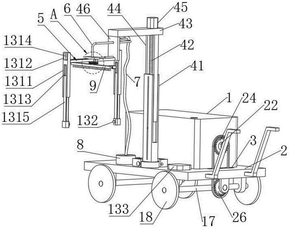
图1为本发明第一视角的整体结构示意图;Fig. 1 is a schematic diagram of the overall structure of the first viewing angle of the present invention;
图2为本发明第二视角的整体结构示意图;2 is a schematic diagram of the overall structure of the second viewing angle of the present invention;
图3为图2中A的放大结构示意图;Fig. 3 is the schematic diagram of the enlarged structure of A in Fig. 2;
图4为本发明中测距组件的结构示意图;Fig. 4 is a schematic structural diagram of a ranging component in the present invention;
图5为本发明的部分结构示意图。Fig. 5 is a partial structural schematic diagram of the present invention.
附图标记说明:Explanation of reference signs:
1、水肥一体箱;2、支撑板;3、限位孔;4、第一调节架;41、支撑杆;42、螺纹柱;43、承接板;44、限位杆;45、第一电机;46、固定板;5、第二调节架;51、导轨;52、移动块;53、第二电动伸缩杆;6、第一连接管;7、水管;8、水泵;9、空心管路;10、转动管;11、喷淋头;12、水流封堵组件;121、滑动塞;122、第一电动伸缩杆;13、测距组件;131、伸缩杆件;1311、固定杆;1312、安装孔;1313、滑动槽;1314、第三电动伸缩杆;1315、移动杆;132、红外测距传感器;133、中央处理器;14、从动齿轮;15、主动齿轮;16、第二电机;17、连接轴;18、滚轮;19、转盘;20、定位块;21、限位框;22、转轴;23、搅拌杆;24、第一链轮;25、链条;26、第二链轮;27、第一锥齿轮;28、第二锥齿轮。1. Water and fertilizer integrated box; 2. Support plate; 3. Limit hole; 4. First adjustment frame; 41. Support rod; 42. Threaded column; 43. Accepting plate; 44. Limit rod; 45. First motor ; 46, fixed plate; 5, the second adjustment frame; 51, guide rail; 52, moving block; 53, the second electric telescopic rod; 6, the first connecting pipe; 7, water pipe; ;10, rotating tube; 11, spray head; 12, water flow blocking assembly; 121, sliding plug; 122, the first electric telescopic rod; 13, distance measuring component; 131, telescopic rod; , mounting hole; 1313, sliding groove; 1314, the third electric telescopic rod; 1315, moving rod; 132, infrared distance measuring sensor; 133, central processing unit; 14, driven gear; 15, driving gear; 16, second Motor; 17, connecting shaft; 18, roller; 19, turntable; 20, positioning block; 21, limit frame; 22, rotating shaft; 23, stirring rod; 24, first sprocket wheel; 25, chain; 26, second Sprocket wheel; 27, the first bevel gear; 28, the second bevel gear.
具体实施方式detailed description
为了使本发明的目的、技术方案及优点更加清楚明白,以下结合附图及实施例,对本发明进行进一步详细说明。应当理解,此处所描述的具体实施例仅仅用以解释本发明,并不用于限定本发明。In order to make the object, technical solution and advantages of the present invention clearer, the present invention will be further described in detail below in conjunction with the accompanying drawings and embodiments. It should be understood that the specific embodiments described here are only used to explain the present invention, not to limit the present invention.
基于本发明中的实施例,本领域普通技术人员在没有作出创造性劳动前提下所获得的所有其他实施例,都属于本发明保护的范围。Based on the embodiments of the present invention, all other embodiments obtained by persons of ordinary skill in the art without creative efforts fall within the protection scope of the present invention.
另外,本发明各个实施例之间的技术方案可以相互结合,但是必须是以本领域普通技术人员能够实现为基础,当技术方案的结合出现相互矛盾或无法实现时应当认为这种技术方案的结合不存在,也不在本发明要求的保护范围之内。In addition, the technical solutions of the various embodiments of the present invention can be combined with each other, but it must be based on the realization of those skilled in the art. When the combination of technical solutions is contradictory or cannot be realized, it should be considered as a combination of technical solutions. Does not exist, nor is it within the scope of protection required by the present invention.
实施例1Example 1
参见图1至图4所示,为了实现在对盆栽培养的植物进行浇水的过程中,能够有效根据盆栽的直径大小来控制喷淋的范围,从而既能够节约水资源,同时也可减少水流溅出盆栽外面对种植园场地的污染,打造更加环抱的园艺种植用具,本实施例提供一种环保型园艺种植用植物浇水装置,包括移动体,移动体包括支撑板2,支撑板2下侧安装有至少两个水平设置的连接轴17,连接轴17的两端设有滚轮18,支撑板2的侧壁还开设有限位孔3。进而在支撑板2上设有水肥一体箱1,水肥一体箱1可同于后续对营养水或水溶肥料的储存,进而在支撑板2上安装有第一调节架4,第一调节架4背离支撑板2的一端固定有第二调节架5,第二调节架5整体呈水平设置,第二调节架5的移动件上插设第一连接管6,第一连接管6一端通过水管7与水肥一体箱1上的水泵8连接,进而在第二调节架5的移动件下侧转动连接有转动管10,转动管10的下侧固定有空心管路9,空心管路9的下侧等间距分布有若干喷淋头11,喷淋头11安装在空心管路9上与之对应的走水孔内,较优的是喷淋头11在空心管上的密度应满足喷淋需求,相邻两个喷淋头11应小于10cm,进而在空心管路9的两端口部分别设有一个水流封堵组件12,通过两个水流封堵组件12可用于对空心管路9装水体积的控制,即实现调节不同数量的喷淋头11出水,进而在第二调节架5且与其移动件移动方向垂直的两端分别设置有一个测距组件13,与两个水流封堵组件12一一对应,通过测距组件13能够测量出其到盆栽中盆体的直径,从而和水流封堵组件12配合使其调节喷淋头11的使用数量。Referring to Fig. 1 to Fig. 4, in order to realize the process of watering potted plants, the range of spraying can be effectively controlled according to the diameter of potted plants, so as to save water resources and reduce water flow Splashing out the pollution of the potted plant to the plantation site creates a more enveloping gardening planting tool. This embodiment provides an environmentally friendly plant watering device for gardening planting, including a moving body. The moving body includes a
参见图1和图2所示,在本发明的实施例中,上述的测距组件13包括两个竖直设置的伸缩杆件131,并且两者分别设置于第二调节架5的两端,两个伸缩杆件131下端的相对侧壁上均固定连接有红外测距传感器132,红外测距传感器132用于测量其到盆栽本体的水平距离,红外测距传感器132电连接有中央处理器133,中央处理器133的控制单元与水流封堵组件12电连接。通过两个伸缩杆件131的调节可实现红外测距传感器132适应不同高度的盆栽本体,进而两侧的红外测距传感器132分别测出其到盆栽本体的具体距离,进而将数据传输给中央处理器133进行分析,通过控制单元控制水流封堵组件12启动对空心管路9的应用体积的调节。Referring to Fig. 1 and Fig. 2, in the embodiment of the present invention, the
参见图1和图4所示,在本发明的实施例中,水流封堵组件12包括滑动塞121和第一电动伸缩杆122,滑动塞121在空心管路9中滑动,第一电动伸缩杆122的输出端穿过空心管路9端部的侧壁且与滑动塞121固定,第一电动伸缩杆122背离滑动塞121的一端与空心管路9的外侧壁固定,第一电动伸缩杆122与中央处理器133的控制单元电连接。1 and 4, in an embodiment of the present invention, the water
在使用时,首先通过第一调节架4和第二调节架5将空心管路9调节至盆栽本体的正上方,盆栽本体处于空心管路的中间位置,此时两个测距组件13处于盆栽本体的相对两侧,通过对伸缩杆件131的调节使得两个红外测距传感器132到达盆栽本体的合适位置,进而启动红外测距传感器132测出各自到盆栽本体的距离,即每个红外测距传感器132测出的距离即为对应的滑动塞121需要移动的距离,进而将测出距离信息传输给中央处理器133,中央处理器133经过数据分析通过控制单元对两个第一电动伸缩杆122进行启动,实现空心管路9中两个滑动塞121相向移动对空心管路9的空间缩小,此时启动水泵8对空心管路9中供水,并且进入空心管路9的水流处于两个滑动塞121之间,即此时只有两个滑动塞121之间的喷淋头11出水对下方的植物浇水,有效的实现了喷淋范围的控制,避免所有喷淋头11的打开对水资源的浪费,同时也减少了水流溅出盆栽本体的水量。并且在移动体的前进过程中喷头11的打开数量会在红外测距传感器132和中央处理器133的配合下自动改变,使得浇水工作更加智能化。When in use, the
实施例2Example 2
参见图1和图2所示,在本发明的实施例中,为了进一步提高本装置在对盆栽植物浇水的应用和适用范围,第一调节架4包括竖直安装在移动体上的支撑杆41,且支撑杆41为空心设置,支撑杆41内插设并螺接有螺纹柱42,螺纹柱42的上端延伸出支撑杆41且固定连接有承接板43,承接板43面向支撑杆41的一侧还固定连接有两个竖直设置的限位杆44,限位杆44与支撑杆41的侧壁滑动,用于对承接板43进行转动限位,承接板43的上侧固定连接有第一电机45,第一电机45的输出端与螺纹柱42固定连接,承接板43背离支撑杆41的一侧通过固定板46与第二调节架5连接。Referring to Fig. 1 and Fig. 2, in an embodiment of the present invention, in order to further improve the application and scope of application of the device for watering potted plants, the
在对盆栽植物进行浇水时,通过第一电机45驱动螺纹柱42转动,可使得承接板43实现升降,间接的带动喷淋头11升降,可有效的根据不同盆栽植物的高度进行有效调节,提高装置的适用范围。When watering the potted plants, the threaded
实施例3Example 3
参见图1和图2所示,在本发明的实施例中,为了增大装置的适用范围,避免装置的喷淋功能的局限。第二调节架5包括水平设置的导轨51,导轨51与固定板46固定,固定板46垂直于导轨51,导轨51内滑动连接有移动块52,移动块52一侧固定在第二电动伸缩杆53的输出端,第二电动伸缩杆53固定在导轨51的侧壁上,第一连接管6插设在移动块52上,并且第一连接管6的下端穿过转动管10与空心管路9连通,第一连接管6与空心管路9的连接部转动连接,连接杆背离空心管路9的一端与水管7连接,水管7为有足够预留长度的挠性管,进而为了提高水管7的稳定性,水管7在安装时穿过固定板46上的通孔并能在其中进行抽拉,保证移动件在导轨51上的移动不受限,两个伸缩杆件131分别设置在导轨51的两端。通过第二电动伸缩杆53的启动可以实现空心管路9的整体喷淋范围。Referring to Fig. 1 and Fig. 2, in the embodiment of the present invention, in order to increase the applicable range of the device, the limitation of the spraying function of the device is avoided. The
参见图2所示,在本发明的实施例中,伸缩杆件131包括固定杆1311,固定杆1311上开设有安装孔1312和滑动槽1313,安装孔1312内固定有第三电动伸缩杆1314,第三电动伸缩杆1314的输出端穿过安装孔1312和滑动槽1313之间的侧壁并固定有移动杆1315,移动杆1315在滑动槽1313内滑动,并且滑动槽1313的下端与红外测距传感器132固定,在两个伸缩杆件131中其中一个固定杆1311与导轨51靠近移动体一端固定,另一个固定杆1311与导轨51背离移动体的一端通过螺栓可拆卸连接。通过第三电动伸缩杆1314的可实现对红外测距传感器132的竖直高度调节,便于后续在对不同规格的盆栽浇水时可进行适应性的调整。Referring to Fig. 2, in an embodiment of the present invention, the
在园艺种植中当需要对成片土地上种植的植物进行浇水时,将远离移动体一侧的伸缩杆件131拆卸下来,进而通过第二电动伸缩杆53可使得移动块52在导轨51内进行左右移动,从而可使得移动块52带动空心管路增大喷淋范围,并且此时通过第一电动伸缩杆122将滑动塞121恢复到初始位置,即滑动塞121处于空心管路的端部,能够保证所有的喷淋头11打开对植物浇水,有效的提高本装置的使用环境和功能性。较优的是该应用场景无需启动测距组件13。In horticultural planting, when it is necessary to water the plants planted on the piece of land, the
实施例4Example 4
参见图1和图3所示,在本发明的实施例中,转动管10上套装固定有从动齿轮14,从动齿轮14啮合有主动齿轮15,主动齿轮15固定在第二电机16的输出端,第二电机16固定在移动块52上。Referring to Fig. 1 and Fig. 3, in an embodiment of the present invention, a driven
在使用时,将空心管路9移动至需要浇水的盆栽植物正上方,并且将转动管10的位置调至盆栽植物所处的位置之内,即保证空心管路9中的每一个滑动塞121的操作调节不会超过转动管10的位置,进而当水流封堵组件12对喷淋头11的数量做好调整后,启动水泵8对应用的喷头进行补水的同时,启动第二电机16,此时第二电机16为主动齿轮15提供驱动力,在主动齿轮15和从动齿轮14的啮合下使得空心管路开始转动,并且能够带动喷淋头11转动,从而实现对每一个盆栽植物进行充分的浇水,进一步的技能减少水流溢出盆栽的水量,同时也保证了每个盆栽的浇水面更加适应盆栽本体的喷口。When in use, move the
实施例5Example 5
参见图1所示,在本发明的实施例中,支撑杆41的下侧固定连接有转盘19,转动盘与支撑板2转动连接,转盘19的周侧固定有一个定位块20,支撑板2上固定有一个限位框21,定位块20在限位框21内进行90度旋转,并且定位块20通过螺栓与限位框21的两个不同侧壁可拆卸连接。Referring to Fig. 1, in an embodiment of the present invention, the lower side of the
在使用时,通过对支撑杆41向外转动使得定位件与限位框21靠近支撑板2边缘的侧壁固定,此时方便对植物浇水,当浇完水后通过将支撑杆41向内转动90度使得定位件与限位框21的另一个侧壁固定可使得第一支撑架、第二支撑架、空心管路9以及两个伸缩杆件131靠在水肥一体箱1一侧,减小装置的存放空间。When in use, the positioning member and the
实施例6Example 6
参见图2和图5所示,在本发明的实施例中,水肥一体箱1内转动连接有转轴22,转轴22上固定有搅拌杆23,转轴22一端延伸出水肥一体箱1套装固定有第一链轮24,第一链轮24通过链条25连接有第二链轮26,第二链轮26设置在支撑板2底部,链条25穿过限位孔3设置,并且链轮通过稳定板与支撑板2转动连接,链轮一侧固定连接有第一锥齿轮27,第一锥齿轮27啮合有第二锥齿轮28,第二锥齿轮28套装固定在一个连接轴17上。Referring to Fig. 2 and Fig. 5, in the embodiment of the present invention, the water and fertilizer integrated
在使用时,当水肥一体箱1内储存的是水溶肥料时,为了降低物体未溶解的肥料沉淀,推动支撑板2实现滚轮18带动连接轴17转动,此时连接轴17在第一锥齿轮27和第二锥齿轮28的配合下间接的带动第二链轮26转动,进而第二链轮26通过链条25实现第一链轮24带动转轴22转动,从而可使得转轴22带动搅拌杆23对水肥一体箱1内的肥料进行搅拌,从而使得水肥一体箱1内固体肥料充分溶解,水肥混合更加充分,使得装置在移动的过程又能有效的实现水肥一体箱1内水肥的搅拌,避免了人工搅拌的费时费力,结构简单。When in use, when water-soluble fertilizers are stored in the water and fertilizer integrated
显然,本领域的技术人员可以对本发明进行各种改动和变型而不脱离本发明的精神和范围。这样,倘若本发明的这些修改和变型属于本发明权利要求及其等同技术的范围之内,则本发明也意图包含这些改动和变型在内。Obviously, those skilled in the art can make various changes and modifications to the present invention without departing from the spirit and scope of the present invention. Thus, if these modifications and variations of the present invention fall within the scope of the claims of the present invention and their equivalent technologies, the present invention also intends to include these modifications and variations.
Claims (10)
Priority Applications (1)
| Application Number | Priority Date | Filing Date | Title |
|---|---|---|---|
| CN202211399291.7A CN115606388A (en) | 2022-11-09 | 2022-11-09 | An environment-friendly plant watering device for horticultural planting |
Applications Claiming Priority (1)
| Application Number | Priority Date | Filing Date | Title |
|---|---|---|---|
| CN202211399291.7A CN115606388A (en) | 2022-11-09 | 2022-11-09 | An environment-friendly plant watering device for horticultural planting |
Publications (1)
| Publication Number | Publication Date |
|---|---|
| CN115606388A true CN115606388A (en) | 2023-01-17 |
Family
ID=84878206
Family Applications (1)
| Application Number | Title | Priority Date | Filing Date |
|---|---|---|---|
| CN202211399291.7A Withdrawn CN115606388A (en) | 2022-11-09 | 2022-11-09 | An environment-friendly plant watering device for horticultural planting |
Country Status (1)
| Country | Link |
|---|---|
| CN (1) | CN115606388A (en) |
Cited By (1)
| Publication number | Priority date | Publication date | Assignee | Title |
|---|---|---|---|---|
| CN119073076A (en) * | 2024-11-04 | 2024-12-06 | 西南林业大学 | An integrated equipment for water and fertilizer application in olive orchards |
-
2022
- 2022-11-09 CN CN202211399291.7A patent/CN115606388A/en not_active Withdrawn
Cited By (2)
| Publication number | Priority date | Publication date | Assignee | Title |
|---|---|---|---|---|
| CN119073076A (en) * | 2024-11-04 | 2024-12-06 | 西南林业大学 | An integrated equipment for water and fertilizer application in olive orchards |
| CN119073076B (en) * | 2024-11-04 | 2025-01-24 | 西南林业大学 | Water fertilization integrated equipment for olive garden |
Similar Documents
| Publication | Publication Date | Title |
|---|---|---|
| CN203233769U (en) | Intelligent plant cultivation device | |
| CN116076217A (en) | Fertilizing equipment for seedlings of daylily inverted water lily | |
| CN111527947B (en) | Water and fertilizer integrated irrigation system for greenhouse planting | |
| CN218184245U (en) | Crop seedling raising device | |
| CN210928601U (en) | Fertilizer injection unit is used in greenhouse vegetable cultivation | |
| CN111406549A (en) | Multi-functional flower nursery planting machine of rail mounted | |
| CN212212072U (en) | A breeding device for farming | |
| CN215836319U (en) | A simple and easy formula fertilizer water medicine integral type is drip irrigation in coordination and is put for strawberry is planted | |
| CN116195498A (en) | A seedling automatic fertilization and spraying device and using method | |
| CN214206577U (en) | Seed breeding device | |
| CN211322406U (en) | Agricultural is grown seedlings and uses irrigation equipment | |
| CN102845292A (en) | Rotary aeroponic cultivation device | |
| CN210746549U (en) | Aerial fog planting equipment | |
| CN202285755U (en) | Rotary type aerial fog cultivation device | |
| CN114208655A (en) | Vegetable aeroponic cultivation device with seedling raising and foliar fertilization functions | |
| CN212697018U (en) | Grow seedlings with portable watering device | |
| CN222548043U (en) | A water-saving fertilization device for corn planting | |
| CN221241058U (en) | Greenhouse spraying equipment | |
| CN215380464U (en) | Automatic intelligent irrigation unit | |
| CN222322389U (en) | A cultivation and management device for intercropping corn and breeding Notopterygium wilfordii seedlings | |
| CN214545622U (en) | A crop seedling fertilizing equipment | |
| CN218353255U (en) | Chemical fertilizer sprinkler | |
| CN215873205U (en) | Hami melon sprinkling irrigation equipment | |
| CN223437487U (en) | Municipal afforestation cultivation device | |
| CN117426193B (en) | A water and fertilizer integrated irrigation device for fruit tree planting |
Legal Events
| Date | Code | Title | Description |
|---|---|---|---|
| PB01 | Publication | ||
| PB01 | Publication | ||
| SE01 | Entry into force of request for substantive examination | ||
| SE01 | Entry into force of request for substantive examination | ||
| WW01 | Invention patent application withdrawn after publication | ||
| WW01 | Invention patent application withdrawn after publication |
Application publication date: 20230117 |