CN115596950A - Measuring device for construction with adjustable light source angle - Google Patents
Measuring device for construction with adjustable light source angle Download PDFInfo
- Publication number
- CN115596950A CN115596950A CN202211387874.8A CN202211387874A CN115596950A CN 115596950 A CN115596950 A CN 115596950A CN 202211387874 A CN202211387874 A CN 202211387874A CN 115596950 A CN115596950 A CN 115596950A
- Authority
- CN
- China
- Prior art keywords
- rod
- fixedly connected
- light source
- movable plate
- measuring device
- Prior art date
- Legal status (The legal status is an assumption and is not a legal conclusion. Google has not performed a legal analysis and makes no representation as to the accuracy of the status listed.)
- Granted
Links
Images


Classifications
-
- F—MECHANICAL ENGINEERING; LIGHTING; HEATING; WEAPONS; BLASTING
- F16—ENGINEERING ELEMENTS AND UNITS; GENERAL MEASURES FOR PRODUCING AND MAINTAINING EFFECTIVE FUNCTIONING OF MACHINES OR INSTALLATIONS; THERMAL INSULATION IN GENERAL
- F16M—FRAMES, CASINGS OR BEDS OF ENGINES, MACHINES OR APPARATUS, NOT SPECIFIC TO ENGINES, MACHINES OR APPARATUS PROVIDED FOR ELSEWHERE; STANDS; SUPPORTS
- F16M11/00—Stands or trestles as supports for apparatus or articles placed thereon ; Stands for scientific apparatus such as gravitational force meters
- F16M11/02—Heads
- F16M11/04—Means for attachment of apparatus; Means allowing adjustment of the apparatus relatively to the stand
- F16M11/043—Allowing translations
- F16M11/046—Allowing translations adapted to upward-downward translation movement
-
- F—MECHANICAL ENGINEERING; LIGHTING; HEATING; WEAPONS; BLASTING
- F16—ENGINEERING ELEMENTS AND UNITS; GENERAL MEASURES FOR PRODUCING AND MAINTAINING EFFECTIVE FUNCTIONING OF MACHINES OR INSTALLATIONS; THERMAL INSULATION IN GENERAL
- F16M—FRAMES, CASINGS OR BEDS OF ENGINES, MACHINES OR APPARATUS, NOT SPECIFIC TO ENGINES, MACHINES OR APPARATUS PROVIDED FOR ELSEWHERE; STANDS; SUPPORTS
- F16M11/00—Stands or trestles as supports for apparatus or articles placed thereon ; Stands for scientific apparatus such as gravitational force meters
- F16M11/02—Heads
- F16M11/04—Means for attachment of apparatus; Means allowing adjustment of the apparatus relatively to the stand
- F16M11/06—Means for attachment of apparatus; Means allowing adjustment of the apparatus relatively to the stand allowing pivoting
- F16M11/10—Means for attachment of apparatus; Means allowing adjustment of the apparatus relatively to the stand allowing pivoting around a horizontal axis
-
- F—MECHANICAL ENGINEERING; LIGHTING; HEATING; WEAPONS; BLASTING
- F16—ENGINEERING ELEMENTS AND UNITS; GENERAL MEASURES FOR PRODUCING AND MAINTAINING EFFECTIVE FUNCTIONING OF MACHINES OR INSTALLATIONS; THERMAL INSULATION IN GENERAL
- F16M—FRAMES, CASINGS OR BEDS OF ENGINES, MACHINES OR APPARATUS, NOT SPECIFIC TO ENGINES, MACHINES OR APPARATUS PROVIDED FOR ELSEWHERE; STANDS; SUPPORTS
- F16M11/00—Stands or trestles as supports for apparatus or articles placed thereon ; Stands for scientific apparatus such as gravitational force meters
- F16M11/02—Heads
- F16M11/18—Heads with mechanism for moving the apparatus relatively to the stand
-
- F—MECHANICAL ENGINEERING; LIGHTING; HEATING; WEAPONS; BLASTING
- F16—ENGINEERING ELEMENTS AND UNITS; GENERAL MEASURES FOR PRODUCING AND MAINTAINING EFFECTIVE FUNCTIONING OF MACHINES OR INSTALLATIONS; THERMAL INSULATION IN GENERAL
- F16M—FRAMES, CASINGS OR BEDS OF ENGINES, MACHINES OR APPARATUS, NOT SPECIFIC TO ENGINES, MACHINES OR APPARATUS PROVIDED FOR ELSEWHERE; STANDS; SUPPORTS
- F16M11/00—Stands or trestles as supports for apparatus or articles placed thereon ; Stands for scientific apparatus such as gravitational force meters
- F16M11/42—Stands or trestles as supports for apparatus or articles placed thereon ; Stands for scientific apparatus such as gravitational force meters with arrangement for propelling the support stands on wheels
-
- G—PHYSICS
- G01—MEASURING; TESTING
- G01B—MEASURING LENGTH, THICKNESS OR SIMILAR LINEAR DIMENSIONS; MEASURING ANGLES; MEASURING AREAS; MEASURING IRREGULARITIES OF SURFACES OR CONTOURS
- G01B5/00—Measuring arrangements characterised by the use of mechanical techniques
- G01B5/24—Measuring arrangements characterised by the use of mechanical techniques for measuring angles or tapers; for testing the alignment of axes
-
- G—PHYSICS
- G01—MEASURING; TESTING
- G01S—RADIO DIRECTION-FINDING; RADIO NAVIGATION; DETERMINING DISTANCE OR VELOCITY BY USE OF RADIO WAVES; LOCATING OR PRESENCE-DETECTING BY USE OF THE REFLECTION OR RERADIATION OF RADIO WAVES; ANALOGOUS ARRANGEMENTS USING OTHER WAVES
- G01S17/00—Systems using the reflection or reradiation of electromagnetic waves other than radio waves, e.g. lidar systems
- G01S17/02—Systems using the reflection of electromagnetic waves other than radio waves
- G01S17/06—Systems determining position data of a target
- G01S17/08—Systems determining position data of a target for measuring distance only
-
- Y—GENERAL TAGGING OF NEW TECHNOLOGICAL DEVELOPMENTS; GENERAL TAGGING OF CROSS-SECTIONAL TECHNOLOGIES SPANNING OVER SEVERAL SECTIONS OF THE IPC; TECHNICAL SUBJECTS COVERED BY FORMER USPC CROSS-REFERENCE ART COLLECTIONS [XRACs] AND DIGESTS
- Y02—TECHNOLOGIES OR APPLICATIONS FOR MITIGATION OR ADAPTATION AGAINST CLIMATE CHANGE
- Y02E—REDUCTION OF GREENHOUSE GAS [GHG] EMISSIONS, RELATED TO ENERGY GENERATION, TRANSMISSION OR DISTRIBUTION
- Y02E10/00—Energy generation through renewable energy sources
- Y02E10/50—Photovoltaic [PV] energy
Landscapes
- Engineering & Computer Science (AREA)
- General Engineering & Computer Science (AREA)
- Mechanical Engineering (AREA)
- Physics & Mathematics (AREA)
- General Physics & Mathematics (AREA)
- Electromagnetism (AREA)
- Computer Networks & Wireless Communication (AREA)
- Radar, Positioning & Navigation (AREA)
- Remote Sensing (AREA)
- Length Measuring Devices By Optical Means (AREA)
Abstract
本发明涉及测量装置技术领域,本发明公开了一种光源角度可调的建筑施工用测量装置,包括底座,所述底座的上方设置有上下调节组件,上下调节组件上设置有活动板,活动板的背面固定连接有支撑柱,支撑柱的另一端固定连接有靠板,活动板的左右两侧均通过转轴转动连接有支撑杆,支撑杆远离活动板的一端固定连接有安装箱,安装箱的下方通过旋转调节组件设置有激光测距仪,活动板的正面设置有用于带动支撑杆绕转轴旋转的收放组件;本发明激光测距仪发出光束照射到墙体上,接着旋转调节组件对激光测距仪的光源角度进行调整,通过距离和角度计算出墙角的角度,从而对较长的墙体进行测量,提高测量结果的准确性。
The invention relates to the technical field of measuring devices. The invention discloses a measuring device for building construction with an adjustable light source angle. The back of the support column is fixedly connected with a support column, the other end of the support column is fixedly connected with a backing plate, the left and right sides of the movable plate are connected with a support rod through a rotating shaft, and the end of the support rod far away from the movable plate is fixedly connected with a mounting box. The lower part is provided with a laser rangefinder through the rotating adjustment assembly, and the front of the movable plate is provided with a retractable assembly for driving the support rod to rotate around the axis of rotation; The angle of the light source of the rangefinder is adjusted, and the angle of the wall corner is calculated through the distance and angle, so as to measure the longer wall and improve the accuracy of the measurement result.
Description
技术领域technical field
本发明涉及测量装置技术领域,具体为一种光源角度可调的建筑施工用测量装置。The invention relates to the technical field of measuring devices, in particular to a measuring device for building construction with an adjustable light source angle.
背景技术Background technique
建筑物是满足人们生产、居住、学习、公共活动需要的工程,在建筑工程施工过程中需要对砌筑墙体的墙角角度进行测量;现有的测量方式一般通过量角器进行测量。A building is a project that meets the needs of people's production, living, learning, and public activities. During the construction process of a building project, it is necessary to measure the corner angle of the masonry wall; the existing measurement method is generally measured by a protractor.
而量角器可以画角度、量角度、画垂直线、平行线、测倾斜度、垂直度、水平度,可以当内外直角拐尺,可当长短直尺还能够直观读出,并画出规定尺寸的角,对于建筑施工来说,具有广泛用途。The protractor can draw angles, measure angles, draw vertical lines, parallel lines, measure inclination, verticality, and levelness. Corners have a wide range of uses for building construction.
采用量角器在测量高处的墙角时需要借助外界工具比如梯子,当使用者测量角度时,需要站在梯子上将量角器放到合适的高度,这样的测量方式一个人手持量角器进行测量还要读数记录,操作不便,给使用者带来了极大的不便,而且频繁的登高操作往往很不安全,存在一定的安全隐患。When using a protractor to measure a high wall corner, you need to use external tools such as a ladder. When the user measures the angle, you need to stand on the ladder and place the protractor at a suitable height. In this measurement method, one person holds the protractor to measure and also needs to record the reading. , the operation is inconvenient, which brings great inconvenience to the user, and frequent climbing operations are often very unsafe, and there are certain safety hazards.
发明内容Contents of the invention
本发明要解决的技术问题在于提供了一种光源角度可调的建筑施工用测量装置,以解决上述背景技术中提出的现有量角器对墙角进行测量时,由于量角器两侧的靠杆不可能做的很长,当墙角处的墙体较长时,导致测量的结果不够准确的问题。The technical problem to be solved by the present invention is to provide a measuring device for building construction with an adjustable light source angle, so as to solve the problem that when the existing protractor proposed in the above-mentioned background technology measures the corner of a wall, it is impossible to do it due to the leaning bars on both sides of the protractor. It is very long, when the wall at the corner is longer, the measurement result is not accurate enough.
为解决上述技术问题,本发明提供如下技术方案:In order to solve the above technical problems, the present invention provides the following technical solutions:
一种光源角度可调的建筑施工用测量装置,包括底座,所述底座的上方设置有上下调节组件,上下调节组件上设置有活动板,活动板的背面固定连接有支撑柱,支撑柱的另一端固定连接有靠板,活动板的左右两侧均通过转轴转动连接有支撑杆,支撑杆远离活动板的一端固定连接有安装箱,安装箱的下方通过旋转调节组件设置有激光测距仪,活动板的正面设置有用于带动支撑杆绕转轴旋转的收放组件。A measuring device for building construction with an adjustable light source angle, comprising a base, an up and down adjustment assembly is arranged above the base, a movable plate is arranged on the up and down adjustment assembly, a support column is fixedly connected to the back of the movable plate, and another support column is connected to the support column. One end is fixedly connected with the backing plate, the left and right sides of the movable plate are connected with the support rod through the rotating shaft, the end of the support rod far away from the movable plate is fixedly connected with the installation box, and the laser range finder is arranged under the installation box through the rotation adjustment component. The front of the movable plate is provided with a retractable assembly for driving the support rod to rotate around the rotating shaft.
以下是本发明对上述技术方案的进一步优化:Below is the further optimization of the present invention to above-mentioned technical scheme:
所述底座的内部开设有空腔,空腔的内部安装有蓄电池,底座的下表面四角均安装有万向轮,底座的上表面前侧固定连接有推杆,推杆的顶端固定连接有扶手。There is a cavity inside the base, a battery is installed inside the cavity, universal wheels are installed on the four corners of the lower surface of the base, a push rod is fixedly connected to the front side of the upper surface of the base, and a handrail is fixedly connected to the top of the push rod .
进一步优化:所述上下调节组件包括第一电机和第一丝杆,第一电机固定连接在底座的上表面,第一丝杆的底端与第一电机的输出端固定连接,第一丝杆的顶端贯穿活动板并通过轴承转动连接有第一固定板,第一丝杆与活动板螺纹连接。Further optimization: the up and down adjustment assembly includes a first motor and a first screw rod, the first motor is fixedly connected to the upper surface of the base, the bottom end of the first screw rod is fixedly connected to the output end of the first motor, and the first screw rod The top end of the movable plate passes through the movable plate and is rotatably connected with the first fixed plate through the bearing, and the first screw rod is threadedly connected with the movable plate.
进一步优化:第一丝杆的两侧均设置有第一导向杆,第一导向杆的底端与底座的上表面固定连接,第一导向杆的顶端贯穿活动板并与第一固定板固定连接,第一导向杆与活动板滑动连接。Further optimization: first guide rods are provided on both sides of the first screw rod, the bottom end of the first guide rod is fixedly connected with the upper surface of the base, and the top end of the first guide rod penetrates the movable plate and is fixedly connected with the first fixed plate , the first guide rod is slidingly connected with the movable plate.
进一步优化:所述靠板远离支撑柱的一侧面开设有V形槽,所述V形槽的角度为钝角,V形槽和激光测距仪位于同一平面,V形槽和激光测距仪均突出底座的背面。Further optimization: a V-shaped groove is provided on the side of the backing plate away from the support column, the angle of the V-shaped groove is an obtuse angle, the V-shaped groove and the laser range finder are located on the same plane, and the V-shaped groove and the laser range finder are both Highlight the back of the base.
进一步优化:所述支撑杆呈L形,支撑杆的上表面安装有气泡检测仪。Further optimization: the support rod is L-shaped, and a bubble detector is installed on the upper surface of the support rod.
进一步优化:所述旋转调节组件包括旋转杆、蜗轮、蜗杆和把手,旋转杆的底端贯穿安装箱的下表面并与激光测距仪固定连接,旋转杆通过轴承与安装箱转动连接,蜗轮位于安装箱的内部并固定连接在旋转杆的外表面,蜗杆与蜗轮啮合连接,蜗杆远离蜗轮的一端贯穿安装箱并与把手固定连接,蜗杆通过轴承与安装箱转动连接。Further optimization: the rotation adjustment assembly includes a rotating rod, a worm gear, a worm and a handle. The bottom end of the rotating rod penetrates the lower surface of the installation box and is fixedly connected with the laser rangefinder. The rotating rod is rotationally connected with the installation box through a bearing. The inside of the installation box is fixedly connected to the outer surface of the rotating rod. The worm is meshed with the worm gear. The end of the worm away from the worm wheel passes through the installation box and is fixedly connected with the handle.
进一步优化:所述旋转杆的顶端延伸至安装箱的上表面并固定连接有指针,所述安装箱的上表面开设有与指针相对应的刻度线。Further optimization: the top end of the rotating rod extends to the upper surface of the installation box and is fixedly connected with a pointer, and the upper surface of the installation box is provided with a scale line corresponding to the pointer.
进一步优化:所述收放组件包括安装板、第二电机、第二丝杆和活动杆,安装板与活动板的正面固定连接,第二电机固定连接在安装板的上表面,第二丝杆的底端与第二电机的输出端固定连接,第二丝杆的顶端贯穿活动杆并通过轴承转动连接有第二固定板,第二丝杆与活动杆螺纹连接,活动杆的左右两侧均通过销轴转动连接有引导杆,引导杆远离活动杆的一端通过销轴与支撑杆转动连接。Further optimization: the retractable assembly includes a mounting plate, a second motor, a second screw and a movable rod, the mounting plate is fixedly connected to the front of the movable plate, the second motor is fixedly connected to the upper surface of the mounting plate, and the second screw rod The bottom end of the second motor is fixedly connected with the output end of the second motor, the top of the second screw rod runs through the movable rod and is connected with the second fixed plate through the bearing rotation, the second screw rod is threadedly connected with the movable rod, and the left and right sides of the movable rod are The guide rod is rotatably connected with the pin shaft, and the end of the guide rod away from the movable rod is rotatably connected with the support rod through the pin shaft.
进一步优化:所述第二丝杆的左右两侧均设置有第二导向杆,第二导向杆的底端与安装板固定连接,第二导向杆的顶端贯穿活动杆并与第二固定板固定连接,第二导向杆与活动杆滑动连接。Further optimization: the left and right sides of the second screw rod are provided with a second guide rod, the bottom end of the second guide rod is fixedly connected with the mounting plate, and the top end of the second guide rod passes through the movable rod and is fixed with the second fixed plate connected, the second guide rod is slidably connected with the movable rod.
本发明采用上述技术方案,具有以下有益效果:The present invention adopts the above-mentioned technical scheme, and has the following beneficial effects:
1、该光源角度可调的建筑施工用测量装置,通过第二电机带动第二丝杆旋转,第二丝杆在旋转的过程中能够带动活动杆沿着第二导向杆向下移动,活动杆在移动的过程中通过引导杆带动支撑杆绕转轴旋转,直至观察气泡检测仪使支撑杆呈水平状态,从而方便进行测量,在不使用时将其旋转到竖直状态,从而减小该装置的体积,方便穿过狭小的空间进行使用。1. The measuring device for building construction with an adjustable light source angle drives the second screw to rotate through the second motor. During the rotation, the second screw can drive the movable rod to move downward along the second guide rod. The movable rod In the process of moving, the guide rod drives the support rod to rotate around the rotating shaft until the support rod is in a horizontal state by observing the bubble detector, so as to facilitate measurement, and it is rotated to a vertical state when not in use, thereby reducing the device's The volume makes it easy to use through tight spaces.
2、该光源角度可调的建筑施工用测量装置,通过第一电机带动第一丝杆旋转,第一丝杆在旋转的过程中能够带动活动板沿着第一导向杆向上移动,活动板在移动的过程中能够使支撑杆和激光测距仪移动到需要测量的高度,从而对不同高度的墙角进行测量。2. The measurement device for building construction with adjustable light source angle drives the first screw to rotate through the first motor. During the rotation, the first screw can drive the movable plate to move upward along the first guide rod. During the moving process, the support rod and the laser range finder can be moved to the height to be measured, so as to measure the corners of different heights.
3、该光源角度可调的建筑施工用测量装置,通过激光测距仪发出光束照射到墙角处的墙体上,接着转动把手带动蜗杆旋转,蜗杆在旋转的过程中与蜗轮配合能够带动旋转杆旋转,旋转杆在旋转的过程中能够带动激光测距仪和指针旋转,直至激光测距仪计算出与墙体远端的距离,同时观察指针在刻度线处的位置得出激光测距仪旋转的角度,从而对激光测距仪的光源角度进行调整,由于激光测距仪与墙角处的距离固定,并且激光测距仪、墙角和墙面远端之间形成三角形,此时激光测距仪对两侧的墙面测量后通过距离和角度能够计算出墙角的角度,从而能够对较长的墙体进行测量,提高测量结果的准确性。3. The measuring device for building construction with adjustable light source angle emits a beam of light through the laser range finder to irradiate the wall at the corner, and then turns the handle to drive the worm to rotate. During the rotation, the worm cooperates with the worm wheel to drive the rotating rod Rotate, the rotating rod can drive the laser rangefinder and the pointer to rotate during the rotation until the laser rangefinder calculates the distance from the far end of the wall, and at the same time observe the position of the pointer at the scale line to obtain the rotation of the laser rangefinder , so as to adjust the light source angle of the laser rangefinder. Since the distance between the laser rangefinder and the corner is fixed, and a triangle is formed between the laser rangefinder, the corner and the far end of the wall, the laser rangefinder at this time After measuring the walls on both sides, the angle of the wall corner can be calculated through the distance and angle, so that longer walls can be measured and the accuracy of the measurement results can be improved.
下面结合附图和实施例对本发明进一步说明。The present invention will be further described below in conjunction with the accompanying drawings and embodiments.
附图说明Description of drawings
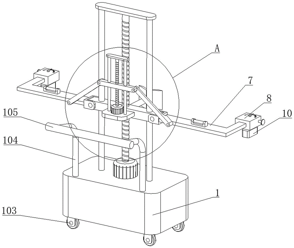
图1为本发明实施例1的总体结构示意图;Fig. 1 is the overall structure schematic diagram of
图2为本发明实施例1中总体结构的立体图;2 is a perspective view of the overall structure in
图3为图1中A处的1局部放大图;Fig. 3 is a partial enlarged view of 1 at A in Fig. 1;
图4为本发明实施例1中总体结构的主视图;Fig. 4 is the front view of the overall structure in
图5为本发明实施例1中测量时的结构示意图;Fig. 5 is the structural representation when measuring in
图6为本发明实施例1中支撑杆的立体图;6 is a perspective view of a support rod in
图7为本发明实施例1中安装箱的内部结构示意图;7 is a schematic diagram of the internal structure of the installation box in
图8为本发明实施例2中旋转调节组件的结构示意图。Fig. 8 is a schematic structural diagram of the rotation adjustment assembly in
图中:1-底座;2-上下调节组件;3-活动板;4-支撑柱;5-靠板;6-转轴;7-支撑杆;8-安装箱;9-旋转调节组件;10-激光测距仪;11-收放组件;101-空腔;102-蓄电池;103-万向轮;104-推杆;105-扶手;201-第一电机;202-第一丝杆;203-第一固定板;204-第一导向杆;501-V形槽;701-气泡检测仪;901-旋转杆;902-蜗轮;903-蜗杆;904-把手;905-指针;906-刻度线;907-微型电机;1101-安装板;1102-第二电机;1103-第二丝杆;1104-活动杆;1105-第二固定板;1106-引导杆;1107-第二导向杆。In the figure: 1-base; 2-up and down adjustment components; 3-movable plate; 4-support column; 5-rear plate; 6-rotating shaft; 7-support rod; Laser rangefinder; 11-retractable components; 101-cavity; 102-battery; 103-universal wheel; 104-push rod; 105-handrail; The first fixed plate; 204-the first guide rod; 501-V-shaped groove; 701-bubble detector; 901-rotating rod; 902-worm wheel; 1101-mounting plate; 1102-the second motor; 1103-the second screw mandrel; 1104-movable rod; 1105-the second fixed plate; 1106-guiding rod;
具体实施方式detailed description
实施例1:如图1-7所示,一种光源角度可调的建筑施工用测量装置,包括底座1,底座1的上方设置有上下调节组件2,上下调节组件2上设置有活动板3,活动板3的背面固定连接有支撑柱4,支撑柱4的另一端固定连接有靠板5,活动板3的左右两侧均通过转轴6转动连接有支撑杆7,支撑杆7远离活动板3的一端固定连接有安装箱8,安装箱8的下方通过旋转调节组件9设置有激光测距仪10,活动板3的正面设置有收放组件11,收放组件11用于带动支撑杆7绕转轴6旋转。Embodiment 1: As shown in Figure 1-7, a measuring device for building construction with an adjustable light source angle, including a
所述激光测距仪10为现有技术,可由市面上直接购买获得,所述激光测距仪10通过发射的光源进行测距。The
底座1的内部开设有空腔101,空腔101的内部安装有蓄电池102,底座1的下表面四角均安装有万向轮103,底座1的上表面前侧固定连接有推杆104,推杆104的顶端固定连接有扶手105。The inside of the
这样设计,推动扶手105方便使该装置移动到需要测量的墙角处,蓄电池102为其提供动力,使用更加的方便。Designed in this way, it is convenient to push the
上下调节组件2包括第一电机201和第一丝杆202,第一电机201固定连接在底座1的上表面,第一丝杆202的底端与第一电机201的输出端固定连接,第一丝杆202的顶端贯穿活动板3并通过轴承转动连接有第一固定板203,第一丝杆202与活动板3螺纹连接。The up and down
这样设计,打开第一电机201带动第一丝杆202旋转,由于第一丝杆202与活动板3螺纹连接,此时第一丝杆202在旋转的过程中能够带动活动板3沿着第一导向杆204向上移动,活动板3在移动的过程中能够使支撑杆7和激光测距仪10移动到需要测量的高度,从而对不同高度的墙角进行测量。Design in this way, open the
第一丝杆202的左右两侧均设置有第一导向杆204,第一导向杆204的底端与底座1的上表面固定连接,第一导向杆204的顶端贯穿活动板3并与第一固定板203固定连接,第一导向杆204与活动板3滑动连接。The left and right sides of the
这样设计,使活动板3移动的更加稳定,避免活动板3跟随第一丝杆202旋转。This design makes the movement of the
靠板5远离支撑柱4的一侧面开设有V形槽501,使用时靠板5上的V形槽501与墙角接触。There is a V-shaped
V形槽501的角度为钝角,V形槽501和激光测距仪10位于同一平面,V形槽501和激光测距仪10均突出底座1的背面。The angle of the V-shaped
这样设计,V形槽501与墙角接触,激光测距仪10的测量基点为旋转杆901的中心轴,使激光测距仪10、墙角和墙面远端之间形成三角形的测量区域。Designed in this way, the V-shaped
支撑杆7呈L形,支撑杆7的上表面安装有气泡检测仪701。The
这样设计,气泡检测仪701方便观察支撑杆7呈水平状态,提高检测结果的准确性。With this design, the
旋转调节组件9包括旋转杆901、蜗轮902、蜗杆903和把手904,旋转杆901的底端贯穿安装箱8的下表面并与激光测距仪10固定连接,旋转杆901通过轴承与安装箱8转动连接,蜗轮902位于安装箱8的内部并固定连接在旋转杆901的外表面,蜗杆903与蜗轮902啮合连接。The
蜗杆903远离蜗轮902的一端贯穿安装箱8并与把手904固定连接,蜗杆903通过轴承与安装箱8转动连接。The end of the
这样设计,转动把手904带动蜗杆903旋转,蜗杆903在旋转的过程中与蜗轮902配合能够带动旋转杆901旋转,旋转杆901在旋转的过程中能够带动激光测距仪10和指针905旋转,同时蜗轮902与蜗杆903能够实现自锁,避免出现旋转杆901自动转动现象。Designed in this way, turning the
收放组件11包括安装板1101、第二电机1102、第二丝杆1103和活动杆1104,安装板1101与活动板3的正面固定连接,第二电机1102固定连接在安装板1101的上表面,第二丝杆1103的底端与第二电机1102的输出端固定连接。The
第二丝杆1103的顶端贯穿活动杆1104并通过轴承转动连接有第二固定板1105,第二丝杆1103与活动杆1104螺纹连接。The top end of the second threaded
活动杆1104的左右两侧均通过销轴转动连接有引导杆1106,引导杆1106远离活动杆1104的一端通过销轴与支撑杆7转动连接。The left and right sides of the
这样设计,打开第二电机1102带动第二丝杆1103旋转,由于第二丝杆1103与活动杆1104螺纹连接,此时第二丝杆1103在旋转的过程中能够带动活动杆1104沿着第二导向杆1107向下移动,活动杆1104在移动的过程中通过引导杆1106带动支撑杆7绕转轴6旋转,直至使支撑杆7呈水平状态。Design in this way, open the
在不使用时将其旋转到竖直状态,从而减小该装置的体积,方便穿过狭小的空间进行使用。Rotating to an upright position when not in use reduces the unit's size and facilitates its use through tight spaces.
请参阅图6和图7所示,为了直观的查看激光测距仪10旋转的角度,可在旋转杆901的顶端延伸至安装箱8的上表面并固定连接有指针905,安装箱8的上表面开设有与指针905相对应的刻度线906。Please refer to Fig. 6 and Fig. 7, in order to visually view the angle of rotation of the
这样设计,旋转杆901在旋转的过程中能够带动激光测距仪10和指针905旋转,直至激光测距仪10计算出与墙体远端的距离,同时观察指针905在刻度线906处的位置得出激光测距仪10旋转的角度,从而对激光测距仪10的光源角度进行调整。Designed in this way, the
请参阅图1和图3所示,为了使活动杆1104移动的更加稳定,避免活动杆1104跟随第二丝杆1103旋转,第二丝杆1103的左右两侧均设置有第二导向杆1107,第二导向杆1107的底端与安装板1101固定连接,第二导向杆1107的顶端贯穿活动杆1104并与第二固定板1105固定连接,第二导向杆1107与活动杆1104滑动连接。1 and 3, in order to make the movement of the
这样设计,第二导向杆1107对活动杆1104的移动进行导向,使其只能沿着第二导向杆1107上下移动。Designed in this way, the
本发明的工作原理是:使用时推动扶手105使该装置移动到需要测量的墙角处,然后打开第二电机1102带动第二丝杆1103旋转,由于第二丝杆1103与活动杆1104螺纹连接,此时第二丝杆1103在旋转的过程中能够带动活动杆1104沿着第二导向杆1107向下移动,活动杆1104在移动的过程中通过引导杆1106带动支撑杆7绕转轴6旋转,直至观察气泡检测仪701使支撑杆7呈水平状态。The working principle of the present invention is: push
然后打开第一电机201带动第一丝杆202旋转,由于第一丝杆202与活动板3螺纹连接,此时第一丝杆202在旋转的过程中能够带动活动板3沿着第一导向杆204向上移动,活动板3在移动的过程中能够使支撑杆7和激光测距仪10移动到需要测量的高度。Then open the
然后继续推动该装置移动使靠板5上的V形槽501与墙角接触,接着锁紧万向轮103避免该装置出现移动,然后打开激光测距仪10发出光束照射到墙角处的墙体上。Then continue to push the device to move so that the V-shaped
接着转动把手904带动蜗杆903旋转,蜗杆903在旋转的过程中与蜗轮902配合能够带动旋转杆901旋转,旋转杆901在旋转的过程中能够带动激光测距仪10和指针905旋转,直至激光测距仪10计算出与墙体远端的距离,同时观察指针905在刻度线906处的位置得出激光测距仪10旋转的角度。Then turn the
由于激光测距仪10与墙角处的距离固定,并且激光测距仪10、墙角和墙面远端之间形成三角形,此时激光测距仪10对两侧的墙面测量后通过距离和角度能够计算出墙角的角度,从而能够对较长的墙体进行测量,提高测量结果的准确性。Because the distance between the
实施例2,如图8所示,在本实施例2中,旋转调节组件9还可采用图8所示结构,旋转调节组件9包括旋转杆901、蜗轮902、蜗杆903和微型电机907,旋转杆901的底端贯穿安装箱8的下表面并与激光测距仪10固定连接,旋转杆901通过轴承与安装箱8转动连接,蜗轮902位于安装箱8的内部并固定连接在旋转杆901的外表面,蜗杆903与蜗轮902啮合连接。
蜗杆903远离蜗轮902的一端贯穿安装箱8并与微型电机907的动力输出端传动连接。The end of the
蜗杆903通过轴承与安装箱8转动连接,微型电机907固定安装在安装箱8上。The
这样设计,微型电机907输出动力带动蜗杆903旋转,蜗杆903在旋转的过程中与蜗轮902配合能够带动旋转杆901旋转,旋转杆901在旋转的过程中能够带动激光测距仪10和指针905旋转,同时蜗轮902与蜗杆903能够实现自锁,避免出现旋转杆901自动转动现象。Designed in this way, the output power of the micro-motor 907 drives the
可以理解,本发明是通过一些实施例进行描述的,本领域技术人员知悉的,在不脱离本发明的精神和范围的情况下,可以对这些特征和实施例进行各种改变或等效替换。另外,在本发明的教导下,可以对这些特征和实施例进行修改以适应具体的情况及材料而不会脱离本发明的精神和范围。因此,本发明不受此处所公开的具体实施例的限制,所有落入本申请的权利要求范围内的实施例都属于本发明所保护的范围内。It can be understood that the present invention is described through some embodiments, and those skilled in the art know that various changes or equivalent substitutions can be made to these features and embodiments without departing from the spirit and scope of the present invention. In addition, the features and embodiments may be modified to adapt a particular situation and material to the teachings of the invention without departing from the spirit and scope of the invention. Therefore, the present invention is not limited by the specific embodiments disclosed here, and all embodiments falling within the scope of the claims of the present application belong to the protection scope of the present invention.
Claims (10)
Priority Applications (1)
| Application Number | Priority Date | Filing Date | Title |
|---|---|---|---|
| CN202211387874.8A CN115596950B (en) | 2022-11-08 | 2022-11-08 | Measuring device for construction of light source angularly adjustable |
Applications Claiming Priority (1)
| Application Number | Priority Date | Filing Date | Title |
|---|---|---|---|
| CN202211387874.8A CN115596950B (en) | 2022-11-08 | 2022-11-08 | Measuring device for construction of light source angularly adjustable |
Publications (2)
| Publication Number | Publication Date |
|---|---|
| CN115596950A true CN115596950A (en) | 2023-01-13 |
| CN115596950B CN115596950B (en) | 2023-04-25 |
Family
ID=84853063
Family Applications (1)
| Application Number | Title | Priority Date | Filing Date |
|---|---|---|---|
| CN202211387874.8A Expired - Fee Related CN115596950B (en) | 2022-11-08 | 2022-11-08 | Measuring device for construction of light source angularly adjustable |
Country Status (1)
| Country | Link |
|---|---|
| CN (1) | CN115596950B (en) |
Citations (6)
| Publication number | Priority date | Publication date | Assignee | Title |
|---|---|---|---|---|
| CN208992880U (en) * | 2018-07-03 | 2019-06-18 | 雷磊 | A kind of wall-slotting machine having water spray dedusting mechanism |
| US20200083658A1 (en) * | 2017-05-30 | 2020-03-12 | Zhejiang Shijing Tools Co., Ltd. | Hanging Type Positioning and Supporting Device for Laser Level |
| CN212805033U (en) * | 2020-07-30 | 2021-03-26 | 广东顺德巍龙复合材料有限公司 | Laser range finder for epoxy floor construction |
| CN214585255U (en) * | 2021-03-18 | 2021-11-02 | 西安铁一院工程咨询监理有限责任公司 | Crack visualizer for supervision |
| CN114295112A (en) * | 2021-12-15 | 2022-04-08 | 刘国荣 | Accurate angle measuring equipment for building construction |
| CN216669847U (en) * | 2021-12-24 | 2022-06-03 | 高立敏 | Wall body quality detector for construction |
-
2022
- 2022-11-08 CN CN202211387874.8A patent/CN115596950B/en not_active Expired - Fee Related
Patent Citations (6)
| Publication number | Priority date | Publication date | Assignee | Title |
|---|---|---|---|---|
| US20200083658A1 (en) * | 2017-05-30 | 2020-03-12 | Zhejiang Shijing Tools Co., Ltd. | Hanging Type Positioning and Supporting Device for Laser Level |
| CN208992880U (en) * | 2018-07-03 | 2019-06-18 | 雷磊 | A kind of wall-slotting machine having water spray dedusting mechanism |
| CN212805033U (en) * | 2020-07-30 | 2021-03-26 | 广东顺德巍龙复合材料有限公司 | Laser range finder for epoxy floor construction |
| CN214585255U (en) * | 2021-03-18 | 2021-11-02 | 西安铁一院工程咨询监理有限责任公司 | Crack visualizer for supervision |
| CN114295112A (en) * | 2021-12-15 | 2022-04-08 | 刘国荣 | Accurate angle measuring equipment for building construction |
| CN216669847U (en) * | 2021-12-24 | 2022-06-03 | 高立敏 | Wall body quality detector for construction |
Also Published As
| Publication number | Publication date |
|---|---|
| CN115596950B (en) | 2023-04-25 |
Similar Documents
| Publication | Publication Date | Title |
|---|---|---|
| CN211477038U (en) | Building energy saving engineering quality detector squareness detector | |
| CN210108372U (en) | Telescopic support for measuring wall surface verticality | |
| CN221055726U (en) | Deformation detection device for construction engineering detection | |
| CN111551157A (en) | A centering leveling device for engineering survey | |
| CN1260543C (en) | Laser vernier | |
| CN219869562U (en) | Real estate building area measuring device | |
| CN115596950B (en) | Measuring device for construction of light source angularly adjustable | |
| CN210835221U (en) | Laser range finder | |
| CN216202063U (en) | Outdoor laser rangefinder based on municipal works are used | |
| CN214784246U (en) | Pile foundation verticality tester | |
| CN219977358U (en) | Wall flatness detector for construction | |
| CN219736361U (en) | A kind of construction engineering quality inspection equipment | |
| CN115046077A (en) | Building slope warning device for construction | |
| CN220398552U (en) | Building structure straightness detection device that hangs down | |
| CN220354905U (en) | Verticality detector for quality detector of building energy-saving engineering | |
| CN219776708U (en) | A level measurement appearance for building engineering measures | |
| CN217110882U (en) | Portable architectural decoration range unit | |
| CN215261741U (en) | Building monitoring building inclination warning device capable of improving measurement precision | |
| CN212390930U (en) | A rapid measuring device of construction area for building inspection | |
| CN211783452U (en) | Building engineering detector | |
| CN219141818U (en) | Multifunctional measuring device for building engineering management | |
| CN116593508A (en) | X-ray detection device and detection method for building wall damage detection | |
| CN216081290U (en) | Building engineering roughness detector | |
| CN221826084U (en) | A non-contact electrostatic voltage measuring instrument calibration device | |
| CN215725915U (en) | A measuring device for environmental engineering design |
Legal Events
| Date | Code | Title | Description |
|---|---|---|---|
| PB01 | Publication | ||
| PB01 | Publication | ||
| SE01 | Entry into force of request for substantive examination | ||
| SE01 | Entry into force of request for substantive examination | ||
| GR01 | Patent grant | ||
| GR01 | Patent grant | ||
| CF01 | Termination of patent right due to non-payment of annual fee |
Granted publication date: 20230425 |