CN115592698A - Robot claw device for processing electrical products and operation method - Google Patents
Robot claw device for processing electrical products and operation method Download PDFInfo
- Publication number
- CN115592698A CN115592698A CN202211314799.2A CN202211314799A CN115592698A CN 115592698 A CN115592698 A CN 115592698A CN 202211314799 A CN202211314799 A CN 202211314799A CN 115592698 A CN115592698 A CN 115592698A
- Authority
- CN
- China
- Prior art keywords
- hole
- shaft
- seat
- plate
- dovetail
- Prior art date
- Legal status (The legal status is an assumption and is not a legal conclusion. Google has not performed a legal analysis and makes no representation as to the accuracy of the status listed.)
- Withdrawn
Links
- 210000000078 claw Anatomy 0.000 title claims abstract description 13
- 238000000034 method Methods 0.000 title claims description 6
- 239000000463 material Substances 0.000 claims description 23
- 230000005540 biological transmission Effects 0.000 claims description 2
- 210000003734 kidney Anatomy 0.000 claims 2
- 238000011017 operating method Methods 0.000 abstract 1
- 230000003247 decreasing effect Effects 0.000 description 3
- 239000002305 electric material Substances 0.000 description 2
- 238000006243 chemical reaction Methods 0.000 description 1
- 230000007547 defect Effects 0.000 description 1
- 238000010586 diagram Methods 0.000 description 1
- 238000003754 machining Methods 0.000 description 1
- 238000004519 manufacturing process Methods 0.000 description 1
Images




Classifications
-
- B—PERFORMING OPERATIONS; TRANSPORTING
- B25—HAND TOOLS; PORTABLE POWER-DRIVEN TOOLS; MANIPULATORS
- B25J—MANIPULATORS; CHAMBERS PROVIDED WITH MANIPULATION DEVICES
- B25J15/00—Gripping heads and other end effectors
- B25J15/08—Gripping heads and other end effectors having finger members
- B25J15/10—Gripping heads and other end effectors having finger members with three or more finger members
-
- B—PERFORMING OPERATIONS; TRANSPORTING
- B25—HAND TOOLS; PORTABLE POWER-DRIVEN TOOLS; MANIPULATORS
- B25J—MANIPULATORS; CHAMBERS PROVIDED WITH MANIPULATION DEVICES
- B25J15/00—Gripping heads and other end effectors
- B25J15/0028—Gripping heads and other end effectors with movable, e.g. pivoting gripping jaw surfaces
-
- B—PERFORMING OPERATIONS; TRANSPORTING
- B25—HAND TOOLS; PORTABLE POWER-DRIVEN TOOLS; MANIPULATORS
- B25J—MANIPULATORS; CHAMBERS PROVIDED WITH MANIPULATION DEVICES
- B25J15/00—Gripping heads and other end effectors
- B25J15/02—Gripping heads and other end effectors servo-actuated
- B25J15/0253—Gripping heads and other end effectors servo-actuated comprising parallel grippers
- B25J15/026—Gripping heads and other end effectors servo-actuated comprising parallel grippers actuated by gears
Landscapes
- Engineering & Computer Science (AREA)
- Robotics (AREA)
- Mechanical Engineering (AREA)
- Manipulator (AREA)
Abstract
The utility model provides a robot claw hand device and operating method for electric products processing, includes seat of honour, lower seat, drive plate, dovetail block, driving gear, driven gear, driving disc, clamping jaw, nut seat, lead screw seat, have the centre bore in the middle of the seat of honour, centre bore one side has the motor board, three gear shaft holes in centre bore outside evenly distributed, have the lower seat axle in the middle of the lower seat, the three waist groove in lower seat axle outside evenly distributed, every waist groove lower part respectively has a dovetail, the three support column in lower seat outside evenly distributed, the lower seat outside has the curb plate, the curb plate outside has the lead screw seat hole, have the drive plate hole in the middle of the drive plate, the three groove of dodging in drive plate hole outside evenly distributed, the three drive groove in drive plate outside distribution, one of them drive groove outside has the nut seat hole, dovetail block one side has the actuating lever, dovetail block one side has the dovetail block hole in addition.
Description
Technical Field
The invention relates to the field of robot claws, in particular to a robot claw device for processing electrical products and an operation method.
Background
In the electric product course of working of mill, need use the robot claw, the robot claw is the important device that the robot snatched and shifted electric material, among the electric machining process, often can change the specification of electric material product, electric product specification conversion back, the centre gripping radius of claw also must change along with the change of product specification, the mode through changing the claw has not only increased the cost, and need change the parameter of robot, production efficiency has been influenced, this kind just needs a claw that can change along with the product specification.
Disclosure of Invention
Aiming at the defects in the prior art, the invention provides the robot gripper device for processing the electrical products and the operation method thereof, wherein the robot gripper device can adapt to the change of the product specification and adjust the gripping radius of the gripper.
The purpose of the invention is realized by the following technical scheme:
the utility model provides a robot paw hand device for electric products processing, includes the seat of honour, the drive plate, the dovetail piece, the driving gear, driven gear, the driving disk, the clamping jaw, the nut seat, the lead screw seat, the centre bore has in the middle of the seat of honour, centre bore one side has the motor board, three gear shaft holes in centre bore outside evenly distributed, the seat of honour has the axle of honour in the middle of the seat of honour, three waist groove in seat outside evenly distributed, every waist groove lower part respectively has a dovetail, three support column in seat outside evenly distributed, the seat of honour outside has the curb plate, the curb plate outside has the lead screw seat hole, the drive plate has the drive plate hole in the middle of the drive plate, the three groove of dodging in drive plate outside evenly distributed, the three drive groove in the drive plate outside distributes, one of them drive groove outside has the nut seat hole, dovetail piece one side has the actuating lever, dovetail piece other side has the dovetail hole, the ear plate hole has the ear plate in the ear plate hole upper portion has the ear plate upper portion has the dovetail hole, the three support column of honour fixed connection, the dovetail piece rotates and connects the seat of honour axle, the dovetail piece inboard sets up each dovetail piece, each tail piece corresponds the sliding connection of each dovetail piece, every dovetail corresponds the sliding connection, every dovetail piece corresponds in every dovetail piece.
The middle of the upper portion of the driving gear is provided with a driving gear shaft, the lower portion of the driving gear is provided with a driving gear groove, the middle of the upper portion of the driven gear is provided with a driven gear shaft, the lower portion of the driven gear shaft is provided with a worm shaft, the upper portion of the driving disc is provided with an upper clamping block, the lower portion of the driving disc is provided with a lower clamping block, a central gear intermediate shaft penetrates through a central hole from the lower portion, the central gear intermediate shaft is rotatably connected with the central hole, the central gear rotates in the central hole, the side face of a motor is fixedly connected with the side face of a motor plate, a motor output shaft is fixedly connected with the central gear intermediate shaft, each driving gear shaft penetrates through a gear shaft hole from the lower portion, each driving gear rotates in a gear shaft hole, the central gear is simultaneously meshed with three driving gears, each driven gear is arranged in each dovetail block, each driven gear shaft penetrates through a corresponding avoidance groove, a waist groove and a dovetail block hole from the upper portion, each driven gear shaft is rotatably connected with a corresponding dovetail block hole, each driven gear rotates in a corresponding dovetail block, and a driving gear disc is arranged between a driving gear and a driven gear at the same position and a driven gear groove is slidably connected with the lower clamping block.
Has the advantages that:
the invention can adapt to the change of product specifications, the clamping radius of a claw hand is adjusted, a screw rod seat is rotated, the screw rod seat rotates to drive a drive plate to rotate through a nut seat, when the drive plate rotates, three dovetail blocks are driven by the drive plate to slide along dovetail grooves, the radius of a circle where the three dovetail blocks are located is increased or reduced, when the dovetail blocks move, a driven gear and a clamping jaw are driven to move simultaneously, the driving gear and a drive disc are respectively connected with the drive disc in a sliding manner, the axes of the driving gear and the driven gear and the axis of the drive disc in the middle are deviated when the driven gear moves, the diameter of the circle where the three driving gear is located is fixed, the diameter of the circle where the three driven gear is located is floated, so that the rotation of the three driving gears can be transmitted to the corresponding driven gear through the drive disc, the diameter of the circle where the three clamping jaws are located can be adjusted, and the three clamping jaws can be synchronously clamped through the rotation of the driving gear, and the centering and the clamping of materials are ensured.
Drawings
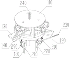
Fig. 1 is a schematic structural view of a robot gripper device for processing electrical products according to the present invention.
Fig. 2 is a schematic structural diagram of a lower portion of the robot gripper device for processing electrical products according to the present invention.
Fig. 3 is a schematic view of a connection structure of a sun gear and a driving gear according to the present invention.
Fig. 4 is a schematic view of the upper seat structure according to the present invention.
Fig. 5 is a schematic view of the lower seat structure according to the present invention.
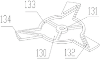
Fig. 6 is a schematic view of the structure of the driving plate according to the present invention.
Fig. 7 is a schematic view of a dovetail block structure according to the present invention.
Fig. 8 is a schematic view of the driving gear structure according to the present invention.
Fig. 9 is a schematic view of a driven gear structure according to the present invention.
Fig. 10 is a schematic view of the structure of the transmission disc of the present invention.
Fig. 11 is a schematic view of a jaw structure according to the present invention.
Fig. 12 is a schematic view of the nut seat structure according to the present invention.
Fig. 13 is a schematic structural view of a lead screw base according to the present invention.
Detailed Description
The invention is explained in more detail below with reference to the figures and examples:
a robot paw hand device for processing electric products comprises an upper seat 110, a lower seat 120, a driving plate 130, a dovetail block 140, a driving gear 150, a driven gear 160, a driving disc 170, a clamping jaw 180, a nut seat 190 and a screw seat 210, wherein a center hole 111 is formed in the middle of the upper seat 110, a motor plate 112 is arranged on one side of the center hole 111, three gear shaft holes 113 are uniformly distributed in the outer side of the center hole 111, a lower seat shaft 121 is arranged in the middle of the lower seat 120, three waist grooves 122 are uniformly distributed in the outer side of the lower seat shaft 121, a dovetail groove 123 is respectively arranged on the lower portion of each waist groove 122, three supporting columns 124 are uniformly distributed in the outer side of the lower seat 120, a side plate 125 is arranged in the outer side of the side plate 125, a screw seat hole 126 is arranged in the middle of the driving plate 130, three avoiding grooves 133 are uniformly distributed in the outer side of the driving plate hole 131, three driving grooves 132 are distributed on the outer side of the driving plate 130, a nut seat hole 134 is formed in the outer side of one driving groove 132, a driving rod 141 is arranged on one side of the dovetail block 140, a dovetail block hole 142 is formed in the other side of the dovetail block 140, an ear plate 143 is arranged on the outer side of the dovetail block hole 142, an ear plate lower hole 144 is formed in the lower portion of the side surface of the ear plate 143, an ear plate upper hole 145 is formed in the upper portion of the ear plate lower hole 144, three supporting columns 124 are fixedly connected to the lower portion of the upper seat 110, the driving plate hole 131 is rotatably connected with the lower seat shaft 121, the driving plate 130 rotates around the lower seat shaft 121, one dovetail block 140 is arranged on the inner side of each dovetail groove 123, each dovetail block 140 is slidably connected with the corresponding dovetail groove 123, each dovetail block 140 slides in the corresponding dovetail groove 123, and each driving groove 132 is slidably connected with the corresponding driving rod 141. When the invention is used, the clamping radius of the invention is adjusted according to the radius of the clamped material, firstly, the screw seat 210 is rotated, the screw seat 210 rotates to drive the drive plate 130 to rotate through the nut seat 190, when the drive plate 130 rotates, the three dovetail blocks 140 are driven by the drive plate 130 to slide along the dovetail grooves 123, the radius of the circle where the three dovetail blocks 140 are positioned is increased or reduced, when the dovetail blocks 140 move, the driven gear 160 and the clamping jaws 180 are driven to move simultaneously, when the driven gear 160 moves, the axial lines of the driving gear 150, the driven gear 160 and the intermediate drive plate 170 are offset, the radius of the circle where the three clamping jaws 180 are positioned is synchronously increased or reduced, thereby the clamping radius of the invention is changed, and secondly, when the machine 240 is normally operated, the motor 240 rotates to drive the central gear 270 to rotate, the central gear 270 rotates to simultaneously drive the three driving gears 150 to rotate, the driving gears 150 rotate to drive the respective driving disks 170 to rotate, each driving disk 170 drives the respective driven gear 160 to rotate, the driven gear 160 rotates to drive the respective worm 250 to rotate, each worm 250 rotates to drive the respective worm gear 260 to rotate, each worm gear 260 rotates to drive the respective second connecting rod 290 to rotate through the respective shaft 280, each second connecting rod 290 rotates to drive the respective clamping jaw 180 to synchronously move towards the center of the invention in parallel through the corresponding first connecting rod 220 until the material is grabbed, then the robot drives the invention and the material to a set position, the motor 240 is reversely started, and the material is put down.
The driving gear 150 has a driving gear shaft 152 at the middle of the upper portion thereof, the driving gear 150 has a driving gear groove 151 at the lower portion thereof, the driven gear 160 has a driven gear shaft 162 at the middle of the lower portion thereof, the driven gear shaft 162 has a worm shaft 163 at the lower portion thereof, the driving plate 170 has an upper dog 171 at the upper portion thereof, the driving plate 170 has a lower dog 172 at the lower portion thereof, the central gear 270 passes through the central hole 111 from the lower portion thereof, the central gear 270 rotates in the central hole 111, the motor 240 is fixedly connected to the motor plate 112 at the side thereof, the motor 240 output shaft is fixedly connected to the central gear 270, one driving gear 150 is disposed in each gear shaft hole 113, each driving gear 150 passes through the gear shaft hole 113 from the lower portion thereof, each driving gear 150 rotates in the gear shaft hole 113, the central gear 270 simultaneously meshes with the three driving gears 150, one driven gear 160 is disposed in each dovetail block 140, each driven gear shaft 162 passes through the corresponding dovetail groove 133, the corresponding dovetail groove 122, the corresponding dovetail block 142, each driven gear shaft 162 is rotatably connected to the driving dog 160, and the driving gear groove 172 is slidably connected to the corresponding dovetail block 160, and the driven gear shaft 171 is slidably connected to the driving gear groove 172.
The upper portion of the nut seat 190 is provided with a nut seat shaft 191, the side surface of the nut seat 190 is provided with a threaded hole 192, the lower portion of the screw seat 210 is provided with a screw seat shaft 211, the side surface of the screw seat 210 is provided with a screw seat hole 212, the nut seat shaft 191 is rotatably connected with the nut seat hole 134, the nut seat 190 rotates in the nut seat hole 134, the screw seat shaft 211 is rotatably connected with the screw seat hole 126, the screw seat 210 rotates in the screw seat hole 126, the screw 230 is in threaded connection with the threaded hole 192, and the middle shaft of the screw 230 is rotatably connected with the screw seat hole 212.
The invention can adapt to the change of product specifications, the clamping radius of a claw hand is adjusted, the screw rod seat 210 is rotated, the screw rod seat 210 rotates to drive the drive plate 130 to rotate through the nut seat 190, when the drive plate 130 rotates, the three dovetail blocks 140 are driven by the drive plate 130 to slide along the dovetail grooves 123, the radius of a circle where the three dovetail blocks 140 are located is increased or reduced, when the dovetail blocks 140 move, the driven gears 160 and the clamping jaws 180 are driven to move simultaneously, the driving gears 150 and the drive plate 170 are respectively connected with the driven gears 160 and the drive plate 170 in a sliding manner, when the driven gears 160 move, the axes of the driving gears 150 and the driven gears 160 and the axis of the drive plate 170 in the middle are deviated, the diameter of the circle where the three driving gears 150 are located is fixed, and the diameter of the circle where the three driven gears 160 are located floats, so that the rotation of the three driving gears 150 can be transmitted to the corresponding driven gears 160 through the drive plate 170, the diameters of the circles where the three clamping jaws 180 can be adjusted, the three clamping jaws 180 can be synchronously clamped through the rotation of the driving gears 150, the centering and the clamping of materials can be ensured, the accurate stress position, the deviation can be prevented, the balanced clamping of the materials can be prevented, the balanced falling of the materials can be prevented, and the materials can be prevented from falling can be prevented, and prevented from falling can be synchronously clamped stably.
The clamping jaw 180 is provided with a clamping jaw first hole 181 on the side upper portion, a clamping jaw second hole 182 on the side lower portion, a worm 250 is fixedly connected to the outer side of each worm shaft 163, a shaft 280 is rotatably connected to each ear plate upper hole 145, each shaft 280 rotates in the corresponding ear plate upper hole 145, a worm wheel 260 is fixedly connected to the middle of each shaft 280, each worm wheel 260 is meshed with the corresponding worm 250, a second connecting rod 290 is fixedly connected to two sides of each shaft 280, another shaft 280 is rotatably connected to each ear plate lower hole 144, each shaft 280 rotates in the corresponding ear plate lower hole 144, a first connecting rod 220 is fixedly connected to each shaft 280, the other sides of the two second connecting rods 290 at the same position are respectively hinged to the corresponding clamping jaw first holes 181, and the other sides of the two first connecting rods 220 at the same position are respectively hinged to the corresponding clamping jaw second holes 182. When the material clamping device is used, the clamping radius of the material clamping device is adjusted according to the radius of a clamped material, when the material clamping device is adjusted, the screw rod seat is rotated, the screw rod seat drives the driving plate to rotate through the nut seat, when the driving plate rotates, the three dovetail blocks are driven by the driving plate to slide along the dovetail grooves, the radius of a circle where the three dovetail blocks are located is increased or decreased, when the dovetail blocks move, the driven gear and the clamping jaws are driven to move simultaneously, when the driven gear moves, the axes of the driving gear and the driven gear and the axis of a middle driving disc deviate, the radius of the circle where the three clamping jaws are located is increased or decreased synchronously, so that the clamping radius of the material clamping device is changed, when the motor works normally, the motor is started to rotate to drive the central gear, the central gear rotates to drive the three driving gears to rotate simultaneously, the driving gear rotates to drive the respective driving discs to rotate, each driving disc drives the respective driven gear to rotate, each worm rotates to drive the respective turbine, each turbine rotates to drive the respective second connecting rod to drive the respective connecting rod to rotate through the corresponding first connecting rod, and the second connecting rod rotates until the clamping jaws are driven by the motor and are driven by the motor to move in parallel to the material clamping jaws.
An operation method of a robot gripper device for processing electrical products comprises the following steps: the first step, according to the radius of the material to be clamped, the clamping radius of the invention is adjusted, during adjustment, the screw rod seat 210 is rotated, the radius of the circle where the three clamping jaws 180 are located is synchronously increased or decreased, thereby changing the clamping radius of the invention, the second step, during normal operation, the motor 240 is started, the three clamping jaws 180 synchronously move towards the center of the invention until the material is grabbed, then the robot drives the invention and the material to the set position, the motor 240 is reversely started, and the material is put down.
Claims (5)
1. The robot claw hand device is characterized by comprising an upper seat, a lower seat, a drive plate, dovetail blocks, a driving gear, a driven gear, a transmission disc, a clamping jaw, a nut seat and a lead screw seat, wherein a center hole is formed in the middle of the upper seat, a motor plate is arranged on one side of the center hole, three gear shaft holes are uniformly distributed in the outer side of the center hole, a lower seat shaft is arranged in the middle of the lower seat, three kidney slots are uniformly distributed in the outer side of the lower seat shaft, a dovetail groove is formed in the lower part of each kidney slot, three supporting columns are uniformly distributed in the outer side of the lower seat, a side plate is arranged on the outer side of the lower seat, a lead screw seat hole is formed in the outer side of the side plate, a drive plate hole is formed in the middle of the drive plate, three avoiding grooves are uniformly distributed in the outer side of the drive plate, three drive grooves are distributed in the outer side of the drive plate, a nut seat hole is formed in the outer side of one of the dovetail block, a dovetail block is provided with a dovetail block hole in the other side of the dovetail block, a lug plate lower hole is provided with a lug plate lower hole, a lug plate upper hole in the upper part of the dovetail plate, the upper seat hole is fixedly connected with three supporting columns, the drive plate hole, the dovetail groove is connected with each dovetail groove, and a dovetail groove corresponding sliding connection with each dovetail block, and each dovetail block is connected with each dovetail block in a sliding way.
2. The device of claim 1, wherein the driving gear shaft is provided in the middle of the upper portion of the driving gear, the driving gear slot is provided in the lower portion of the driving gear, the driven gear slot is provided in the middle of the upper portion of the driven gear, the driven gear shaft is provided in the middle of the lower portion of the driven gear, the worm shaft is provided in the lower portion of the driven gear shaft, the upper fixture block is provided in the upper portion of the driving plate, the lower fixture block is provided in the lower portion of the driving plate, the central gear shaft passes through the central hole from the lower portion, the central gear shaft is rotatably connected to the central hole, the motor side is fixedly connected to the motor plate side, the motor output shaft is fixedly connected to the central gear shaft, a driving gear is provided in each gear shaft hole, each driving gear shaft passes through a corresponding gear shaft hole from the lower portion, each driving gear shaft rotates in the gear shaft hole, the central gear is simultaneously engaged with three driving gears, a driven gear is provided in each dovetail block, each driven gear shaft passes through a corresponding relief slot, a corresponding dovetail block hole, and the upper fixture block is slidably connected to the driving gear slot.
3. The gripper device of claim 2, wherein the nut holder has a nut holder shaft at an upper portion thereof, a threaded hole at a side surface thereof, a screw holder shaft at a lower portion thereof, a screw holder hole at a side surface thereof, the nut holder shaft rotatably coupled to the nut holder hole, the nut holder is rotatable in the nut holder hole, the screw holder shaft rotatably coupled to the screw holder hole, the screw holder is rotatable in the screw holder hole, the screw is threadedly coupled to the threaded hole, and the screw intermediate shaft is rotatably coupled to the screw holder hole.
4. The robot gripper device for processing the electrical products as claimed in claim 3, wherein the upper part of the side surface of the gripper jaw is provided with a first gripper jaw hole, the lower part of the side surface of the gripper jaw is provided with a second gripper jaw hole, a worm is fixedly connected to the outer side of each worm shaft, a shaft is rotatably connected to each upper hole of the lug plate, each shaft rotates in the corresponding upper hole of the lug plate, a worm wheel is fixedly connected to the middle of each shaft, each worm wheel is meshed with the corresponding worm, a second connecting rod is fixedly connected to two sides of each shaft, another shaft is rotatably connected to each lower hole of the lug plate, each shaft rotates in the corresponding lower hole of the lug plate, a first connecting rod is fixedly connected to each two sides of each shaft, the other sides of the two second connecting rods at the same position are respectively hinged to the corresponding first gripper jaw holes, and the other sides of the two first connecting rods at the same position are respectively hinged to the corresponding second gripper jaw holes.
5. The operation method of the robot gripper device for processing the electric products as claimed in claim 4, characterized by comprising the following steps: firstly, adjusting the clamping radius of the robot gripper device according to the radius of a clamped material, and rotating a screw rod seat during adjustment to synchronously increase or reduce the radius of a circle where three clamping jaws are located, so that the clamping radius of the robot gripper device is changed; and secondly, when the robot works normally, the motor is started, the three clamping jaws synchronously move towards the center of the robot until the material is grabbed, then the robot drives the robot and the material to a set position, the motor is reversely started, and the material is put down.
Priority Applications (1)
| Application Number | Priority Date | Filing Date | Title |
|---|---|---|---|
| CN202211314799.2A CN115592698A (en) | 2022-10-26 | 2022-10-26 | Robot claw device for processing electrical products and operation method |
Applications Claiming Priority (1)
| Application Number | Priority Date | Filing Date | Title |
|---|---|---|---|
| CN202211314799.2A CN115592698A (en) | 2022-10-26 | 2022-10-26 | Robot claw device for processing electrical products and operation method |
Publications (1)
| Publication Number | Publication Date |
|---|---|
| CN115592698A true CN115592698A (en) | 2023-01-13 |
Family
ID=84848022
Family Applications (1)
| Application Number | Title | Priority Date | Filing Date |
|---|---|---|---|
| CN202211314799.2A Withdrawn CN115592698A (en) | 2022-10-26 | 2022-10-26 | Robot claw device for processing electrical products and operation method |
Country Status (1)
| Country | Link |
|---|---|
| CN (1) | CN115592698A (en) |
Cited By (1)
| Publication number | Priority date | Publication date | Assignee | Title |
|---|---|---|---|---|
| CN117733438A (en) * | 2023-12-29 | 2024-03-22 | 北京市政建设集团有限责任公司 | Mobile welding robot |
-
2022
- 2022-10-26 CN CN202211314799.2A patent/CN115592698A/en not_active Withdrawn
Cited By (1)
| Publication number | Priority date | Publication date | Assignee | Title |
|---|---|---|---|---|
| CN117733438A (en) * | 2023-12-29 | 2024-03-22 | 北京市政建设集团有限责任公司 | Mobile welding robot |
Similar Documents
| Publication | Publication Date | Title |
|---|---|---|
| CN110976955B (en) | Intelligent control device for machining size of thrust cylindrical roller bearing | |
| CN210099385U (en) | A pair of linkage self-centering chuck for pipe cutting machine | |
| CN103447823B (en) | A kind of numerical-control processing method of automobile axle shaft | |
| CN114131383A (en) | Double-end digit control machine tool of processing axle piece | |
| CN205414453U (en) | Lathe work special fixture of accurate graduation | |
| CN205571416U (en) | Planetary lathe of not being in mood for of machining radius adjustable | |
| CN201744877U (en) | Automatic positioning frame | |
| CN216029401U (en) | A rotary clamping device for a CNC machining center | |
| WO2017167134A1 (en) | Planetary centerless lathe having adjustable machining radius | |
| CN219152600U (en) | Butterfly valve processing hydraulic clamp with size adjusting function | |
| CN205414455U (en) | Lathe work special fixture | |
| CN214418228U (en) | A workpiece clamping device for CNC machine tools | |
| CN113618327A (en) | A high-precision stepping motor-driven chuck device for automatic welding | |
| CN219598294U (en) | Positioning fixture for machining high-precision gear | |
| CN220881427U (en) | Hydraulic cushion block punching and positioning device | |
| CN111687489A (en) | Nylon pin continuous processing machine | |
| CN223419387U (en) | Large slewing bearing processing fixture | |
| CN221111851U (en) | Pneumatic clamping gripping apparatus | |
| CN223849092U (en) | A wheel hub processing table | |
| CN214445138U (en) | Shaft sleeve end face machining tool | |
| CN223733916U (en) | Drilling jig device with adjustable drilling position | |
| CN223098065U (en) | A drilling mechanism for wheel hub processing | |
| CN206967171U (en) | Disc type multi-station pen point process equipment | |
| CN223762184U (en) | Multi-specification-adaptive machine tool clamping jaw | |
| CN222289668U (en) | Optical component rack processing equipment |
Legal Events
| Date | Code | Title | Description |
|---|---|---|---|
| PB01 | Publication | ||
| PB01 | Publication | ||
| SE01 | Entry into force of request for substantive examination | ||
| SE01 | Entry into force of request for substantive examination | ||
| WW01 | Invention patent application withdrawn after publication | ||
| WW01 | Invention patent application withdrawn after publication |
Application publication date: 20230113 |