CN115592205A - Automatic fixed-length cutting equipment for plate spring processing - Google Patents
Automatic fixed-length cutting equipment for plate spring processing Download PDFInfo
- Publication number
- CN115592205A CN115592205A CN202211224662.8A CN202211224662A CN115592205A CN 115592205 A CN115592205 A CN 115592205A CN 202211224662 A CN202211224662 A CN 202211224662A CN 115592205 A CN115592205 A CN 115592205A
- Authority
- CN
- China
- Prior art keywords
- plate
- leaf spring
- roller
- slider
- fixed
- Prior art date
- Legal status (The legal status is an assumption and is not a legal conclusion. Google has not performed a legal analysis and makes no representation as to the accuracy of the status listed.)
- Granted
Links
- 238000012545 processing Methods 0.000 title claims abstract description 21
- 230000005540 biological transmission Effects 0.000 claims description 64
- 238000003780 insertion Methods 0.000 claims description 17
- 230000037431 insertion Effects 0.000 claims description 17
- 238000013519 translation Methods 0.000 claims description 14
- 238000001125 extrusion Methods 0.000 claims description 13
- 230000006835 compression Effects 0.000 claims description 12
- 238000007906 compression Methods 0.000 claims description 12
- 238000007789 sealing Methods 0.000 claims description 4
- 238000005259 measurement Methods 0.000 abstract description 16
- 238000000691 measurement method Methods 0.000 abstract description 3
- 238000003672 processing method Methods 0.000 abstract description 3
- 238000005096 rolling process Methods 0.000 abstract description 3
- 238000010586 diagram Methods 0.000 description 6
- 238000000034 method Methods 0.000 description 3
- 230000000903 blocking effect Effects 0.000 description 2
- 230000005489 elastic deformation Effects 0.000 description 2
- 238000009434 installation Methods 0.000 description 2
- 238000012986 modification Methods 0.000 description 2
- 230000004048 modification Effects 0.000 description 2
- 238000013459 approach Methods 0.000 description 1
- 230000004888 barrier function Effects 0.000 description 1
- 230000009286 beneficial effect Effects 0.000 description 1
- 238000004891 communication Methods 0.000 description 1
- 238000010276 construction Methods 0.000 description 1
- 238000003698 laser cutting Methods 0.000 description 1
- 230000007246 mechanism Effects 0.000 description 1
- 230000000750 progressive effect Effects 0.000 description 1
Images


Classifications
-
- B—PERFORMING OPERATIONS; TRANSPORTING
- B23—MACHINE TOOLS; METAL-WORKING NOT OTHERWISE PROVIDED FOR
- B23D—PLANING; SLOTTING; SHEARING; BROACHING; SAWING; FILING; SCRAPING; LIKE OPERATIONS FOR WORKING METAL BY REMOVING MATERIAL, NOT OTHERWISE PROVIDED FOR
- B23D79/00—Methods, machines, or devices not covered elsewhere, for working metal by removal of material
-
- B—PERFORMING OPERATIONS; TRANSPORTING
- B23—MACHINE TOOLS; METAL-WORKING NOT OTHERWISE PROVIDED FOR
- B23Q—DETAILS, COMPONENTS, OR ACCESSORIES FOR MACHINE TOOLS, e.g. ARRANGEMENTS FOR COPYING OR CONTROLLING; MACHINE TOOLS IN GENERAL CHARACTERISED BY THE CONSTRUCTION OF PARTICULAR DETAILS OR COMPONENTS; COMBINATIONS OR ASSOCIATIONS OF METAL-WORKING MACHINES, NOT DIRECTED TO A PARTICULAR RESULT
- B23Q17/00—Arrangements for observing, indicating or measuring on machine tools
- B23Q17/20—Arrangements for observing, indicating or measuring on machine tools for indicating or measuring workpiece characteristics, e.g. contour, dimension, hardness
-
- B—PERFORMING OPERATIONS; TRANSPORTING
- B23—MACHINE TOOLS; METAL-WORKING NOT OTHERWISE PROVIDED FOR
- B23Q—DETAILS, COMPONENTS, OR ACCESSORIES FOR MACHINE TOOLS, e.g. ARRANGEMENTS FOR COPYING OR CONTROLLING; MACHINE TOOLS IN GENERAL CHARACTERISED BY THE CONSTRUCTION OF PARTICULAR DETAILS OR COMPONENTS; COMBINATIONS OR ASSOCIATIONS OF METAL-WORKING MACHINES, NOT DIRECTED TO A PARTICULAR RESULT
- B23Q3/00—Devices holding, supporting, or positioning work or tools, of a kind normally removable from the machine
- B23Q3/02—Devices holding, supporting, or positioning work or tools, of a kind normally removable from the machine for mounting on a work-table, tool-slide, or analogous part
- B23Q3/06—Work-clamping means
-
- Y—GENERAL TAGGING OF NEW TECHNOLOGICAL DEVELOPMENTS; GENERAL TAGGING OF CROSS-SECTIONAL TECHNOLOGIES SPANNING OVER SEVERAL SECTIONS OF THE IPC; TECHNICAL SUBJECTS COVERED BY FORMER USPC CROSS-REFERENCE ART COLLECTIONS [XRACs] AND DIGESTS
- Y02—TECHNOLOGIES OR APPLICATIONS FOR MITIGATION OR ADAPTATION AGAINST CLIMATE CHANGE
- Y02P—CLIMATE CHANGE MITIGATION TECHNOLOGIES IN THE PRODUCTION OR PROCESSING OF GOODS
- Y02P70/00—Climate change mitigation technologies in the production process for final industrial or consumer products
- Y02P70/10—Greenhouse gas [GHG] capture, material saving, heat recovery or other energy efficient measures, e.g. motor control, characterised by manufacturing processes, e.g. for rolling metal or metal working
Landscapes
- Engineering & Computer Science (AREA)
- Mechanical Engineering (AREA)
- Physics & Mathematics (AREA)
- Optics & Photonics (AREA)
- Sawing (AREA)
Abstract
本发明涉及组合加工设备的技术领域,特别是涉及一种板簧加工用自动定长切断设备,包括操作台、板簧本体和第一弓形板,操作台顶部左右两侧均设置有夹持组,夹持组用于对板簧本体进行固定,夹持组由输送辊和挤压辊组成,输送辊转动安装在操作台上,挤压辊位于操作台上,并且挤压辊与输送辊接近,挤压辊用于将板簧本体挤压固定在输送辊上;通过采用自动定长切断的方式对板簧本体进行加工处理,可有效简化加工方式,实现自动化加工,节省人工操作的时间和人力,提高工作效率,同时通过滚动测量的方式可实现对板簧本体弧形长度的直接测量,有效简化测量方式,提高测量精度。
The invention relates to the technical field of combined processing equipment, in particular to an automatic fixed-length cutting equipment for leaf spring processing, which includes an operating table, a leaf spring body and a first bow-shaped plate, and clamping groups are arranged on the left and right sides of the top of the operating table , the clamping group is used to fix the leaf spring body. The clamping group is composed of a conveying roller and a squeeze roller. The conveying roller is rotatably installed on the operating table, and the squeezing roller is located on the operating table, and the squeezing roller is close to the conveying roller. , the squeeze roller is used to squeeze and fix the leaf spring body on the conveying roller; the leaf spring body is processed by automatic fixed-length cutting, which can effectively simplify the processing method, realize automatic processing, and save the time and cost of manual operation Manpower is used to improve work efficiency, and at the same time, the direct measurement of the arc length of the leaf spring body can be realized by means of rolling measurement, which effectively simplifies the measurement method and improves the measurement accuracy.
Description
技术领域technical field
本发明涉及组合加工设备的技术领域,特别是涉及一种板簧加工用自动定长切断设备。The invention relates to the technical field of combined processing equipment, in particular to an automatic fixed-length cutting equipment for leaf spring processing.
背景技术Background technique
众所周知,板簧一种具有较强弹性的弧形板状结构,其主要作为汽车上车厢与桥架之间的连接装置,板簧能够为车厢提供支撑和缓冲作用,板簧在加工后,为使其满足安装要求,一般需要将其切断成规定长度,传统的切断设备在使用时,需要人工配合进行板簧的测量工作,之后通过切断设备对测量完成的位置进行切断处理,然而采用此种方式时,由于板簧的形状为弧形,工人通过测量尺进行测量的准确度较差,导致板簧的切断精度较低,同时人机配合测量切断的方式较为繁琐,无法实现板簧的自动化定长切断工作,并且消耗人力较多,工作效率较低。As we all know, the leaf spring is an arc-shaped plate structure with strong elasticity. It is mainly used as a connecting device between the upper compartment of the car and the bridge frame. The leaf spring can provide support and buffer for the compartment. It meets the installation requirements, and generally needs to be cut to a specified length. When using traditional cutting equipment, it is necessary to manually cooperate with the measurement of the leaf spring, and then cut off the measured position through the cutting equipment. However, this method At the same time, because the shape of the leaf spring is arc-shaped, the accuracy of the workers' measurement through the measuring ruler is poor, resulting in low cutting accuracy of the leaf spring. Long cutting work, and more manpower consumption, lower work efficiency.
发明内容Contents of the invention
为解决上述技术问题,本发明提供一种板簧加工用自动定长切断设备。In order to solve the above technical problems, the present invention provides an automatic fixed-length cutting device for leaf spring processing.
为了达到上述目的,本发明所采用的技术方案是:In order to achieve the above object, the technical scheme adopted in the present invention is:
板簧加工用自动定长切断设备,包括操作台、板簧本体和第一弓形板,操作台顶部左右两侧均设置有夹持组,夹持组用于对板簧本体进行固定,夹持组由输送辊和挤压辊组成,输送辊转动安装在操作台上,挤压辊位于操作台上,并且挤压辊与输送辊接近,挤压辊用于将板簧本体挤压固定在输送辊上,板簧本体穿过夹持组内的输送辊和挤压辊,根据挤压辊转动圈数、转动角度等参数测量板簧本体在输送辊和挤压辊之间输送长度;Automatic fixed-length cutting equipment for leaf spring processing, including the operating table, leaf spring body and the first bow-shaped plate. There are clamping groups on the left and right sides of the top of the operating table. The clamping groups are used to fix the leaf spring body. The set consists of a conveying roller and a squeeze roller. The conveying roller is rotatably installed on the console, and the squeeze roller is located on the console, and the squeeze roller is close to the conveying roller. The squeeze roller is used to squeeze and fix the leaf spring body on the conveyor On the roller, the leaf spring body passes through the conveying roller and squeeze roller in the clamping group, and the conveying length of the leaf spring body between the conveying roller and the squeeze roller is measured according to the parameters such as the number of turns of the squeeze roller and the rotation angle;
第一弓形板位于操作台上方,第一弓形板内壁左右两侧分别设置有激光发生器和挡光板。The first bow-shaped board is located above the operating table, and the left and right sides of the inner wall of the first bow-shaped board are respectively provided with a laser generator and a light shield.
进一步地,所述操作台上倾斜开设有两个第一导向槽,第一导向槽的长度方向沿板簧本体的径向方向,第一导向槽内滑动设置有第一滑块,挤压辊转动安装在第一滑块上,第一滑块的底部安装有第一连接板,操作台的底部安装有第一导轨,第一导轨上滑动设置有平移板,第一连接板的外端滑动安装在平移板上,平移板侧壁上安装有气缸,气缸的固定端安装在操作台底部。Further, two first guide grooves are obliquely opened on the operating platform, the length direction of the first guide grooves is along the radial direction of the leaf spring body, a first slider is slidably arranged in the first guide grooves, and the squeeze roller Rotationally installed on the first slider, the bottom of the first slider is installed with the first connecting plate, the bottom of the operating table is installed with the first guide rail, the first guide rail is slidingly provided with a translation plate, and the outer end of the first connecting plate slides Installed on the translation plate, the side wall of the translation plate is equipped with a cylinder, and the fixed end of the cylinder is installed at the bottom of the console.
进一步地,两个第一滑块中的一个第一滑块底部安装有输送电机,输送电机的输出端与第一滑块上的挤压辊传动连接,另一个第一滑块底部安装有连接轴,连接轴与第一滑块上的挤压辊传动连接,连接轴底部安装有锥形传动盘,锥形传动盘上传动设置有传动杆,传动杆倾斜,传动杆的两端均安装有接触开关,操作台的底部安装有两个挡板,两个挡板位于传动杆的左右两侧;Further, a conveying motor is installed at the bottom of one of the two first sliders, and the output end of the conveying motor is connected to the extrusion roller on the first slider, and a connection is installed at the bottom of the other first slider. shaft, the connecting shaft is connected with the extrusion roller on the first slider, the bottom of the connecting shaft is equipped with a conical transmission disc, and a transmission rod is installed on the conical transmission disc, the transmission rod is inclined, and the two ends of the transmission rod are installed with Contact switch, two baffles are installed on the bottom of the console, and the two baffles are located on the left and right sides of the transmission rod;
其中,传动杆位于输送辊和挤压辊之间连线的中心点上,并且传动杆与连线垂直。Wherein, the transmission rod is located at the central point of the line between the conveying roller and the squeezing roller, and the transmission rod is perpendicular to the connection line.
进一步地,所述操作台底部安装有第二导轨,第二导轨与传动杆平行,第二导轨左右两侧均滑动设置有第二滑块,第二滑块上倾斜转动安装有推拉臂,两个推拉臂的倾斜方向相反,推拉臂的外端设置有第二连接板,第二连接板与推拉臂转动连接,第二连接板固定在锥形传动盘上的第一滑块底部;Further, a second guide rail is installed on the bottom of the operating table, the second guide rail is parallel to the transmission rod, and the left and right sides of the second guide rail are slidingly provided with second sliders, and a push-pull arm is installed on the second slider for tilting and rotating. The inclination direction of the two push-pull arms is opposite, the outer end of the push-pull arm is provided with a second connecting plate, the second connecting plate is rotatably connected with the push-pull arm, and the second connecting plate is fixed on the bottom of the first slider on the tapered transmission disc;
第二连接板中部转动安装有连接柱,连接柱底部固定有导向框,导向框内滑动设置有第三滑块,第三滑块底部安装有拉簧,拉簧底部固定在导向框上,传动杆穿过两个第三滑块并滑动连接,连接轴外壁上安装有扭簧,扭簧的外端固定在第一连接板上。The middle part of the second connecting plate is rotatably installed with a connecting column, and the bottom of the connecting column is fixed with a guide frame, and a third slider is slid inside the guide frame, and a tension spring is installed at the bottom of the third slider, and the bottom of the tension spring is fixed on the guide frame. The rod passes through the two third sliders and is slidably connected, a torsion spring is installed on the outer wall of the connecting shaft, and the outer end of the torsion spring is fixed on the first connecting plate.
进一步地,还包括第二弓形板,第二弓形板扣设在第一弓形板的外侧,第二弓形板的外壁上安装有外板,外板的底部固定在操作台上;Further, it also includes a second bow-shaped plate, the second bow-shaped plate is fastened on the outside of the first bow-shaped plate, an outer plate is installed on the outer wall of the second bow-shaped plate, and the bottom of the outer plate is fixed on the operating table;
第二弓形板内部前后两侧的每个侧壁上均开设有两个第二导向槽,两个第二导向槽倾斜并且倾斜方向相反,第二导向槽内滑动设置有第四滑块,第四滑块的外端安装有弧形夹板,弧形夹板保持竖向状态;Two second guide grooves are provided on each side wall of the front and rear sides of the second arcuate plate. The two second guide grooves are inclined and the inclination directions are opposite. A fourth slider is slid in the second guide groove. The outer ends of the four sliders are equipped with arc-shaped splints, and the arc-shaped splints maintain a vertical state;
所述第二弓形板内设置有两个插杆,插杆的两端穿过两个弧形夹板并滑动连接,第一弓形板内部左右两侧的每个侧壁上均开设有两个压簧,插杆的外端滑动安装在第三导向槽内,弧形夹板外壁与第一弓形板内壁之间的插杆上套设有压簧,压簧的一端固定在弧形夹板上,压簧的另一端固定在插杆外壁上。Two inserting rods are arranged inside the second bow-shaped plate, and the two ends of the inserting rods pass through the two arc-shaped splints and are slidably connected. The outer end of the insertion rod is slidably installed in the third guide groove, and the insertion rod between the outer wall of the arc-shaped splint and the inner wall of the first bow-shaped plate is sleeved with a compression spring, and one end of the compression spring is fixed on the arc-shaped splint. The other end of spring is fixed on the plunger outer wall.
进一步地,还包括主电机,主电机位于第二弓形板上方,主电机外壁上安装有直角架,直角架固定在第二弓形板上,主电机输出端安装有螺纹杆,第一弓形板顶部安装有螺纹管,螺纹杆穿过第二弓形板并螺装入螺纹管内,螺纹杆与第二弓形板转动连接。Further, it also includes a main motor, the main motor is located above the second bow-shaped plate, a right-angle frame is installed on the outer wall of the main motor, the right-angle frame is fixed on the second bow-shaped plate, a threaded rod is installed at the output end of the main motor, and the top of the first bow-shaped plate A threaded pipe is installed, a threaded rod passes through the second arched plate and is screwed into the threaded pipe, and the threaded rod is rotatably connected with the second arched plate.
进一步地,第一弓形板的外壁上安装有第三连接板,第三连接板的端部安装有第五滑块,第五滑块滑动安装在第二弓形板上。Further, a third connecting plate is installed on the outer wall of the first arched plate, a fifth slider is installed on the end of the third connecting plate, and the fifth sliding block is slidably installed on the second arched plate.
进一步地,所述输送辊顶部安装有封盘。Further, a sealing disk is installed on the top of the conveying roller.
与现有技术相比本发明的有益效果为:通过采用自动定长切断的方式对板簧本体进行加工处理,可有效简化加工方式,实现自动化加工,节省人工操作的时间和人力,提高工作效率,同时通过滚动测量的方式可实现对板簧本体弧形长度的直接测量,有效简化测量方式,提高测量精度。Compared with the prior art, the beneficial effect of the present invention is: the leaf spring body can be processed by adopting automatic fixed-length cutting, which can effectively simplify the processing method, realize automatic processing, save the time and manpower of manual operation, and improve work efficiency At the same time, the direct measurement of the arc length of the leaf spring body can be realized by means of rolling measurement, which effectively simplifies the measurement method and improves the measurement accuracy.
附图说明Description of drawings
为了更清楚地说明本发明实施例或现有技术中的技术方案,下面将对实施例或现有技术描述中所需要使用的附图作简单地介绍,显而易见地,下面描述中的附图仅仅是本发明中记载的一些实施例,对于本领域普通技术人员来讲,在不付出创造性劳动的前提下,还可以根据这些附图获得其他的附图。In order to more clearly illustrate the technical solutions in the embodiments of the present invention or the prior art, the following will briefly introduce the drawings that need to be used in the description of the embodiments or the prior art. Obviously, the accompanying drawings in the following description are only These are some embodiments described in the present invention. Those skilled in the art can also obtain other drawings based on these drawings without creative work.
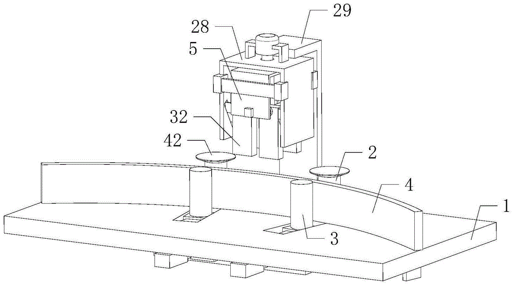
图1是本发明的结构示意图;Fig. 1 is a structural representation of the present invention;
图2是图1中第二弓形板放大结构示意图;Fig. 2 is a schematic diagram of the enlarged structure of the second arcuate plate in Fig. 1;
图3是图2中第二弓形板右视剖视结构示意图;Fig. 3 is a right view sectional structure schematic diagram of the second arcuate plate in Fig. 2;
图4是图3中第一弓形板放大结构示意图;Fig. 4 is a schematic diagram of the enlarged structure of the first arcuate plate in Fig. 3;
图5是图1中操作台仰视结构示意图;Fig. 5 is a schematic view of the structure of the operating platform in Fig. 1;
图6是图5中A处局部放大结构示意图;Fig. 6 is a schematic diagram of a partially enlarged structure at A in Fig. 5;
图7是图6中第一连接板前侧结构示意图;Fig. 7 is a schematic diagram of the front side structure of the first connecting plate in Fig. 6;
图8是图6中锥形传动盘俯视结构示意图;Fig. 8 is a top view structural diagram of the conical drive disc in Fig. 6;
附图中标记:1、操作台;2、输送辊;3、挤压辊;4、板簧本体;5、第一弓形板;6、激光发生器;7、挡光板;8、第一导向槽;9、第一滑块;10、第一连接板;11、第一导轨;12、平移板;13、气缸;14、连接轴;15、锥形传动盘;16、传动杆;17、接触开关;18、挡板;19、第二导轨;20、第二滑块;21、推拉臂;22、第二连接板;23、连接柱;24、导向框;25、第三滑块;26、拉簧;27、扭簧;28、第二弓形板;29、外板;30、第二导向槽;31、第四滑块;32、弧形夹板;33、插杆;34、第三导向槽;35、压簧;36、主电机;37、直角架;38、螺纹杆;39、螺纹管;40、第三连接板;41、第五滑块;42、封盘;43、输送电机。Marks in the attached drawings: 1. Operating table; 2. Conveyor roller; 3. Squeeze roller; 4. Leaf spring body; 5. First arched plate; 6. Laser generator; 7. Light barrier; 8. First guide Groove; 9, the first slider; 10, the first connecting plate; 11, the first guide rail; 12, the translation plate; 13, the cylinder; 14, the connecting shaft; 15, the conical transmission disc; 16, the transmission rod; Contact switch; 18, baffle plate; 19, second guide rail; 20, second slider; 21, push-pull arm; 22, second connecting plate; 23, connecting column; 24, guide frame; 25, third slider; 26, extension spring; 27, torsion spring; 28, the second arched plate; 29, the outer plate; 30, the second guide groove; 31, the fourth slider; 32, arc splint; 33, inserting rod; 34, the first Three guide grooves; 35, clip spring; 36, main motor; 37, right-angle frame; 38, threaded rod; 39, threaded pipe; 40, the third connecting plate; 41, the fifth slide block; Conveyor motor.
具体实施方式detailed description
下面将结合本发明实施例中的附图,对本发明实施例中的技术方案进行清楚、完整地描述,显然,所描述的实施例仅仅是本发明一部分实施例,而不是全部的实施例。The following will clearly and completely describe the technical solutions in the embodiments of the present invention with reference to the accompanying drawings in the embodiments of the present invention. Obviously, the described embodiments are only some, not all, embodiments of the present invention.
在本发明的描述中,需要说明的是,属于“中心”、“上”、“下”、“左”、“右”、“竖直”、“水平”、“内”、“外”等指示的方位或者位置关系为基于附图所示的方位或者位置关系,仅是为了便于描述本发明和简化描述,而不是指示或暗示所指的装置或元件必须具有特定的方位、以特定的方位构造和操作,因此不能理解为对本发明的限制。In the description of the present invention, it should be noted that the terms belonging to "center", "upper", "lower", "left", "right", "vertical", "horizontal", "inner", "outer" etc. The indicated orientation or positional relationship is based on the orientation or positional relationship shown in the drawings, and is only for the convenience of describing the present invention and simplifying the description, rather than indicating or implying that the referred device or element must have a specific orientation, or in a specific orientation. construction and operation, therefore, should not be construed as limiting the invention.
在本发明的描述中,需要说明的是,除非另有明确的规定和限定,术语“安装”、“相连”、“连接”应做广义理解,例如可以是固定连接,也可以是可拆卸连接,或一体式连接;可以是机械连接,也可以是电连接;可以是直接连接,也可以是通过中间媒介间接连接,可以是两个元件内部的连通。对于本领域的普通技术人员而言,可以具体情况理解上述术语在本发明中的具体含义。本实施例采用递进的方式撰写。In the description of the present invention, it should be noted that, unless otherwise specified and limited, the terms "installation", "connection" and "connection" should be understood in a broad sense, for example, it can be a fixed connection or a detachable connection , or integrated connection; it can be mechanical connection or electrical connection; it can be direct connection or indirect connection through an intermediary, and it can be the internal communication of two components. Those of ordinary skill in the art can understand the specific meanings of the above terms in the present invention in specific situations. This example is written in a progressive manner.
如图1和图4所示,本发明的一种板簧加工用自动定长切断设备,包括操作台1、板簧本体4和第一弓形板5,操作台1顶部左右两侧均设置有夹持组,夹持组用于对板簧本体4进行固定,夹持组由输送辊2和挤压辊3组成,输送辊2转动安装在操作台1上,挤压辊3位于操作台1上,并且挤压辊3与输送辊2接近,挤压辊3用于将板簧本体4挤压固定在输送辊2上,板簧本体4穿过夹持组内的输送辊2和挤压辊3,根据挤压辊3转动圈数、转动角度等参数测量板簧本体4在输送辊2和挤压辊3之间输送长度;As shown in Figures 1 and 4, an automatic fixed-length cutting device for leaf spring processing according to the present invention includes an operating table 1, a
第一弓形板5位于操作台1上方,第一弓形板5内壁左右两侧分别设置有激光发生器6和挡光板7。The first
本实施例中,推动挤压辊3朝向输送辊2方向移动,挤压辊3和输送辊2对其之间的板簧本体4进行挤压固定处理,两组夹持组可将板簧本体4固定在操作台1上,转动挤压辊3,挤压辊3可推动板簧本体4在输送辊2和挤压辊3之间传送,通过挤压辊3转动圈数、转动角度和挤压辊3的周长等参数可测量挤压辊3输送板簧本体4的长度,从而实现对板簧本体4的弧形长度的测量的目的,当板簧本体4测量规定长度后,将板簧本体4上的测量点输送至第一弓形板5的下方,推动第一弓形板5向下移动,第一弓形板5带动激光发生器6和挡光板7同步移动,激光发生器6对板簧本体4进行激光切割处理,从而实现板簧本体4的自动定长切断工作,挡光板7可对激光发生器6照射处的激光进行遮挡,通过采用自动定长切断的方式对板簧本体4进行加工处理,可有效简化加工方式,实现自动化加工,节省人工操作的时间和人力,提高工作效率,同时通过滚动测量的方式可实现对板簧本体4弧形长度的直接测量,有效简化测量方式,提高测量精度。In this embodiment, push the
如图5所示,作为上述实施例的优选,所述操作台1上倾斜开设有两个第一导向槽8,第一导向槽8的长度方向沿板簧本体4的径向方向,第一导向槽8内滑动设置有第一滑块9,挤压辊3转动安装在第一滑块9上,第一滑块9的底部安装有第一连接板10,操作台1的底部安装有第一导轨11,第一导轨11上滑动设置有平移板12,第一连接板10的外端滑动安装在平移板12上,平移板12侧壁上安装有气缸13,气缸13的固定端安装在操作台1底部。As shown in Figure 5, as a preference of the above-mentioned embodiment, two first guide grooves 8 are obliquely opened on the operating table 1, the length direction of the first guide grooves 8 is along the radial direction of the
本实施例中,气缸13推动平移板12移动,平移板12在第一导轨11上滑动,平移板12通过两个第一连接板10推动两个第一滑块9同步移动,第一导向槽8对第一滑块9进行导向,从而使第一滑块9沿板簧本体4径向方向移动,第一滑块9推动挤压辊3移动,挤压辊3对板簧本体4进行挤压固定处理,同时输送辊2和挤压辊3的夹持方向沿板簧本体4的径向方向,从而保证板簧本体4受挤压力垂直与板簧本体4内壁,避免板簧本体4受力倾斜偏移时,挤压辊3推动板簧本体4发生弹性变形,并导致板簧本体4无法在自然状态下进行定长切断工作,避免板簧本体4切断后发生崩飞现象,同时提高板簧本体4定长精度,当第一滑块9移动时,第一滑块9带动第一连接板10在平移板12上滑动。In this embodiment, the
如图5至图8所示,作为上述实施例的优选,两个第一滑块9中的一个第一滑块9底部安装有输送电机43,输送电机43的输出端与第一滑块9上的挤压辊3传动连接,另一个第一滑块9底部安装有连接轴14,连接轴14与第一滑块9上的挤压辊3传动连接,连接轴14底部安装有锥形传动盘15,锥形传动盘15上传动设置有传动杆16,传动杆16倾斜,传动杆16的两端均安装有接触开关17,操作台1的底部安装有两个挡板18,两个挡板18位于传动杆16的左右两侧;As shown in Fig. 5 to Fig. 8, as the preference of above-mentioned embodiment, the bottom of a
其中,传动杆16位于输送辊2和挤压辊3之间连线的中心点上,并且传动杆16与连线垂直。Wherein, the
本实施例中,当对板簧本体4进行测量时,输送电机43带动其上挤压辊3转动,挤压辊3推动板簧本体4移动,从而实现板簧本体4的自动输送工作,板簧本体4移动时,板簧本体4带动连接轴14上的挤压辊3转动,从而使连接轴14和锥形传动盘15同步转动,锥形传动盘15推动传动杆16移动,传动杆16带动其上两个接触开关17移动,传动杆16上的一个接触开关17与一个挡板18接触,此时输送电机43停止运行,板簧本体4上的定长位置位于第一弓形板5的下方,推动第一弓形板5向下移动并通过第一弓形板5上的激光发生器6对板簧本体4进行切断处理,从而完成定长切断工作。In this embodiment, when the
在本实施例中,由于传动杆16位于输送辊2和挤压辊3之间连线的中心垂直线上,可方便使传动杆16与板簧本体4壁厚中心点所在弧形面保持相切状态,从而通过测量传动杆16的移动距离来测量板簧本体4中心弧面的长度,提高板簧本体4的测量精度,避免单纯测量板簧本体4内壁或外壁时,其测量竖直较为片面并且测量准确度较小的风险,当板簧本体4切断完成后,转动锥形传动盘15,使传动杆16反向移动至初始位置,此时传动杆16上的另一个接触开关17与另一个挡板18接触,锥形传动盘15停止转动,从而通过两个接触开关17和两个挡板18对传动杆16的移动距离进行限位,传动杆16的移动距离与板簧本体4的定长长度相同,从而实现对板簧本体4的自动定长工作。In this embodiment, since the
如图6和图7所示,作为上述实施例的优选,所述操作台1底部安装有第二导轨19,第二导轨19与传动杆16平行,第二导轨19左右两侧均滑动设置有第二滑块20,第二滑块20上倾斜转动安装有推拉臂21,两个推拉臂21的倾斜方向相反,推拉臂21的外端设置有第二连接板22,第二连接板22与推拉臂21转动连接,第二连接板22固定在锥形传动盘15上的第一滑块9底部;As shown in Fig. 6 and Fig. 7, as the preference of the above-mentioned embodiment, a
第二连接板22中部转动安装有连接柱23,连接柱23底部固定有导向框24,导向框24内滑动设置有第三滑块25,第三滑块25底部安装有拉簧26,拉簧26底部固定在导向框24上,传动杆16穿过两个第三滑块25并滑动连接,连接轴14外壁上安装有扭簧27,扭簧27的外端固定在第一连接板10上。The middle part of the second connecting
本实施例中,锥形传动盘15转动时,锥形传动盘15推动传动杆16在第三滑块25上滑动,拉簧26对第三滑块25产生弹性拉力,从而使拉簧26通过第三滑块25拉动传动杆16与锥形传动盘15贴紧,方便使其始终保持贴紧传动状态,避免打滑,当挤压辊3移动时,挤压辊3带动第一滑块9和锥形传动盘15同步移动,第一滑块9带动两个第二连接板22同步移动,两个第二连接板22拉动两个推拉臂21同步倾斜移动,推拉臂21拉动第二滑块20在第二导轨19上滑动,推拉臂21带动连接柱23同步移动,由于连接柱23位于推拉臂21中部,从而使两个连接柱23上的传动杆16始终位于输送辊2和挤压辊3之间连线的中心点所在垂直线上,方便使传动杆16始终对板簧厚度方向所在中心弧面进行测量,提高测量精度,当连接轴14跟随挤压辊3移动时,锥形传动盘15与传动杆16之间发生相对移动,锥形传动盘15始终与传动杆16保持传动状态,当板簧本体4定长测量时,连接轴14带动扭簧27扭动并使扭簧27发生弹性变形,当测量工作完成后,扭簧27推动连接轴14反向转动并使传动杆16恢复至初始位置。In this embodiment, when the
如图2和图3所示,作为上述实施例的优选,还包括第二弓形板28,第二弓形板28扣设在第一弓形板5的外侧,第二弓形板28的外壁上安装有外板29,外板29的底部固定在操作台1上;As shown in Figure 2 and Figure 3, as the preference of the above-mentioned embodiment, it also includes a second
第二弓形板28内部前后两侧的每个侧壁上均开设有两个第二导向槽30,两个第二导向槽30倾斜并且倾斜方向相反,第二导向槽30内滑动设置有第四滑块31,第四滑块31的外端安装有弧形夹板32,弧形夹板32保持竖向状态;Two
所述第二弓形板28内设置有两个插杆33,插杆33的两端穿过两个弧形夹板32并滑动连接,第一弓形板5内部左右两侧的每个侧壁上均开设有两个压簧35,插杆33的外端滑动安装在第三导向槽34内,弧形夹板32外壁与第一弓形板5内壁之间的插杆33上套设有压簧35,压簧35的一端固定在弧形夹板32上,压簧35的另一端固定在插杆33外壁上。Two inserting
本实施例中,初始位置时,插杆33的端部位于第三导向槽34的底部,第三导向槽34对插杆33进行阻挡限位,压簧35处于弹性压缩状态,推动第一弓形板5向下移动,压簧35推动弧形夹板32移动,弧形夹板32带动第四滑块31在第二导向槽30内倾斜滑动,从而使弧形夹板32倾斜移动,由于第二弓形板28内侧壁上两个第二导向槽30的倾斜方向相反,从而使对应位置的两个弧形夹板32同步向下移动的同时相互靠近,对应位置的两个弧形夹板32移动至板簧本体4的外壁和内壁上并对板簧本体4进行挤压固定处理,从而避免板簧本体4在切断时发生移动,当弧形夹板32与板簧本体4外壁接触时,弧形夹板32停止移动,此时第一弓形板5继续向下移动,插杆33在第三导向槽34内滑动,继续移动状态的激光发生器6对弧形夹板32夹持的板簧本体4进行切断处理。In this embodiment, at the initial position, the end of the
在本实施例中,通过采用第二导向槽30、第四滑块31、弧形夹板32、插杆33、第三导向槽34和压簧35的结构,可实现对板簧本体4的先夹持后切断的目的,提高板簧本体4加工的稳定性,并且可实现设备的联动运动,避免采用多个动力机构推动弧形夹板32和第一弓形板5分别移动时的结构繁琐性,降低成本投入,同时提高联通运动的同步性,当板簧本体4切断完成后,拉动第一弓形板5向上移动,此时插杆33在第三导向槽34内向下滑动,当插杆33滑动至第三导向槽34的端部时,第三导向槽34内壁推动插杆33同步向上移动,此时插杆33推动弧形夹板32向上移动,弧形夹板32倾斜移动并推动压簧35弹性变形。In this embodiment, by adopting the structure of the
如图3所示,作为上述实施例的优选,还包括主电机36,主电机36位于第二弓形板28上方,主电机36外壁上安装有直角架37,直角架37固定在第二弓形板28上,主电机36输出端安装有螺纹杆38,第一弓形板5顶部安装有螺纹管39,螺纹杆38穿过第二弓形板28并螺装入螺纹管39内,螺纹杆38与第二弓形板28转动连接。As shown in Figure 3, as the preference of above-mentioned embodiment, also comprise main motor 36, main motor 36 is positioned at the top of second
本实施例中,主电机36通过螺纹杆38推动螺纹管39上下移动,从而带动第一弓形板5进行上下移动。In this embodiment, the main motor 36 pushes the threaded
如图2所示,作为上述实施例的优选,第一弓形板5的外壁上安装有第三连接板40,第三连接板40的端部安装有第五滑块41,第五滑块41滑动安装在第二弓形板28上。As shown in Figure 2, as the preference of the above-mentioned embodiment, a third connecting
本实施例中,通过设置第三连接板40和第五滑块41,可方便对第一弓形板5进行导向,提高其移动时的平稳性,避免第一弓形板5与第二弓形板28发生相对转动。In this embodiment, by setting the third connecting
如图1所示,作为上述实施例的优选,所述输送辊2顶部安装有封盘42。As shown in FIG. 1 , as a preference of the above embodiment, a
本实施例中,通过设置封盘42,可方便对输送辊2和挤压辊3之间的板簧本体4进行遮挡限位。In this embodiment, by setting the sealing
以上所述仅是本发明的优选实施方式,应当指出,对于本技术领域的普通技术人员来说,在不脱离本发明技术原理的前提下,还可以做出若干改进和变型,这些改进和变型也应视为本发明的保护范围。The above is only a preferred embodiment of the present invention, it should be pointed out that for those of ordinary skill in the art, without departing from the technical principle of the present invention, some improvements and modifications can also be made, these improvements and modifications It should also be regarded as the protection scope of the present invention.
Claims (8)
Priority Applications (1)
| Application Number | Priority Date | Filing Date | Title |
|---|---|---|---|
| CN202211224662.8A CN115592205B (en) | 2022-10-09 | 2022-10-09 | Automatic fixed-length cutting equipment for leaf spring processing |
Applications Claiming Priority (1)
| Application Number | Priority Date | Filing Date | Title |
|---|---|---|---|
| CN202211224662.8A CN115592205B (en) | 2022-10-09 | 2022-10-09 | Automatic fixed-length cutting equipment for leaf spring processing |
Publications (2)
| Publication Number | Publication Date |
|---|---|
| CN115592205A true CN115592205A (en) | 2023-01-13 |
| CN115592205B CN115592205B (en) | 2024-12-17 |
Family
ID=84847607
Family Applications (1)
| Application Number | Title | Priority Date | Filing Date |
|---|---|---|---|
| CN202211224662.8A Active CN115592205B (en) | 2022-10-09 | 2022-10-09 | Automatic fixed-length cutting equipment for leaf spring processing |
Country Status (1)
| Country | Link |
|---|---|
| CN (1) | CN115592205B (en) |
Cited By (2)
| Publication number | Priority date | Publication date | Assignee | Title |
|---|---|---|---|---|
| CN116197671A (en) * | 2023-05-05 | 2023-06-02 | 陕西省外经贸建设集团有限公司 | Backplate processingequipment is used in construction scene |
| CN120055682A (en) * | 2025-03-19 | 2025-05-30 | 山东能源装备集团高端支架制造有限公司 | Welding auxiliary device for mine hydraulic support |
Citations (4)
| Publication number | Priority date | Publication date | Assignee | Title |
|---|---|---|---|---|
| US2625860A (en) * | 1950-03-22 | 1953-01-20 | Armstrong Whitworth Co Eng | Tool for shaving down local protuberances |
| JPS6274596A (en) * | 1985-08-20 | 1987-04-06 | ヤマキ株式会社 | Method and device for cutting dried fish |
| CN111545928A (en) * | 2020-05-18 | 2020-08-18 | 祁迎龙 | Steel strand wires scale cutting equipment |
| CN212903948U (en) * | 2020-08-11 | 2021-04-06 | 成都理工大学 | An automatic cutting device using mechanical structure |
-
2022
- 2022-10-09 CN CN202211224662.8A patent/CN115592205B/en active Active
Patent Citations (4)
| Publication number | Priority date | Publication date | Assignee | Title |
|---|---|---|---|---|
| US2625860A (en) * | 1950-03-22 | 1953-01-20 | Armstrong Whitworth Co Eng | Tool for shaving down local protuberances |
| JPS6274596A (en) * | 1985-08-20 | 1987-04-06 | ヤマキ株式会社 | Method and device for cutting dried fish |
| CN111545928A (en) * | 2020-05-18 | 2020-08-18 | 祁迎龙 | Steel strand wires scale cutting equipment |
| CN212903948U (en) * | 2020-08-11 | 2021-04-06 | 成都理工大学 | An automatic cutting device using mechanical structure |
Cited By (2)
| Publication number | Priority date | Publication date | Assignee | Title |
|---|---|---|---|---|
| CN116197671A (en) * | 2023-05-05 | 2023-06-02 | 陕西省外经贸建设集团有限公司 | Backplate processingequipment is used in construction scene |
| CN120055682A (en) * | 2025-03-19 | 2025-05-30 | 山东能源装备集团高端支架制造有限公司 | Welding auxiliary device for mine hydraulic support |
Also Published As
| Publication number | Publication date |
|---|---|
| CN115592205B (en) | 2024-12-17 |
Similar Documents
| Publication | Publication Date | Title |
|---|---|---|
| CN207723229U (en) | A kind of plug straightening equipment | |
| CN117324693A (en) | Automatic fixed length cutting device of aluminium bar | |
| CN115592205B (en) | Automatic fixed-length cutting equipment for leaf spring processing | |
| CN208684088U (en) | A kind of lampshade adhesive-tape application machine | |
| CN112718946B (en) | A bending machine with high flexibility and easy angle adjustment | |
| CN120328165A (en) | Lens testing device | |
| CN211178935U (en) | Leaf spring test device | |
| CN205045396U (en) | Side flat push mechanism | |
| CN110779778B (en) | Sampling device for waste gas treatment | |
| CN207431808U (en) | A kind of synchronous clamping device | |
| CN206240987U (en) | Stainless steel tube apparatus for bending | |
| CN211892572U (en) | Two-shaft transmission vertical lifting clamping device of book clamping table of wireless glue binding machine | |
| CN219330254U (en) | A slotting mechanism for a chainsaw guide plate | |
| CN223633255U (en) | Online cutting knife mechanism of glass | |
| CN115338672A (en) | Positioning adjusting device for cutting automobile drum brake pad | |
| CN211389116U (en) | Sponge fixing device of sponge cutting machine | |
| CN120055826B (en) | A gantry dual-drive structure | |
| CN219907411U (en) | Touch-sensitive screen glass cutting equipment that can fix a position | |
| CN217913281U (en) | Gear external tooth wire cutting anchor clamps | |
| CN217833775U (en) | Corrugated pipe cutting device with adjustable length | |
| CN220804980U (en) | Prefabricated soldering lug processingequipment | |
| CN209409002U (en) | Single-screw mandrel parallel moving mechanism | |
| CN219275153U (en) | Anchor clamps with high stability are used in hardware mould processing | |
| CN217647748U (en) | Aluminum veneer welding equipment with splicing and positioning structure | |
| CN212019042U (en) | Steel rail top bending device |
Legal Events
| Date | Code | Title | Description |
|---|---|---|---|
| PB01 | Publication | ||
| PB01 | Publication | ||
| SE01 | Entry into force of request for substantive examination | ||
| SE01 | Entry into force of request for substantive examination | ||
| GR01 | Patent grant | ||
| GR01 | Patent grant |