CN115592064A - a forging mold - Google Patents
a forging mold Download PDFInfo
- Publication number
- CN115592064A CN115592064A CN202211292053.6A CN202211292053A CN115592064A CN 115592064 A CN115592064 A CN 115592064A CN 202211292053 A CN202211292053 A CN 202211292053A CN 115592064 A CN115592064 A CN 115592064A
- Authority
- CN
- China
- Prior art keywords
- seat
- spring
- slider
- plate
- push rod
- Prior art date
- Legal status (The legal status is an assumption and is not a legal conclusion. Google has not performed a legal analysis and makes no representation as to the accuracy of the status listed.)
- Pending
Links
Images




Classifications
-
- B—PERFORMING OPERATIONS; TRANSPORTING
- B21—MECHANICAL METAL-WORKING WITHOUT ESSENTIALLY REMOVING MATERIAL; PUNCHING METAL
- B21J—FORGING; HAMMERING; PRESSING METAL; RIVETING; FORGE FURNACES
- B21J13/00—Details of machines for forging, pressing, or hammering
- B21J13/02—Dies or mountings therefor
- B21J13/025—Dies with parts moving along auxiliary lateral directions
-
- B—PERFORMING OPERATIONS; TRANSPORTING
- B21—MECHANICAL METAL-WORKING WITHOUT ESSENTIALLY REMOVING MATERIAL; PUNCHING METAL
- B21J—FORGING; HAMMERING; PRESSING METAL; RIVETING; FORGE FURNACES
- B21J13/00—Details of machines for forging, pressing, or hammering
- B21J13/08—Accessories for handling work or tools
-
- B—PERFORMING OPERATIONS; TRANSPORTING
- B21—MECHANICAL METAL-WORKING WITHOUT ESSENTIALLY REMOVING MATERIAL; PUNCHING METAL
- B21J—FORGING; HAMMERING; PRESSING METAL; RIVETING; FORGE FURNACES
- B21J5/00—Methods for forging, hammering, or pressing; Special equipment or accessories therefor
- B21J5/06—Methods for forging, hammering, or pressing; Special equipment or accessories therefor for performing particular operations
- B21J5/08—Upsetting
Landscapes
- Engineering & Computer Science (AREA)
- Mechanical Engineering (AREA)
- Forging (AREA)
Abstract
Description
技术领域technical field
本发明涉及锻造模具领域,特别涉及一种应用于轴类零件的、需要进行增材制造的锻造模具。The invention relates to the field of forging dies, in particular to a forging die which is applied to shaft parts and requires additive manufacturing.
背景技术Background technique
在生产一些轴类零件时,两个端头往往需要更大的直径来满足零件使用性能需求,而轴类零件往往需要采用增材制造即材料累加的制造方法。传统的制造工艺是使用锻造机或者是模锻压力机,来进行增材制造。这些专用设备体积大、成本高、不易采购,不适用于中小型工厂企业,这些工厂如果购买这种专用设备不仅价格高,而且设备投入周期长,有一次性投入大、回报周期长等缺点,不利于工厂运维及产品生产。若采用成本较低、操作简单的冲床或油压机作为动力驱动,现有的锻造模具不够适配,往往需要多套工装来实现,生产加工工序多,生产效率较低,生产质量也难以保障。When producing some shaft parts, the two ends often need a larger diameter to meet the performance requirements of the part, and the shaft parts often need to adopt the manufacturing method of additive manufacturing, that is, material accumulation. The traditional manufacturing process is to use forging machines or die forging presses for additive manufacturing. These special equipment are large in size, high in cost, and difficult to purchase. They are not suitable for small and medium-sized factories and enterprises. If these factories purchase such special equipment, not only the price is high, but also the equipment investment cycle is long, which has the disadvantages of large one-time investment and long payback cycle. It is not conducive to factory operation and maintenance and product production. If a low-cost, easy-to-operate punch press or hydraulic press is used as the power drive, the existing forging die is not suitable enough, and often requires multiple sets of tooling to realize it. There are many production and processing procedures, low production efficiency, and difficult to guarantee production quality.
发明内容Contents of the invention
本发明所要解决的技术问题是提供一种锻造模具,使用冲床或油压机等设备即能够替代锻造机或模锻机实现增材制造,在节约设备投入的同时,还可以提高加工效率,降低制造成本。The technical problem to be solved by the present invention is to provide a forging die, which can replace forging machines or die forging machines to realize additive manufacturing by using equipment such as punch presses or hydraulic presses. While saving equipment investment, it can also improve processing efficiency and reduce manufacturing costs. .
本发明采用以下技术方案解决上述技术问题。The present invention adopts the following technical solutions to solve the above technical problems.
一种锻造模具,包括底板、模座、夹紧机构和斜冲模块,所述模座包括U型块、夹紧块座、夹紧块、墩粗模块、圆形压板和墩粗滑块,所述U型块固定在底板上,夹紧块座、墩粗模块、圆形压板和墩粗滑块依次设置在U型块的U型槽内,夹紧块座紧贴U型块一端内侧边固定,夹紧块设置在夹紧块座内,墩粗模块内设有用于零件锻造的成型槽,墩粗模块一端端部设有凸缘,通过圆形压板固定在墩粗滑块一侧,墩粗滑块另一侧倾斜设置并与U型块内侧壁间形成“V”型槽,墩粗滑块能够在夹紧块座与U型块侧壁之间滑动;A forging die, comprising a base plate, a mold base, a clamping mechanism and an oblique punching module, the mold base including a U-shaped block, a clamping block seat, a clamping block, a thickening module, a circular pressing plate and a thickening slider, The U-shaped block is fixed on the bottom plate, and the clamping block seat, pier thick module, circular pressure plate and pier thick slider are sequentially arranged in the U-shaped groove of the U-shaped block, and the clamping block seat is close to one end of the U-shaped block The side is fixed, the clamping block is set in the clamping block seat, the pier thick module is provided with a forming groove for parts forging, and the end of the pier thick module is provided with a flange, which is fixed on the pier thick slider by a circular pressure plate. On the other side, the other side of the pier thick slider is inclined and forms a "V" groove with the inner wall of the U-shaped block, and the pier thick slider can slide between the clamping block seat and the side wall of the U-shaped block;
所述夹紧机构包括位于模座两侧的两组夹紧组件,用于紧固夹紧块从而夹紧工件;The clamping mechanism includes two sets of clamping assemblies located on both sides of the mold base, which are used to tighten the clamping block to clamp the workpiece;
所述斜冲模块包括第一上模板、第一斜冲板、第一弹簧导杆、第一弹簧和弹簧压套,第一弹簧导杆一端穿过U型块与墩粗滑块连接,第一弹簧导杆另一端与弹簧压套连接,第一弹簧套设在第一弹簧导杆上且位于U型块与弹簧压套之间;第一斜冲板位于第一上模板下方,且第一斜冲板与第一上模板垂直设置,第一斜冲板一侧倾斜设置且倾角与滑块的倾角相同,断面呈“V”形,所述第一上模板用于与冲床或油压机连接。The oblique punching module includes the first upper template, the first oblique punching plate, the first spring guide rod, the first spring and the spring compression sleeve, one end of the first spring guide rod passes through the U-shaped block and is connected with the pier thick slider, and the second The other end of a spring guide rod is connected to the spring compression sleeve, the first spring sleeve is set on the first spring guide rod and is located between the U-shaped block and the spring compression sleeve; the first inclined punching plate is located under the first upper template, and the second A slanted punching plate is arranged vertically to the first upper die plate, one side of the first slanted punching plate is set obliquely and the inclination angle is the same as that of the slider, and the section is “V” shaped, and the first upper die plate is used to connect with a punch press or a hydraulic press .
进一步地,所述第一斜冲板中心位置设有能够容纳第一弹簧导杆穿过的通槽。Further, a through slot is provided at the center of the first inclined punching plate, which can accommodate the passage of the first spring guide rod.
进一步地,所述夹紧机构包括位于模座两侧的两组第一滑座、第二滑座、第一滚轮座、第二滚轮座、第二滚轮、碟形弹簧、碟形弹簧滑块、第一推杆、第一推杆座、第一销轴、第二销轴、第三销轴、第四销轴、第二推杆、第二上模板和第二斜冲板,所述第一滚轮座、第二滚轮座、第一滑座、第二滑座从右至左依次固定在底板上,第一滚轮座与第二滚轮座之间形成一底部呈V形的槽,第二滚轮座顶部水平设置有滑槽,第二滚轮嵌设在滑槽内且能够沿滑槽水平位移,所述碟形弹簧滑块位于第二滑座上靠近第二滚轮座的一侧,第一推杆一端与碟形弹簧滑块套接,碟形弹簧套设在碟形弹簧滑块上且位于第一推杆和碟形弹簧滑块之间,第一推杆另一端与第一推杆座套接,第一推杆和第一推杆座相接的位置均设有一第一销轴孔,第一销轴放置在第一销轴孔内,第一推杆座另一端设有第二销轴孔,第二销轴放置在第二销轴孔内,第二滑座远离第二滚轮座的一侧上设有活动推杆座,活动推杆座上设有活动槽,所述第二销轴、第三销轴和第四销轴均位于活动槽内,且第二销轴位于第三销轴和第四销轴之间;所述第二推杆垂直于夹紧块设置,且第二推杆能够穿过夹紧块座与夹紧块接触;第二斜冲板位于第二上模板下方,且第二斜冲板与第二上模板垂直设置,第二斜冲板底部呈V形,所述第二上模板用于与冲床或油压机连接。Further, the clamping mechanism includes two sets of first sliding seats, second sliding seats, first roller seats, second roller seats, second rollers, disc springs, and disc spring sliders located on both sides of the mold base. , the first push rod, the first push rod seat, the first pin shaft, the second pin shaft, the third pin shaft, the fourth pin shaft, the second push rod, the second upper template and the second inclined punching plate, the The first roller seat, the second roller seat, the first sliding seat, and the second sliding seat are fixed on the bottom plate in turn from right to left, and a V-shaped groove is formed between the first roller seat and the second roller seat. The top of the second roller seat is horizontally provided with a chute, the second roller is embedded in the chute and can be displaced horizontally along the chute, the disc spring slider is located on the side of the second slide seat close to the second roller seat, the second One end of a push rod is socketed with the disc spring slider, and the disc spring is sleeved on the disc spring slider and is located between the first push rod and the disc spring slider, and the other end of the first push rod is connected to the first push rod. The rod seat is socketed, and the position where the first push rod and the first push rod seat meet is provided with a first pin shaft hole, the first pin shaft is placed in the first pin shaft hole, and the other end of the first push rod seat is provided with a The second pin hole, the second pin is placed in the second pin hole, the second sliding seat is provided with a movable push rod seat on the side away from the second roller seat, and the movable push rod seat is provided with a movable groove, so The second pin, the third pin and the fourth pin are all located in the movable groove, and the second pin is located between the third pin and the fourth pin; the second push rod is perpendicular to the clamping block set, and the second push rod can pass through the clamping block seat and contact the clamping block; the second inclined punching plate is located below the second upper template, and the second inclined punching plate is vertically arranged with the second upper template, and the second inclined punching plate The bottom of the board is V-shaped, and the second upper template is used to connect with a punch press or a hydraulic press.
进一步地,所述夹紧机构还设有第一滚轮,所述第一滚轮通过第一滚轮轴可转动地连接在第一滚轮座顶部。Further, the clamping mechanism is further provided with a first roller, and the first roller is rotatably connected to the top of the first roller seat through a first roller shaft.
进一步地,所述第一上模板与第二上模板位于同一水平线上,所述第二斜冲板的长度大于第一斜冲板的长度,从而使得夹紧行程比墩粗行程提前进行,即墩粗开始瞬间,夹紧机构已经完成工件夹紧。Further, the first upper template and the second upper template are located on the same horizontal line, and the length of the second inclined punching plate is greater than the length of the first inclined punching plate, so that the clamping stroke is performed earlier than the rough stroke of the pier, that is At the moment when pier thickening starts, the clamping mechanism has finished clamping the workpiece.
进一步地,所述锻造模具还包括复位助推模块,所述复位助推模块包括第二弹簧支座、第二弹簧导杆、第二弹簧和复位滑块,所述第二弹簧支座设置在第二滑座左侧,第二弹簧支座呈L形,第二弹簧支座与第二滑座之间形成空槽,第二弹簧导杆穿过第二弹簧支座及第二滑座上预留的孔且能够在孔内滑动,第二弹簧套设在第二弹簧导杆上且位于第二弹簧支座与第二滑座之间,复位滑块位于第二滑座上且与第二弹簧导杆端部连接。Further, the forging die also includes a reset booster module, the reset booster module includes a second spring support, a second spring guide rod, a second spring and a reset slider, and the second spring support is arranged on On the left side of the second sliding seat, the second spring support is L-shaped, and an empty groove is formed between the second spring support and the second sliding seat, and the second spring guide rod passes through the second spring support and the second sliding seat. The reserved hole can slide in the hole, the second spring is sleeved on the second spring guide rod and is located between the second spring support and the second sliding seat, and the reset slider is located on the second sliding seat and is connected to the second sliding seat. The ends of the two spring guide rods are connected.
进一步地,所述第二弹簧导杆、复位滑块、第一推杆和碟形弹簧滑块的轴线均位于同一直线上,所述夹紧块座、墩粗模块和第一弹簧导杆的轴线均位于同一直线上。Further, the axes of the second spring guide rod, the reset slider, the first push rod and the disk spring slider are all located on the same straight line, and the clamping block seat, the thickening module and the first spring guide rod The axes are all on the same straight line.
本发明的有益效果:Beneficial effects of the present invention:
本发明提供了一种稳定的轴类零件锻造用工装模具,该装置使用冲床或油压机提供驱动力,具有效率高,使用简便、易维护等优点;可以替代锻造机或模锻机实现增材制造降低生产成本,能够避免因投入新设备造成的生产周期长、一次性投入大、回报周期长等缺点。The invention provides a stable tooling die for forging shaft parts. The device uses a punch press or a hydraulic press to provide driving force, and has the advantages of high efficiency, easy use, and easy maintenance; it can replace forging machines or die forging machines to realize additive manufacturing Reducing production costs can avoid the disadvantages of long production cycle, large one-time investment, and long return cycle caused by investing in new equipment.
该装置结构简单,夹紧机构和斜冲模块相互配合,实现了自动先夹紧再锻造,同时通过夹紧机构和复位助推模块能够实现工件的快速夹紧和脱模,操作方便,提升了生产效率。The structure of the device is simple. The clamping mechanism and the oblique punching module cooperate with each other to realize automatic clamping and then forging. At the same time, the fast clamping and demoulding of the workpiece can be realized through the clamping mechanism and the reset booster module. The operation is convenient and the Productivity.
附图说明Description of drawings
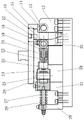
图1为本发明锻造模具的俯视结构示意图。Fig. 1 is a top structural schematic diagram of a forging die of the present invention.
图2为图1中E—E剖面的剖视图。Fig. 2 is a sectional view of section E-E in Fig. 1 .
图3为图1中A—A剖面的剖视图。Fig. 3 is a sectional view of section A-A in Fig. 1 .
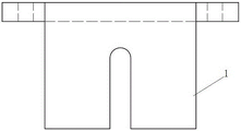
图4为本发明锻造模具的第一斜冲板的侧视结构示意图。Fig. 4 is a side view schematic diagram of the first inclined punching plate of the forging die of the present invention.
图5为本发明锻造模具的夹紧机构中部分零件的分解图。Fig. 5 is an exploded view of some parts in the clamping mechanism of the forging die of the present invention.
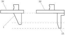
图6为本发明锻造模具的第一斜冲板与第二斜冲板的对比图。Fig. 6 is a comparison diagram of the first inclined punching plate and the second inclined punching plate of the forging die of the present invention.
图7为本发明锻造模具的斜冲模块打开状态图。Fig. 7 is an open state view of the oblique punching module of the forging die of the present invention.
图中:In the picture:
1-第一斜冲板,2-第一磨擦板,3-U型块,4-第一弹簧,5-第一弹簧导杆,6-弹簧压套,7-第二磨擦板,8-墩粗滑块,9-圆形压板,10-墩粗模块,11-夹紧块,12-第一滚轮座,13-第一滚轮轴,14-第一滚轮,15-第二斜冲板,16-第二滚轮,17-第二滚轮轴,18-盖板,19-碟形弹簧滑块,20-第二滚轮座,21-碟形弹簧,22-第一推杆,23-第一销轴,24-第一推杆座,25-第二销轴,26-第三销轴,27-第二弹簧,28-第二弹簧导杆,29-第二弹簧支座,30-第一滑座,31-第二滑座,32-第四销轴,33-第二推杆,34-活动推杆座,35-底板,36-夹紧块座,37-复位滑块,38-第一上模板,39-第二上模板。1-the first inclined punching plate, 2-the first friction plate, 3-U-shaped block, 4-the first spring, 5-the first spring guide rod, 6-spring compression sleeve, 7-the second friction plate, 8- Thick pier slider, 9-circular pressure plate, 10-thick pier module, 11-clamping block, 12-first roller seat, 13-first roller shaft, 14-first roller, 15-second inclined punching plate , 16-second roller, 17-second roller shaft, 18-cover plate, 19-disc spring slider, 20-second roller seat, 21-disc spring, 22-first push rod, 23-the first A pin shaft, 24-the first push rod seat, 25-the second pin shaft, 26-the third pin shaft, 27-the second spring, 28-the second spring guide rod, 29-the second spring support, 30- The first sliding seat, 31-the second sliding seat, 32-the fourth pin, 33-the second push rod, 34-movable push rod seat, 35-bottom plate, 36-clamping block seat, 37-resetting slide block, 38-first template, 39-second template.
具体实施方式detailed description
为了能够更清楚地理解本发明的上述目的、特征和优点,下面结合附图和具体实施方式对本发明进行进一步的详细描述。在下面的描述中阐述了很多具体细节以便于充分理解本发明,但是,本发明还可以采用其他不同于在此描述的其他方式来实施,因此,本发明并不限于下面公开的具体实施例的限制。In order to understand the above-mentioned purpose, features and advantages of the present invention more clearly, the present invention will be further described in detail below in conjunction with the accompanying drawings and specific embodiments. In the following description, many specific details are set forth in order to fully understand the present invention, but the present invention can also be implemented in other ways different from those described here, therefore, the present invention is not limited to the specific embodiments disclosed below limit.
如图1~7所示的一种锻造模具,包括底板35、模座、夹紧机构和斜冲模块,所述模座包括U型块3、夹紧块座36、夹紧块11、墩粗模块10、圆形压板9和墩粗滑块8,所述U型块3固定在底板35上,夹紧块座36、墩粗模块10、圆形压板9和墩粗滑块8依次设置在U型块3的U型槽内,夹紧块座36紧贴U型块3一端内侧边固定,夹紧块11设置在夹紧块座36内,墩粗模块10内设有用于零件锻造的成型槽,墩粗模块10一端端部设有凸缘,通过圆形压板9和螺栓固定在墩粗滑块8一侧,墩粗滑块8另一侧倾斜设置并与U型块3内侧壁间形成“V”型槽,墩粗滑块8能够在夹紧块座36与U型块3侧壁之间滑动;所述U型块3内侧壁与墩粗滑块8的侧壁上分别设有第一磨擦板2和第二磨擦板7,用于减少U型块3和墩粗滑块8的磨损,增长模具使用寿命。A forging die as shown in Figures 1 to 7 includes a
所述夹紧机构包括位于模座两侧的两组第一滑座30、第二滑座31、第一滚轮座12、第二滚轮座20、第一滚轮14、第二滚轮16、碟形弹簧21、碟形弹簧滑块19、第一推杆22、第一推杆座24、第一销轴23、第二销轴25、第三销轴26、第四销轴32、第二推杆33、第二上模板39和第二斜冲板15,所述第一滚轮座12、第二滚轮座20、第一滑座30、第二滑座31从右至左依次固定在底板35上,第一滚轮座12与第二滚轮座20之间形成一底部呈V形的槽;所述第一滚轮14通过第一滚轮轴13固定在第一滚轮座12顶部,第一滚轮14能够绕第一滚轮轴13转动从而减少摩擦;所述第二滚轮座20顶部水平设置有滑槽,第二滚轮16通过第二滚轮轴17嵌设在滑槽内,顶部设有盖板18固定,第二滚轮16能够沿滑槽水平位移,所述碟形弹簧滑块19位于第二滑座31上靠近第二滚轮座20的一侧,第一推杆22一端与碟形弹簧滑块19套接,碟形弹簧21套设在碟形弹簧滑块19上且位于第一推杆22和碟形弹簧滑块19之间,第一推杆22另一端与第一推杆座24套接,第一推杆22和第一推杆座24相接的位置均设有一第一销轴23孔,第一销轴23放置在第一销轴23孔内,第一推杆座24另一端设有第二销轴25孔,第二销轴25放置在第二销轴25孔内,第二滑座31远离第二滚轮座20的一侧上设有活动推杆座34,活动推杆座34上设有活动槽,所述第二销轴25、第三销轴26和第四销轴32均位于活动槽内,且第二销轴25位于第三销轴26和第四销轴32之间;其中,活动槽的长度略小于第二销轴25、第三销轴26和第四销轴32的直径之和,在其他实施例中,第三销轴26和第四销轴32还可以通过上下交错的两根连杆分别与第二销轴25转动连接,以便于辅助限位和力传递;所述第二推杆33垂直于夹紧块11设置,且第二推杆33能够穿过夹紧块座36与夹紧块11接触,用于推紧夹紧块11从而夹紧工件;第二斜冲板15位于第二上模板39下方,且第二斜冲板15与第二上模板39垂直设置,第二斜冲板15底部呈V形,所述第二上模板39用于与冲床或油压机连接,能够驱动第二斜冲板15下压进入第一滚轮座12与第二滚轮座20之间的槽内。The clamping mechanism includes two sets of first sliding
所述斜冲模块包括第一上模板38、第一斜冲板1、第一弹簧导杆5、第一弹簧4和弹簧压套6,第一弹簧导杆5一端穿过U型块3与墩粗滑块8连接,弹簧压套6设置在第一弹簧导杆5另一端端部,第一弹簧4套设在第一弹簧导杆5上且位于U型块3与弹簧压套6之间;第一斜冲板1位于第一上模板38下方,且第一斜冲板1与第一上模板38垂直设置,第一斜冲板1一侧倾斜设置且倾角与滑块的倾角相同,断面呈“V”形,所述第一上模板38用于与冲床或油压机连接,能够驱动第一斜冲板1下压进入墩粗滑块8与U型块3间的“V”型槽内。其中,所述第一斜冲板1中心位置设有能够容纳第一弹簧导杆5穿过的、竖向设置的通槽,第一磨擦板2和第二磨擦板7上也留有能够容纳第一弹簧导杆5穿过的通孔。The inclined punching module includes a first
所述锻造模具还包括复位助推模块,所述复位助推模块包括第二弹簧支座29、第二弹簧导杆28、第二弹簧27和复位滑块37,所述第二弹簧支座29设置在第二滑座31左侧,第二弹簧支座29呈L形,第二弹簧支座29与第二滑座31之间形成空槽,第二弹簧导杆28穿过第二弹簧支座29及第二滑座31上预留的孔且能够在孔内滑动,第二弹簧27套设在第二弹簧导杆28上且位于第二弹簧支座29与第二滑座31之间,复位滑块37位于第二滑座31上且与第二弹簧导杆28端部连接。The forging die also includes a reset booster module, and the reset booster module includes a
其中,所述第二弹簧导杆28、复位滑块37、第一推杆22和碟形弹簧滑块19的轴线均位于同一直线上,所述夹紧块座36、墩粗模块10和第一弹簧导杆5的轴线均位于同一直线上。Wherein, the axes of the second
其中,如图6所示,第一上模板38与第二上模板39位于同一水平线上,第二斜冲板15的长度大于第一斜冲板1的长度,从而使得夹紧行程比墩粗行程提前进行,即墩粗开始瞬间,夹紧机构已经完成工件夹紧。Wherein, as shown in Figure 6, the first
该装置的具体工作过程:先将工件穿过U型块3和夹紧块11,放入墩粗模块10中,然后启动冲床或压力机,驱动第一上模板38和第二上模板39同时下压,从而带动第一斜冲板1和第二斜冲板15同时向下运动;此时,由于第二斜冲板15的长度大于第一斜冲板1的长度,第二斜冲板15先进入第一滚轮座12与第二滚轮座20之间的槽内,推动第二滚轮16在第二滚轮座20内移动至碟形弹簧滑块19这一侧,挤压推动碟形弹簧滑块19移动,从而推动第一推杆22、第一销轴23、第一推杆座24和第二销轴25同时移动(此时碟形弹簧21压缩蓄力),第二销轴25会挤压第三销轴26和第四销轴32,但第三销轴26被活动推杆座34限位无法移动,因此力作用在第四销轴32上使之位移,从而推动第二推杆33向内移动,给夹紧块11提供侧向夹紧力,使得夹紧块11能够夹紧工件防止工件在锻造时向后运动;此时第二弹簧27被压缩,第二弹簧导杆28和复位滑块37向后运动。The specific working process of the device: first pass the workpiece through the U-shaped
工件夹紧时,第一斜冲板1下移至墩粗滑块8与U型块3间的“V”型槽内,推动墩粗滑块8平移,墩粗滑块8推动圆形压板9和墩粗模块10向前运动完成一次锻压,此时第一弹簧导杆5被墩粗滑块8带动前移,第一弹簧4被压缩。When the workpiece is clamped, the first
然后冲床或压力机驱动第一上模板38和第二上模板39同时上移,带动第一斜冲板1和第二斜冲板15同时向上运动,第一弹簧4解除压缩状态提供回复力,推动第一弹簧导杆5向后移动,从而带动墩粗滑块8、圆形压板9和墩粗模块10向后运动,工件脱模;同样的,第二弹簧27和碟形弹簧21解除压缩状态提供回复力,分别推动复位滑块37、第二弹簧导杆28、第二销轴25、第一推杆座24、第一销轴23、第一推杆22、碟形弹簧滑块19、第二滚轮16移动,使提供侧向夹紧力的部件回复到初始位置,解除夹紧块11的夹紧状态。等待下一次工作。Then the punch or press drives the first
以上所述仅为本发明的优选实施例而已,并不用于限制本发明,对于本领域的技术人员来说,本发明可以有各种更改和变化。凡在本发明的精神和原则之内,所作的任何修改、等同替换、改进等,均应包含在本发明的保护范围之内。The above descriptions are only preferred embodiments of the present invention, and are not intended to limit the present invention. For those skilled in the art, the present invention may have various modifications and changes. Any modifications, equivalent replacements, improvements, etc. made within the spirit and principles of the present invention shall be included within the protection scope of the present invention.
Claims (7)
Priority Applications (1)
| Application Number | Priority Date | Filing Date | Title |
|---|---|---|---|
| CN202211292053.6A CN115592064A (en) | 2022-10-21 | 2022-10-21 | a forging mold |
Applications Claiming Priority (1)
| Application Number | Priority Date | Filing Date | Title |
|---|---|---|---|
| CN202211292053.6A CN115592064A (en) | 2022-10-21 | 2022-10-21 | a forging mold |
Publications (1)
| Publication Number | Publication Date |
|---|---|
| CN115592064A true CN115592064A (en) | 2023-01-13 |
Family
ID=84849610
Family Applications (1)
| Application Number | Title | Priority Date | Filing Date |
|---|---|---|---|
| CN202211292053.6A Pending CN115592064A (en) | 2022-10-21 | 2022-10-21 | a forging mold |
Country Status (1)
| Country | Link |
|---|---|
| CN (1) | CN115592064A (en) |
Citations (7)
| Publication number | Priority date | Publication date | Assignee | Title |
|---|---|---|---|---|
| DE2053279A1 (en) * | 1969-12-19 | 1971-06-24 | Lishczinsky P | Remote activating device for clamping ram - of forging press |
| CN204700228U (en) * | 2015-06-09 | 2015-10-14 | 遵化市双剑农机具制造有限公司 | Pier roughcast tool |
| CN106239205A (en) * | 2016-08-22 | 2016-12-21 | 浙江伟联科技股份有限公司 | A kind of reinforcing bar charging reinforcement clamping device |
| CN207057551U (en) * | 2017-07-07 | 2018-03-02 | 重庆霸腾机械有限公司 | A kind of pier nose mould |
| CN112719028A (en) * | 2021-03-29 | 2021-04-30 | 常州纺织服装职业技术学院 | Punching device capable of automatically feeding |
| CN215817997U (en) * | 2021-04-16 | 2022-02-11 | 上海夸父新能源科技有限公司 | A new energy solar panel base |
| CN218340923U (en) * | 2022-10-21 | 2023-01-20 | 江西方大长力汽车零部件有限公司 | Forging die |
-
2022
- 2022-10-21 CN CN202211292053.6A patent/CN115592064A/en active Pending
Patent Citations (7)
| Publication number | Priority date | Publication date | Assignee | Title |
|---|---|---|---|---|
| DE2053279A1 (en) * | 1969-12-19 | 1971-06-24 | Lishczinsky P | Remote activating device for clamping ram - of forging press |
| CN204700228U (en) * | 2015-06-09 | 2015-10-14 | 遵化市双剑农机具制造有限公司 | Pier roughcast tool |
| CN106239205A (en) * | 2016-08-22 | 2016-12-21 | 浙江伟联科技股份有限公司 | A kind of reinforcing bar charging reinforcement clamping device |
| CN207057551U (en) * | 2017-07-07 | 2018-03-02 | 重庆霸腾机械有限公司 | A kind of pier nose mould |
| CN112719028A (en) * | 2021-03-29 | 2021-04-30 | 常州纺织服装职业技术学院 | Punching device capable of automatically feeding |
| CN215817997U (en) * | 2021-04-16 | 2022-02-11 | 上海夸父新能源科技有限公司 | A new energy solar panel base |
| CN218340923U (en) * | 2022-10-21 | 2023-01-20 | 江西方大长力汽车零部件有限公司 | Forging die |
Similar Documents
| Publication | Publication Date | Title |
|---|---|---|
| CN201291267Y (en) | Punch reverse wedge flanging composite die | |
| CN220127267U (en) | Quick bending structure and bending die suitable for symmetrical workpieces | |
| CN117282899B (en) | Forging and pressing device for flange machining | |
| JPH02155524A (en) | Set of tool for combining sheet-shaped metal piece | |
| CN118385383A (en) | Anti-deviation type automobile parts stamping machine | |
| CN218340923U (en) | Forging die | |
| CN109500214B (en) | A mold structure for simultaneously punching four holes in the side wall of barrel-shaped parts and its application | |
| CN209349383U (en) | A combination stamping die | |
| CN221869999U (en) | A stamping die for concentric product parts | |
| CN119187309A (en) | Stamping auxiliary device and heat exchange plate stamping method | |
| CN218109044U (en) | Diaphragm die interlayer punching device | |
| CN218283431U (en) | Sheet metal part mould with positioning function | |
| CN215391695U (en) | Iron shell shaping and forming mechanism | |
| CN212598422U (en) | Positioning mechanism for stamping die | |
| CN210231203U (en) | Bilateral punching die | |
| CN221362077U (en) | Upper die synchronous motion structure of elbow punching machine | |
| CN217141966U (en) | Stamping device is used in case production | |
| CN224115161U (en) | Upper die pushing mechanism for anti-sticking die | |
| CN218925941U (en) | Stamping die for automobile frame | |
| CN214442197U (en) | A punching device suitable for tableware processing | |
| CN221890713U (en) | A punching equipment for pipe production | |
| CN224164485U (en) | A terminal mounting mechanism in wire harness processing | |
| CN221158312U (en) | Arc-shaped workpiece stamping die | |
| CN222491986U (en) | Cold heading die for nut machining | |
| CN220760708U (en) | Hardware stamping die convenient to change |
Legal Events
| Date | Code | Title | Description |
|---|---|---|---|
| PB01 | Publication | ||
| PB01 | Publication | ||
| SE01 | Entry into force of request for substantive examination | ||
| SE01 | Entry into force of request for substantive examination |