CN115592026B - New energy automobile panel stamping die - Google Patents
New energy automobile panel stamping die Download PDFInfo
- Publication number
- CN115592026B CN115592026B CN202211431977.XA CN202211431977A CN115592026B CN 115592026 B CN115592026 B CN 115592026B CN 202211431977 A CN202211431977 A CN 202211431977A CN 115592026 B CN115592026 B CN 115592026B
- Authority
- CN
- China
- Prior art keywords
- stamping
- plate
- fixedly connected
- sliding
- top surface
- Prior art date
- Legal status (The legal status is an assumption and is not a legal conclusion. Google has not performed a legal analysis and makes no representation as to the accuracy of the status listed.)
- Active
Links
Images



Classifications
-
- B—PERFORMING OPERATIONS; TRANSPORTING
- B21—MECHANICAL METAL-WORKING WITHOUT ESSENTIALLY REMOVING MATERIAL; PUNCHING METAL
- B21D—WORKING OR PROCESSING OF SHEET METAL OR METAL TUBES, RODS OR PROFILES WITHOUT ESSENTIALLY REMOVING MATERIAL; PUNCHING METAL
- B21D37/00—Tools as parts of machines covered by this subclass
- B21D37/10—Die sets; Pillar guides
-
- B—PERFORMING OPERATIONS; TRANSPORTING
- B21—MECHANICAL METAL-WORKING WITHOUT ESSENTIALLY REMOVING MATERIAL; PUNCHING METAL
- B21C—MANUFACTURE OF METAL SHEETS, WIRE, RODS, TUBES, PROFILES OR LIKE SEMI-MANUFACTURED PRODUCTS OTHERWISE THAN BY ROLLING; AUXILIARY OPERATIONS USED IN CONNECTION WITH METAL-WORKING WITHOUT ESSENTIALLY REMOVING MATERIAL
- B21C51/00—Measuring, gauging, indicating, counting, or marking devices specially adapted for use in the production or manipulation of material in accordance with subclasses B21B - B21F
-
- B—PERFORMING OPERATIONS; TRANSPORTING
- B21—MECHANICAL METAL-WORKING WITHOUT ESSENTIALLY REMOVING MATERIAL; PUNCHING METAL
- B21D—WORKING OR PROCESSING OF SHEET METAL OR METAL TUBES, RODS OR PROFILES WITHOUT ESSENTIALLY REMOVING MATERIAL; PUNCHING METAL
- B21D22/00—Shaping without cutting, by stamping, spinning, or deep-drawing
- B21D22/02—Stamping using rigid devices or tools
-
- B—PERFORMING OPERATIONS; TRANSPORTING
- B21—MECHANICAL METAL-WORKING WITHOUT ESSENTIALLY REMOVING MATERIAL; PUNCHING METAL
- B21D—WORKING OR PROCESSING OF SHEET METAL OR METAL TUBES, RODS OR PROFILES WITHOUT ESSENTIALLY REMOVING MATERIAL; PUNCHING METAL
- B21D37/00—Tools as parts of machines covered by this subclass
- B21D37/04—Movable or exchangeable mountings for tools
-
- B—PERFORMING OPERATIONS; TRANSPORTING
- B21—MECHANICAL METAL-WORKING WITHOUT ESSENTIALLY REMOVING MATERIAL; PUNCHING METAL
- B21D—WORKING OR PROCESSING OF SHEET METAL OR METAL TUBES, RODS OR PROFILES WITHOUT ESSENTIALLY REMOVING MATERIAL; PUNCHING METAL
- B21D43/00—Feeding, positioning or storing devices combined with, or arranged in, or specially adapted for use in connection with, apparatus for working or processing sheet metal, metal tubes or metal profiles; Associations therewith of cutting devices
- B21D43/003—Positioning devices
-
- B—PERFORMING OPERATIONS; TRANSPORTING
- B21—MECHANICAL METAL-WORKING WITHOUT ESSENTIALLY REMOVING MATERIAL; PUNCHING METAL
- B21D—WORKING OR PROCESSING OF SHEET METAL OR METAL TUBES, RODS OR PROFILES WITHOUT ESSENTIALLY REMOVING MATERIAL; PUNCHING METAL
- B21D45/00—Ejecting or stripping-off devices arranged in machines or tools dealt with in this subclass
- B21D45/02—Ejecting devices
Landscapes
- Engineering & Computer Science (AREA)
- Mechanical Engineering (AREA)
- Shaping Metal By Deep-Drawing, Or The Like (AREA)
Abstract
The invention discloses a new energy automobile panel stamping die, which comprises a base, wherein a stamping groove is formed in the base; the base is fixedly connected with a supporting component, the supporting component is connected with a punching component in a sliding manner, and the punching component is correspondingly arranged with the punching groove; side clamp assemblies are symmetrically arranged on the side walls of the support assemblies, which face the stamping grooves, and the side clamp assemblies are detachably connected with blanks in the stamping grooves; the two sides of the stamping component are provided with a jacking component which is detachably connected with the top surface of the blank; the punching assembly comprises a sliding plate which is in sliding connection with the supporting assembly, a plurality of connecting rods are in sliding connection with the sliding plate, punching heads are fixedly connected to the bottoms of the connecting rods, and a transmission assembly is arranged between the punching heads and the sliding plate. The invention has the advantages of high stamping speed, high stamping efficiency, gradually increased stamping pressure in the stamping process and strong controllability, reduces the damage of constant impact pressure to blanks, improves the stamping quality, reduces the generation of defective products and improves the production benefit.
Description
Technical Field
The invention relates to the technical field of automobile production equipment, in particular to a new energy automobile panel stamping die.
Background
With the increasingly strict environmental protection requirements, the requirements of new energy automobiles are gradually increased; the new energy automobile panel needs to be stamped and formed in the production process, equipment used for stamping is called a stamping die, the stamping die is important in stamping and forming, and batch stamping production is difficult to carry out without a stamping die meeting the requirements; without an advanced stamping die, an advanced stamping process cannot be realized, and the stamping process, the stamping die and the stamping material form three elements of stamping processing, and only the three elements are combined with each other to obtain the stamping part. However, when the existing stamping die is used for stamping, the panel of the new energy automobile is not firmly fixed, so that the stamping part is easy to deviate, and the stamping quality is affected; meanwhile, the impact pressure and impact speed of stamping in the stamping process of the stamping die are not easy to control, and the stamping part is easy to damage. Therefore, a new energy automobile panel stamping die needs to be designed to solve the above problems.
Disclosure of Invention
The invention aims to provide a new energy automobile panel stamping die to solve the problems in the prior art.
In order to achieve the above object, the present invention provides the following solutions: the invention provides a new energy automobile panel stamping die, which comprises a base, wherein a stamping groove is formed in the base; the base is fixedly connected with a supporting component, the supporting component is connected with a punching component in a sliding manner, and the punching component is arranged corresponding to the punching groove;
side clamp assemblies are symmetrically arranged on the side walls of the support assemblies, which face the stamping grooves, and the side clamp assemblies are detachably connected with blanks in the stamping grooves;
the two sides of the stamping component are provided with a jacking component which is detachably connected with the top surface of the blank;
the stamping assembly comprises a sliding plate which is in sliding connection with the supporting assembly, the sliding plate is in sliding connection with a plurality of connecting rods, stamping heads are fixedly connected to the bottom ends of the connecting rods, and a transmission assembly is arranged between the stamping heads and the sliding plate;
an ejection assembly is arranged in the base, and the ejection assembly is arranged corresponding to the bottom end of the punching groove.
Preferably, the top end of the stamping head is fixedly connected with a connecting plate, and the connecting rod is fixedly connected with the top end of the connecting plate; the top end of the sliding plate is fixedly connected with the output end of the stamping hydraulic cylinder fixedly arranged on the supporting component, and the transmission component is electrically connected with the stamping hydraulic cylinder.
Preferably, the transmission assembly comprises an outer sliding cylinder and an inner sliding cylinder which are connected in a sliding way, the top end of the outer sliding cylinder is fixedly connected with the sliding plate, and the bottom end of the inner sliding cylinder is fixedly connected with the top surface of the connecting plate; the pressure sensor is fixedly arranged on the top surface of the inner cavity of the outer sliding cylinder and electrically connected with the stamping hydraulic cylinder, a force transmission spring is fixedly connected between the bottom surface of the inner cavity of the inner sliding cylinder and the top surface of the inner cavity of the outer sliding cylinder, and the force transmission spring is abutted to the pressure sensor through a transmission plate.
Preferably, the top end of the connecting rod is in threaded connection with a positioning nut, and the bottom surface of the positioning nut is detachably connected with the top surface of the sliding plate.
Preferably, the support assembly comprises upright posts symmetrically fixedly connected to the top surface of the base, and two ends of the sliding plate are respectively in sliding contact with the two upright posts; the top ends of the two upright posts are fixedly connected with mounting frames, and the stamping hydraulic cylinder is fixedly arranged on the mounting frames; the side clamp assembly is connected to the upright in a sliding manner.
Preferably, the side clamping assembly comprises a sliding block which is connected to the upright post in a sliding way, one end of the sliding block, which faces the stamping groove, is fixedly connected with a side clamping push rod, and the output end of the side clamping push rod is fixedly connected with a side clamping plate which is abutted against the side wall of the blank; and the slider is connected with a jacking bolt in a threaded manner, and the jacking bolt is abutted with the upright post.
Preferably, the jacking component comprises a fixed cylinder fixedly arranged on the bottom surface of the sliding plate, a movable rod is connected in an inner cavity of the fixed cylinder in a sliding manner, a jacking plate is fixedly connected to the bottom surface of the movable rod, and the jacking plate is abutted to the top surface of the blank; the inner cavity of the fixed cylinder is fixedly connected with a jacking spring, and the jacking spring is fixedly connected with the top surface of the movable rod; the bottom surface of the pressing plate is lower than the bottom surface of the stamping head.
Preferably, the base comprises a bottom plate, the top surface of the bottom plate is fixedly connected with a workbench through a plurality of buffer components, and the stamping groove is formed in the top surface of the workbench; the upright post is fixedly connected to the top surface of the workbench; the ejection assembly is fixedly arranged on the top surface of the bottom plate, and penetrates through the workbench to be arranged corresponding to the bottom surface of the punching groove.
Preferably, the ejection assembly comprises an ejection hydraulic cylinder fixedly installed on the top surface of the bottom plate, the output end of the ejection hydraulic cylinder penetrates through the workbench and then stretches into the stamping groove, an ejection plate is fixedly connected to the top surface of the output end of the ejection hydraulic cylinder, and the ejection plate is in butt joint with the blank.
Preferably, the buffer assembly comprises buffer cylinders which are correspondingly arranged up and down, and the two buffer cylinders are fixedly connected with the top surface of the bottom plate and the bottom surface of the workbench respectively; a buffer plate is hermetically and slidingly connected in the two buffer cylinders, and buffer liquid is filled between the buffer plate and the buffer cylinders; a supporting rod is fixedly connected between the two buffer plates.
The invention discloses the following technical effects: the invention discloses a new energy automobile panel stamping die, which is characterized in that a blank is stamped into a required shape through a stamping assembly and a stamping groove formed in a base, so that the stamping speed is high, and the stamping efficiency is high; the blank is fixed by the side clamp assembly and the top pressure assembly in the stamping process, so that the quality of the panel is prevented from being reduced due to the deviation of the blank in the stamping process, the stamping quality is improved, and the stamping yield is improved; an ejection assembly is arranged in the base and used for ejecting the punched panel out of the punching groove after the punching is finished, so that the panel is prevented from being clamped in the punching groove, and the punching efficiency is improved; the stamping head is connected to the bottom end of the sliding plate through the combined action of the transmission component and the connecting rod, in a non-stamping state, the stamping head is suspended at the bottom end of the sliding plate through the connecting rod, fatigue of the transmission component is prevented, the service life is prolonged, when the stamping head is stamped, after the stamping head contacts a blank, the connecting rod slides between the connecting rod and the sliding plate, the suspension effect is lost, the stamping head is only used for positioning, the pressure of the sliding plate is gradually increased and transmitted to the stamping head, the impact force of the stamping head is gradually increased, the blank is not damaged, and meanwhile, the stamping pressure controllability is strong. The invention has the advantages of high stamping speed, high stamping efficiency, gradually increased stamping pressure in the stamping process and strong controllability, reduces the damage of constant impact pressure to blanks, improves the stamping quality, reduces the generation of defective products and improves the production benefit.
Drawings
In order to more clearly illustrate the embodiments of the present invention or the technical solutions in the prior art, the drawings that are needed in the embodiments will be briefly described below, and it is obvious that the drawings in the following description are only some embodiments of the present invention, and other drawings may be obtained according to these drawings without inventive effort for a person skilled in the art.
FIG. 1 is a schematic diagram of a stamping die structure for a panel of a new energy automobile;
FIG. 2 is a schematic top view of the post of the present invention;
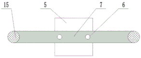
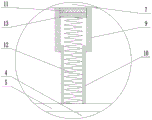
FIG. 3 is an enlarged partial cross-sectional view of FIG. 1A;
FIG. 4 is an enlarged view of a portion of B in FIG. 1;
FIG. 5 is an enlarged partial cross-sectional view of C of FIG. 1;
1, a base; 2. stamping a groove; 3. a blank; 4. punching heads; 5. a connecting plate; 6. a connecting rod; 7. a sliding plate; 8. a stamping hydraulic cylinder; 9. an outer slide cylinder; 10. an inner slide tube; 11. a pressure sensor; 12. a force transmission spring; 13. a drive plate; 14. positioning a nut; 15. a column; 16. a mounting frame; 17. a slide block; 18. a side clamping push rod; 19. a side clamping plate; 20. a jack bolt; 21. a fixed cylinder; 22. a movable rod; 23. a top pressing plate; 24. a pressing spring; 25. a bottom plate; 26. a buffer assembly; 27. a work table; 28. ejecting a hydraulic cylinder; 29. an ejector plate; 30. a buffer tube; 31. a buffer plate; 32. a buffer; 33. a support rod; 34. a cushion pad; 35. a limit groove; 36. and a limiting block.
Detailed Description
The following description of the embodiments of the present invention will be made clearly and completely with reference to the accompanying drawings, in which it is apparent that the embodiments described are only some embodiments of the present invention, but not all embodiments. All other embodiments, which can be made by those skilled in the art based on the embodiments of the invention without making any inventive effort, are intended to be within the scope of the invention.
In order that the above-recited objects, features and advantages of the present invention will become more readily apparent, a more particular description of the invention will be rendered by reference to the appended drawings and appended detailed description.
Referring to fig. 1-5, the invention provides a new energy automobile panel stamping die, which comprises a base 1, wherein a stamping groove 2 is formed in the base 1; the base 1 is fixedly connected with a supporting component, the supporting component is connected with a punching component in a sliding way, and the punching component is correspondingly arranged with the punching groove 2;
side clamp assemblies are symmetrically arranged on the side walls of the support assemblies, facing the stamping groove 2, and are detachably connected with the blank 3 in the stamping groove 2;
the two sides of the stamping component are provided with a jacking component which is detachably connected with the top surface of the blank 3;
the stamping assembly comprises a sliding plate 7 which is in sliding connection with the supporting assembly, the sliding plate 7 is in sliding connection with a plurality of connecting rods 6, the bottom ends of the connecting rods 6 are fixedly connected with stamping heads 4, and a transmission assembly is arranged between the stamping heads 4 and the sliding plate 7;
an ejection assembly is arranged in the base 1 and corresponds to the bottom end of the stamping groove 2.
The invention discloses a new energy automobile panel stamping die, which is characterized in that a blank is stamped into a required shape through a stamping assembly and a stamping groove 2 formed in a base 1, so that the stamping speed is high, and the stamping efficiency is high; the blank 3 is fixed by the side clamping assembly and the jacking assembly in the stamping process, so that the quality of a panel is prevented from being reduced due to the deviation of the blank 3 in the stamping process, the stamping quality is improved, and the stamping yield is improved; an ejection assembly is arranged in the base 1 and used for ejecting the punched panel out of the punching groove 2 after punching is finished, so that the panel is prevented from being clamped in the punching groove 2, and the punching efficiency is improved; the punching press head 4 is connected in the sliding plate 7 bottom through drive assembly and connecting rod 6 pole combined action, non-punching press state, and punching press head 4 is hung in the bottom of sliding plate 7 by connecting rod 6, prevents drive assembly and produces tired, increase of service life, and during punching press, after punching press head 4 contacted blank 3, slide between connecting rod 6 and the sliding plate 7, loses the effect of hanging, only is used for the location, and the pressure of sliding plate 7 progressively increases and transmits for punching press head 4, makes the impact force of punching press head 4 progressively increase, can not harm blank 3, and punching press pressure controllability is strong simultaneously.
In a further optimized scheme, the top end of the stamping head 4 is fixedly connected with a connecting plate 5, and a connecting rod 6 is fixedly connected at the top end of the connecting plate 5; the top end of the sliding plate 7 is fixedly connected with the output end of a stamping hydraulic cylinder 8 fixedly arranged on the supporting component, and the transmission component is electrically connected with the stamping hydraulic cylinder 8. The area of the connecting plate 5 is larger than that of the stamping head 4, so that the connecting rod 6 is convenient to connect, and meanwhile, stress is dispersed, so that the stress is more uniform; the transmission component is electrically connected with the stamping hydraulic cylinder 8, so that the stamping pressure is conveniently controlled, incomplete stamping caused by too small pressure is prevented, and blank 3 breakage caused by too large stamping pressure is also prevented.
Further, the bottom rigid coupling of connecting plate 5 has blotter 34, and blotter 34 sets up around stamping head 4 lateral wall, and during the punching press, blotter 34 and base 1 top surface contact prevent that connecting plate 5 and base 1 from producing hard collision, reduced noise intensity, also prolonged the life of equipment.
In a further optimized scheme, the transmission assembly comprises an outer sliding cylinder 9 and an inner sliding cylinder 10 which are in sliding connection, the top end of the outer sliding cylinder 9 is fixedly connected with the sliding plate 7, and the bottom end of the inner sliding cylinder 10 is fixedly connected with the top surface of the connecting plate 5; the top surface of the inner cavity of the outer sliding cylinder 9 is fixedly provided with a pressure sensor 11 which is electrically connected with the stamping hydraulic cylinder 8, a force transmission spring 12 is fixedly connected between the bottom surface of the inner cavity of the inner sliding cylinder 10 and the top surface of the inner cavity of the outer sliding cylinder 9, and the force transmission spring 12 is abutted with the pressure sensor 11 through a transmission plate 13. At the non-stamping moment, the weight of the stamping head 4 is pulled by the connecting rod 6, the force transmission assembly is not stressed, the force transmission spring 12 is in a free state, fatigue deformation caused by long-time compression is prevented, and the service life is prolonged; during punching, the punching head 4 is contacted with the blank 3, a reverse supporting force is generated on the punching head 4, the connecting rod 6 slides with the sliding plate 7, no pressure is generated on the punching head 4, the pressure of the punching hydraulic cylinder 8 enables the sliding plate 7 to approach to the punching head 4, the force transmission spring 12 is compressed, the punching head 4 is subjected to pressure, and along with the compression of the force transmission spring 12, the pressure of the punching head 4 is larger until the blank 3 is punched into the punching groove 2 to form a required shape, the pressure sensor 11 is used for measuring the pressure of the force transmission spring 12 on the punching head 4, after the pressure reaches the set punching pressure, the punching hydraulic cylinder 8 is controlled to stop loading, after 3s-5s, the punching hydraulic cylinder 8 is reversely output, the sliding plate 7 is pulled to rise, the pressure of the punching head 4 is gradually reduced until the force transmission spring 12 is restored to a free state again, and the sliding plate 7 pulls the punching head 4 up through the connecting rod 6, so that one punching process is completed.
Further optimizing scheme, the top threaded connection of connecting rod 6 has positioning nut 14, and the bottom surface of positioning nut 14 is connected with the top surface of sliding plate 7 can be dismantled. The positioning nut 14 is mainly used for positioning the sliding stroke of the connecting rod 6, when the connecting rod 6 hangs the punching head 4, the positioning nut 14 is abutted with the top surface of the sliding plate 7, and when punching is performed, the positioning nut 14 moves upwards and is separated from the sliding plate 7 under the driving of the connecting rod 6.
In a further optimized scheme, the supporting component comprises upright posts 15 symmetrically fixedly connected to the top surface of the base 1, and two ends of the sliding plate 7 are respectively in sliding contact with the two upright posts 15; the top ends of the two upright posts 15 are fixedly connected with a mounting frame 16, and the stamping hydraulic cylinder 8 is fixedly arranged on the mounting frame 16; the side clamp assembly is slidably attached to the column 15. The upright post 15 limits the movement of the sliding plate 7 to prevent deflection, and meanwhile, a movement stroke is provided for the stamping head 4 through the mounting frame 16 and the sliding plate 7, so that the assembly line production is convenient when stamping is finished; the upright 15 also provides a securement point for the side clamp assembly.
In a further optimized scheme, the side clamp assembly comprises a sliding block 17 which is connected to the upright post 15 in a sliding way, one end of the sliding block 17 facing the stamping groove 2 is fixedly connected with a side clamp push rod 18, and the output end of the side clamp push rod 18 is fixedly connected with a side clamp plate 19 which is abutted against the side wall of the blank 3; the slider 17 is screwed with a jack bolt 20, and the jack bolt 20 abuts against the column 15. When in use, the jack bolt 20 is firstly loosened, the sliding block 17 is adjusted to a proper position, and then the jack bolt 20 is tightened again; placing the blank 3 on the base 1 at a position corresponding to the punching groove 2, starting the side clamping push rod 18, and clamping the blank 3 through the side clamping plate 19; at the same time, the blank 3 can be centered once due to the symmetry of the two side clamping plates 19.
In a further optimized scheme, the jacking assembly comprises a fixed cylinder 21 fixedly arranged on the bottom surface of the sliding plate 7, a movable rod 22 is slidably connected in an inner cavity of the fixed cylinder 21, a jacking plate 23 is fixedly connected to the bottom surface of the movable rod 22, and the jacking plate 23 is abutted to the top surface of the blank 3; the inner cavity of the fixed cylinder 21 is fixedly connected with a jacking spring 24, and the jacking spring 24 is fixedly connected with the top surface of the movable rod 22; the bottom surface of the pressing plate 23 is lower than the bottom surface of the punch 4. When the sliding plate 7 is pressed down, the pressing plate 23 contacts the blank 3 before the stamping head 4, along with the pressing down of the sliding plate 7, the movable rod 22 gradually slides upwards along the inner cavity of the fixed cylinder 21, the pressing spring 24 is compressed, along with the shrinkage of the pressing spring 24, the pressure on the movable rod 22 is also increased, the blank 3 is further gradually pressed, and the stability of the blank 3 is improved.
Further, the side wall of the fixed cylinder 21 is longitudinally provided with a plurality of limit grooves 35, the top end of the movable rod 22 is fixedly connected with a limit block 36, the limit block 36 is correspondingly arranged and slidingly connected with the limit groove 35, and the top end of the push spring 24 is fixedly connected with the top end of the limit block 36; the stopper 36 and the stopper groove 35 provide a stopper for the movement of the movable lever 22.
In a further optimized scheme, the base 1 comprises a bottom plate 25, the top surface of the bottom plate 25 is fixedly connected with a workbench 27 through a plurality of buffer assemblies 26, and the stamping groove 2 is formed in the top surface of the workbench 27; the upright post 15 is fixedly connected to the top surface of the workbench 27; the ejection assembly is fixedly arranged on the top surface of the bottom plate 25, and passes through the workbench 27 and is correspondingly arranged on the bottom surface of the punching groove 2. The bottom plate 25 is fixed on the floor of the workshop, so that the device is stably installed, and the workbench 27 is used as a proceeding position of the stamping process and is connected with other production lines (not shown in the figure); a buffer component 26 is arranged between the bottom plate 25 and the workbench 27 and is used for buffering vibration in the stamping process, so that the impact vibration to the bottom plate 25 is reduced, the bottom plate 25 is prevented from being fixed and loosened with a workshop, the stability of equipment is improved, and the service life of the equipment is prolonged; the ejection assembly is fixedly mounted on the bottom plate 25, and receives small impact shock.
In a further optimized scheme, the ejection assembly comprises an ejection hydraulic cylinder 28 fixedly arranged on the top surface of the bottom plate 25, the output end of the ejection hydraulic cylinder 28 penetrates through the workbench 27 and then stretches into the stamping groove 2, the top surface of the output end of the ejection hydraulic cylinder 28 is fixedly connected with an ejection plate 29, and the ejection plate 29 is abutted with the blank 3. After the stamping is finished, the blank 3 is attached to the stamping groove 2, the ejection hydraulic cylinder 28 is started, and the ejection plate 29 ejects the blank 3 in the stamping groove 2, so that the blank is convenient to transfer to the next working procedure.
Further, the bottom of the punching groove 2 is provided with a groove matched with the ejector plate 29, the ejector plate 29 is embedded into the groove when retracted, and the top surface of the ejector plate 29 is flush with the bottom surface of the punching groove 2, so that punching errors are prevented.
In a further optimized scheme, the buffer assembly 26 comprises buffer cylinders 30 which are correspondingly arranged up and down, and the two buffer cylinders 30 are fixedly connected with the top surface of the bottom plate 25 and the bottom surface of the workbench 27 respectively; a buffer plate 31 is sealed and slidingly connected in the two buffer cylinders 30, and buffer liquid 32 is filled between the buffer plate 31 and the buffer cylinders 30; a supporting rod 33 is fixedly connected between the two buffer plates 31. Buffer solution 32 is filled between buffer plate 31 and buffer tube 30, make buffer plate 31 not with bottom plate 25 and workstation 27 direct contact, buffer solution 32 absorption part in the vibrations top that stamping process workstation 27 produced, convert into buffer solution 32's internal energy, then pass through buffer plate 31 and bracing piece 33 after again and transmit buffer solution 32 of below, after the twice absorption of buffer solution 32, the vibrations that transmit to bottom plate 25 are greatly reduced, bottom plate 25 and workshop bottom surface's not hard up has been reduced, equipment's stability has been improved, stamping quality has been improved, the security has been improved simultaneously.
Further, the buffer 32 is preferably an incompressible liquid of relatively high viscosity, such as L-HM46 hydraulic oil; since the buffer 32 is incompressible and viscous, it can act as a damping and absorb shock.
The using method comprises the following steps:
placing the blank 3 on a workbench 27, aligning the blank 3 with the punching groove 2, and then starting a side clamping push rod 18 to clamp the side edges; starting a stamping hydraulic cylinder 8 to drive a sliding plate 7 to descend, and hanging a belt of the sliding plate 7 through a connecting rod 6 to move a stamping head 4 downwards until the stamping head 4 contacts with the top surface of a blank 3; before the punch 4 contacts the blank 3, the pressing assembly contacts the blank 3, and gradually presses the blank 3 as the slide plate 7 is pressed down.
The sliding plate 7 continues to descend, the connecting rod 6 does not apply force to the stamping head 4 any more, the pressure of the sliding plate 7 is transmitted to the stamping head 4 through the force transmission component, the pressure of the stamping head 4 to the blank 3 is gradually increased, the blank 3 is pressed into the stamping groove 2 until the pressure of the force transmission spring 12 to the pressure sensor 11 reaches a preset value, the blank 3 is completely attached to the stamping groove 2 at the moment, and the buffer cushion 34 falls onto the top surface of the workbench 27.
After 3s-5s, the sliding plate 7 is driven to rise through the stamping hydraulic cylinder 8, the pressure on the stamping head 4 is gradually reduced, and finally no alignment is carried out, so that pressure is generated, at the moment, the positioning nut 14 is in contact with the sliding plate 7, the sliding plate 7 drives the stamping head 4 to rise through the connecting rod 6, the blank 3 is separated, and meanwhile, the jacking assembly is also loosened along with the rising of the sliding plate 7.
The side clamping assembly is loosened, the ejection hydraulic cylinder 28 is started, the blank 3 is ejected out of the stamping groove 2, and the blank is transferred to the next working procedure, so that the whole stamping process is completed.
The invention has the advantages of high stamping speed, high stamping efficiency, gradually increased stamping pressure in the stamping process and strong controllability, reduces the damage of constant impact pressure to the blank 3, improves the stamping quality, reduces the generation of defective products and improves the production benefit.
In the description of the present invention, it should be understood that the terms "longitudinal," "transverse," "upper," "lower," "front," "rear," "left," "right," "vertical," "horizontal," "top," "bottom," "inner," "outer," and the like indicate or are based on the orientation or positional relationship shown in the drawings, merely to facilitate description of the present invention, and do not indicate or imply that the devices or elements referred to must have a particular orientation, be constructed and operated in a particular orientation, and thus should not be construed as limiting the present invention.
The foregoing embodiments are merely illustrative of the preferred embodiments of the present invention, and the scope of the present invention is not limited thereto, but various modifications and improvements made by those skilled in the art to which the present invention pertains are made without departing from the spirit of the present invention, and all changes and modifications and improvements fall within the scope of the present invention as defined in the appended claims.
Claims (7)
1. The utility model provides a new energy automobile panel stamping die which characterized in that: the device comprises a base (1), wherein a stamping groove (2) is formed in the base (1); the base (1) is fixedly connected with a supporting component, the supporting component is connected with a punching component in a sliding manner, and the punching component is arranged corresponding to the punching groove (2);
side clamp assemblies are symmetrically arranged on the side walls of the support assemblies, which face the stamping grooves (2), and the side clamp assemblies are detachably connected with the blanks (3) in the stamping grooves (2);
the two sides of the stamping component are provided with a jacking component which is detachably connected with the top surface of the blank (3);
the stamping assembly comprises a sliding plate (7) which is in sliding connection with the supporting assembly, the sliding plate (7) is in sliding connection with a plurality of connecting rods (6), stamping heads (4) are fixedly connected to the bottom ends of the connecting rods (6), and a transmission assembly is arranged between the stamping heads (4) and the sliding plate (7);
an ejection assembly is arranged in the base (1), and the ejection assembly is arranged corresponding to the bottom end of the stamping groove (2);
the transmission assembly comprises an outer sliding cylinder (9) and an inner sliding cylinder (10) which are connected in a sliding way, the top end of the outer sliding cylinder (9) is fixedly connected with the sliding plate (7), and the bottom end of the inner sliding cylinder (10) is fixedly connected with the top surface of the connecting plate (5);
the support component comprises upright posts (15) symmetrically fixedly connected to the top surface of the base (1), and two ends of the sliding plate (7) are respectively in sliding contact with the two upright posts (15);
the jacking assembly comprises a fixed cylinder (21) fixedly arranged on the bottom surface of the sliding plate (7), a movable rod (22) is connected to the inner cavity of the fixed cylinder (21) in a sliding mode, a jacking plate (23) is fixedly connected to the bottom surface of the movable rod (22), and the jacking plate (23) is abutted to the top surface of the blank (3); the inner cavity of the fixed cylinder (21) is fixedly connected with a jacking spring (24), and the jacking spring (24) is fixedly connected with the top surface of the movable rod (22); the bottom surface of the pressing plate (23) is lower than the bottom surface of the stamping head (4);
the base (1) comprises a bottom plate (25), wherein the top surface of the bottom plate (25) is fixedly connected with a workbench (27) through a plurality of buffer components (26), and the stamping groove (2) is formed in the top surface of the workbench (27); the upright post (15) is fixedly connected to the top surface of the workbench (27); the ejection assembly is fixedly arranged on the top surface of the bottom plate (25), and penetrates through the workbench (27) to be arranged corresponding to the bottom surface of the stamping groove (2);
the ejection assembly comprises an ejection hydraulic cylinder (28) fixedly arranged on the top surface of the bottom plate (25), the output end of the ejection hydraulic cylinder (28) penetrates through the workbench (27) and then stretches into the stamping groove (2), an ejection plate (29) is fixedly connected to the top surface of the output end of the ejection hydraulic cylinder (28), and the ejection plate (29) is abutted to the blank (3).
2. The new energy automobile panel stamping die of claim 1, wherein: the top end of the stamping head (4) is fixedly connected with a connecting plate (5), and the connecting rod (6) is fixedly connected with the top end of the connecting plate (5); the top end of the sliding plate (7) is fixedly connected with the output end of a stamping hydraulic cylinder (8) fixedly mounted on the supporting component, and the transmission component is electrically connected with the stamping hydraulic cylinder (8).
3. The new energy automobile panel stamping die of claim 2, wherein: the pressure sensor (11) electrically connected with the stamping hydraulic cylinder (8) is fixedly arranged on the top surface of the inner cavity of the outer sliding cylinder (9), a force transmission spring (12) is fixedly connected between the bottom surface of the inner cavity of the inner sliding cylinder (10) and the top surface of the inner cavity of the outer sliding cylinder (9), and the force transmission spring (12) is abutted with the pressure sensor (11) through a transmission plate (13).
4. The new energy automobile panel stamping die of claim 2, wherein: the top end of the connecting rod (6) is in threaded connection with a positioning nut (14), and the bottom surface of the positioning nut (14) is detachably connected with the top surface of the sliding plate (7).
5. The new energy automobile panel stamping die of claim 1, wherein: the top ends of the two upright posts (15) are fixedly connected with mounting frames (16), and the stamping hydraulic cylinder (8) is fixedly arranged on the mounting frames (16); the side clamp assembly is slidingly connected to the upright (15).
6. The new energy automobile panel stamping die of claim 5, wherein: the side clamp assembly comprises a sliding block (17) which is connected to the upright post (15) in a sliding way, one end of the sliding block (17) facing the stamping groove (2) is fixedly connected with a side clamp push rod (18), and the output end of the side clamp push rod (18) is fixedly connected with a side clamp plate (19) which is abutted to the side wall of the blank (3); the slider (17) is connected with a jacking bolt (20) in a threaded mode, and the jacking bolt (20) is abutted to the upright post (15).
7. The new energy automobile panel stamping die of claim 1, wherein: the buffer assembly (26) comprises buffer cylinders (30) which are correspondingly arranged up and down, and the two buffer cylinders (30) are fixedly connected with the top surface of the bottom plate (25) and the bottom surface of the workbench (27) respectively; a buffer plate (31) is hermetically and slidingly connected in the two buffer cylinders (30), and buffer liquid (32) is filled between the buffer plate (31) and the buffer cylinders (30); a supporting rod (33) is fixedly connected between the two buffer plates (31).
Priority Applications (1)
| Application Number | Priority Date | Filing Date | Title |
|---|---|---|---|
| CN202211431977.XA CN115592026B (en) | 2022-11-16 | 2022-11-16 | New energy automobile panel stamping die |
Applications Claiming Priority (1)
| Application Number | Priority Date | Filing Date | Title |
|---|---|---|---|
| CN202211431977.XA CN115592026B (en) | 2022-11-16 | 2022-11-16 | New energy automobile panel stamping die |
Publications (2)
| Publication Number | Publication Date |
|---|---|
| CN115592026A CN115592026A (en) | 2023-01-13 |
| CN115592026B true CN115592026B (en) | 2023-04-25 |
Family
ID=84852914
Family Applications (1)
| Application Number | Title | Priority Date | Filing Date |
|---|---|---|---|
| CN202211431977.XA Active CN115592026B (en) | 2022-11-16 | 2022-11-16 | New energy automobile panel stamping die |
Country Status (1)
| Country | Link |
|---|---|
| CN (1) | CN115592026B (en) |
Families Citing this family (2)
| Publication number | Priority date | Publication date | Assignee | Title |
|---|---|---|---|---|
| CN116351959B (en) * | 2023-03-31 | 2023-09-15 | 常州洛合精密机械有限公司 | Adjusting structure for continuous stamping die of drawing frame sliding plate |
| CN117245028A (en) * | 2023-08-23 | 2023-12-19 | 宁波欣润密封科技有限公司 | An automatic stamping mechanism for automobile gaskets |
Citations (1)
| Publication number | Priority date | Publication date | Assignee | Title |
|---|---|---|---|---|
| CN216397746U (en) * | 2021-11-28 | 2022-04-29 | 上海戴德斯勒模具技术有限公司 | Stamping die for automobile fastener |
Family Cites Families (4)
| Publication number | Priority date | Publication date | Assignee | Title |
|---|---|---|---|---|
| JP3688750B2 (en) * | 1995-04-06 | 2005-08-31 | 株式会社アマダワシノ | Die mounting mechanism of shape steel processing machine |
| CN106862356B (en) * | 2017-03-02 | 2018-11-02 | 苏州廖若机电科技有限公司 | A kind of automatic stocking formula stainless steel circular sheet molding machine |
| CN110681780A (en) * | 2019-10-23 | 2020-01-14 | 湘潭珺旭科技有限公司 | Automobile seat stamping die |
| CN111687316B (en) * | 2020-06-24 | 2022-02-08 | 东莞市京品精密模具有限公司 | Moulding forming die for metal shaping |
-
2022
- 2022-11-16 CN CN202211431977.XA patent/CN115592026B/en active Active
Patent Citations (1)
| Publication number | Priority date | Publication date | Assignee | Title |
|---|---|---|---|---|
| CN216397746U (en) * | 2021-11-28 | 2022-04-29 | 上海戴德斯勒模具技术有限公司 | Stamping die for automobile fastener |
Also Published As
| Publication number | Publication date |
|---|---|
| CN115592026A (en) | 2023-01-13 |
Similar Documents
| Publication | Publication Date | Title |
|---|---|---|
| CN115592026A (en) | New energy automobile panel stamping die | |
| CN212652524U (en) | Stamping die convenient to dismouting stamping die head | |
| CN108787808B (en) | Quick bending equipment for safe case | |
| CN109807601B (en) | Brake cylinder press-fitting tool and method | |
| CN218693264U (en) | Riveting clamp and double-station numerical control riveting press | |
| CN217475289U (en) | Secondary pressurizing press machine for pulley bearing of lifting machine | |
| CN218775530U (en) | Automobile connector produces stamping die | |
| CN217990548U (en) | Multi-station stamping mechanism for automobile parts | |
| CN215355483U (en) | Bending machine for spare and accessory part production | |
| CN217315692U (en) | Guide sleeve forging and pressing device for high-pressure oil cylinder of construction machinery | |
| CN215697038U (en) | Sheet metal part bending equipment | |
| CN111889604A (en) | High-precision forging and pressing equipment | |
| CN214601277U (en) | Novel hydraulic press | |
| CN212293315U (en) | Workpiece frame-removing device | |
| CN221272118U (en) | Screw press with shock-absorbing structure | |
| CN201280040Y (en) | Apparatus for assembling band spring on axle | |
| CN223399044U (en) | Pressure maintaining device | |
| CN201566032U (en) | Fully-automatic bidirectional pressure adding brick making machine | |
| CN223406514U (en) | Fixing tool for workpiece end face milling equipment | |
| CN219683790U (en) | Taper hole stamping equipment | |
| CN218430166U (en) | Press machine assembly with buffering and damping effects | |
| CN220497462U (en) | Stamping die of hardware product | |
| CN221135747U (en) | Press mounting mechanism for piston rod of hydraulic cylinder | |
| CN223058408U (en) | A hydraulic top glue stamping parts riveting fixture | |
| CN217617163U (en) | Punching device for automobile control arm |
Legal Events
| Date | Code | Title | Description |
|---|---|---|---|
| PB01 | Publication | ||
| PB01 | Publication | ||
| SE01 | Entry into force of request for substantive examination | ||
| SE01 | Entry into force of request for substantive examination | ||
| GR01 | Patent grant | ||
| GR01 | Patent grant |