CN115584702A - Irrigation canals and ditches for hydraulic engineering construction level equipment - Google Patents
Irrigation canals and ditches for hydraulic engineering construction level equipment Download PDFInfo
- Publication number
- CN115584702A CN115584702A CN202210835006.5A CN202210835006A CN115584702A CN 115584702 A CN115584702 A CN 115584702A CN 202210835006 A CN202210835006 A CN 202210835006A CN 115584702 A CN115584702 A CN 115584702A
- Authority
- CN
- China
- Prior art keywords
- frame
- mounting frame
- mounting
- sliding frame
- electric push
- Prior art date
- Legal status (The legal status is an assumption and is not a legal conclusion. Google has not performed a legal analysis and makes no representation as to the accuracy of the status listed.)
- Pending
Links
- 238000010276 construction Methods 0.000 title claims abstract description 19
- 230000002262 irrigation Effects 0.000 title 1
- 238000003973 irrigation Methods 0.000 title 1
- XLYOFNOQVPJJNP-UHFFFAOYSA-N water Substances O XLYOFNOQVPJJNP-UHFFFAOYSA-N 0.000 claims abstract description 16
- 238000007493 shaping process Methods 0.000 claims description 26
- 239000000463 material Substances 0.000 claims description 10
- 238000000465 moulding Methods 0.000 claims description 10
- 238000003860 storage Methods 0.000 claims description 9
- 230000002093 peripheral effect Effects 0.000 claims description 3
- 239000007888 film coating Substances 0.000 claims 2
- 238000009501 film coating Methods 0.000 claims 2
- 238000007790 scraping Methods 0.000 abstract description 15
- 239000002689 soil Substances 0.000 abstract description 4
- 238000009434 installation Methods 0.000 description 17
- 239000002985 plastic film Substances 0.000 description 15
- 229920006255 plastic film Polymers 0.000 description 15
- 238000010586 diagram Methods 0.000 description 13
- 238000009826 distribution Methods 0.000 description 7
- 238000010030 laminating Methods 0.000 description 4
- 238000000034 method Methods 0.000 description 3
- 238000005336 cracking Methods 0.000 description 2
- 239000004033 plastic Substances 0.000 description 2
- 238000006424 Flood reaction Methods 0.000 description 1
- 230000009286 beneficial effect Effects 0.000 description 1
- 238000001035 drying Methods 0.000 description 1
- 230000000694 effects Effects 0.000 description 1
- 239000012467 final product Substances 0.000 description 1
- 238000004519 manufacturing process Methods 0.000 description 1
- 238000005096 rolling process Methods 0.000 description 1
Images







Classifications
-
- E—FIXED CONSTRUCTIONS
- E02—HYDRAULIC ENGINEERING; FOUNDATIONS; SOIL SHIFTING
- E02B—HYDRAULIC ENGINEERING
- E02B5/00—Artificial water canals, e.g. irrigation canals
- E02B5/02—Making or lining canals
Landscapes
- Engineering & Computer Science (AREA)
- General Engineering & Computer Science (AREA)
- Mechanical Engineering (AREA)
- Civil Engineering (AREA)
- Structural Engineering (AREA)
- Road Paving Machines (AREA)
Abstract
本发明涉及一种沟渠平整设备,尤其涉及一种水利工程施工用沟渠平整设备。要解决的技术问题为:提供一种能够自动开渠并且将混凝土铺平的水利工程施工用沟渠平整设备。本发明提供了这样一种水利工程施工用沟渠平整设备,包括有前行机构和轮胎,轮胎的数量至少为2,轮胎均安装在前行机构上;刮平机构,刮平机构安装在前行机构一侧;刮板,刮板安装在刮平机构上。本发明通过第一电动推杆作为驱动力,能够带动刮板往下运动与地面接触,然后通过伺服电机作为驱动力,能够带动第一转轴和轮胎转动,使得轮胎在地面上滚动,从而使得该沟渠平整设备往左移动,刮板往左运动能够将泥土往左推出,完成开渠操作,省时省力。

The invention relates to a ditch leveling device, in particular to a ditch leveling device for water conservancy engineering construction. The technical problem to be solved is to provide a ditch leveling device for water conservancy construction that can automatically open a ditch and level the concrete. The invention provides such a ditch leveling device for water conservancy construction, which includes a forward mechanism and tires, the number of tires is at least 2, and the tires are all installed on the forward mechanism; the scraping mechanism is installed on the forward mechanism. One side of the mechanism; the scraper, the scraper is installed on the scraping mechanism. The present invention uses the first electric push rod as the driving force to drive the scraper to move down to contact the ground, and then uses the servo motor as the driving force to drive the first rotating shaft and the tire to rotate, so that the tire rolls on the ground, so that the The ditch leveling equipment moves to the left, and the scraper moves to the left to push the soil to the left to complete the ditch opening operation, saving time and effort.
Description
技术领域technical field
本发明涉及一种沟渠平整设备,尤其涉及一种水利工程施工用沟渠平整设备。The invention relates to a ditch leveling device, in particular to a ditch leveling device for water conservancy engineering construction.
背景技术Background technique
在水利工程的施工过程中,开水渠是一个非常重要的步骤,能够控制水流,防止洪涝灾害,从而满足人们生活和生产中对水资源的需要。In the construction process of water conservancy projects, opening aqueducts is a very important step, which can control water flow and prevent floods, so as to meet people's needs for water resources in life and production.
目前,在修建小水渠时,由于位置较小,工作地点的限制,导致不能使用大型机器完成,只能由人工用铲子等工具将泥土挖走,从而完成开渠操作,该过程较为耗费人们的时间和力气,而且在开渠完成后,需要人工对沟渠进行混凝土浇筑,并将混凝土铺平,而且还需要在沟渠上覆盖塑料薄膜,避免混凝土干裂,人工操作的步骤较多,导致工作效率较低,因此,设计了一种能够自动开渠并且将混凝土铺平的水利工程施工用沟渠平整设备。At present, when constructing small canals, due to the small location and the limitation of the working place, large machines cannot be used to complete the construction. The soil can only be dug away manually with tools such as shovels to complete the canal opening operation. This process consumes a lot of people's time. time and effort, and after the completion of the canal opening, it is necessary to manually pour concrete into the ditches and pave the concrete, and also need to cover the ditches with a plastic film to avoid dry cracking of the concrete. There are many steps of manual operation, resulting in low work efficiency Therefore, a ditch leveling equipment for hydraulic engineering construction that can automatically open the ditch and pave the concrete is designed.
发明内容Contents of the invention
为了克服人工修建小水渠时,需要耗费大量的时间和力气,而且操作步骤较多,导致工作效率较低的缺点,要解决的技术问题为:提供一种能够自动开渠并且将混凝土铺平的水利工程施工用沟渠平整设备。In order to overcome the shortcomings of manual construction of small canals, which require a lot of time and effort, and there are many operating steps, resulting in low work efficiency, the technical problem to be solved is: to provide a canal that can automatically open the canal and pave the concrete Ditch leveling equipment for water conservancy construction.
本发明的技术方案是:一种水利工程施工用沟渠平整设备,包括有:The technical solution of the present invention is: a kind of ditch leveling equipment for water conservancy construction, comprising:
前行机构和轮胎,轮胎的数量至少为2,轮胎均安装在前行机构上;Forward traveling mechanism and tires, the number of tires is at least 2, and the tires are installed on the forward traveling mechanism;
刮平机构,刮平机构安装在前行机构一侧;Scraping mechanism, the scraping mechanism is installed on the side of the forward mechanism;
刮板,刮板安装在刮平机构上;Scraper, the scraper is installed on the scraping mechanism;
塑型机构,塑型机构安装在前行机构另一侧;Shaping mechanism, the shaping mechanism is installed on the other side of the forward mechanism;
塑形模具,塑形模具转动式安装在塑型机构上;Shaping mold, the shaping mold is rotatably installed on the shaping mechanism;
投料机构,投料机构安装在前行机构一侧,投料机构位于刮平机构一侧。Feeding mechanism, the feeding mechanism is installed on the side of the forward mechanism, and the feeding mechanism is located on the side of the scraping mechanism.
进一步的,前行机构包括有:Further, the forward agencies include:
第一转轴,第一转轴的数量至少为2,第一转轴分别转动式安装在第一安装架两侧,第一转轴两侧均与轮胎连接;The first rotating shaft, the number of the first rotating shaft is at least 2, the first rotating shaft is respectively rotatably installed on both sides of the first installation frame, and both sides of the first rotating shaft are connected to the tire;
第二安装架,第二安装架安装在第一安装架一侧;a second mounting frame, the second mounting frame is installed on one side of the first mounting frame;
伺服电机,伺服电机安装在第二安装架顶部一侧;Servo motor, the servo motor is installed on the top side of the second installation frame;
第一皮带,第一皮带通过皮带轮绕接在一侧的第一转轴中部与伺服电机的输出轴之间。The first belt is wound between the middle part of the first rotating shaft on one side and the output shaft of the servo motor through the pulley.
进一步的,刮平机构包括有:Further, the scraping mechanism includes:
第一导套,第一导套的数量至少为2,第一导套对称安装在第一安装架一侧;The first guide sleeve, the number of the first guide sleeve is at least 2, and the first guide sleeve is symmetrically installed on one side of the first installation frame;
第一滑动架,第一滑动架滑动式安装在第一导套内部,第一滑动架底部均与刮板连接;The first sliding frame, the first sliding frame is slidably installed inside the first guide sleeve, and the bottom of the first sliding frame is connected with the scraper;
第一电动推杆,第一电动推杆的数量至少为2,第一电动推杆对称安装在第一安装架一侧,第一电动推杆位于第一导套外侧,第一电动推杆的伸缩杆顶部均与相邻的第一滑动架连接;The first electric push rod, the number of the first electric push rod is at least 2, the first electric push rod is symmetrically installed on one side of the first mounting frame, the first electric push rod is located outside the first guide sleeve, the first electric push rod The tops of the telescopic rods are all connected to the adjacent first sliding frame;
第一距离传感器,第一距离传感器安装在一侧的第一导套顶部中间。The first distance sensor, the first distance sensor is installed in the middle of the top of the first guide sleeve on one side.
进一步的,塑型机构包括有:Further, the shaping mechanism includes:
第三安装架,第三安装架的数量至少为2,第三安装架对称安装在第一安装架顶部一侧;The third mounting frame, the number of the third mounting frame is at least 2, and the third mounting frame is symmetrically installed on the top side of the first mounting frame;
护栏,护栏的数量至少为2,护栏对称安装在第一安装架顶部一侧,护栏位于第三安装架外侧;Guardrails, the number of guardrails is at least 2, the guardrails are symmetrically installed on the top side of the first installation frame, and the guardrails are located outside the third installation frame;
第二滑动架,第二滑动架滑动式安装在第三安装架上侧中部;the second sliding frame, the second sliding frame is slidably installed on the middle part of the upper side of the third mounting frame;
第二电动推杆,第二电动推杆安装在第三安装架上侧中部,第二电动推杆位于第二滑动架内侧,第二电动推杆的伸缩杆顶部均与相邻的第二滑动架连接;The second electric push rod, the second electric push rod is installed in the middle of the upper side of the third installation frame, the second electric push rod is located inside the second sliding frame, and the top of the telescopic rod of the second electric push rod is connected to the adjacent second sliding frame. frame connection;
第二距离传感器,第二距离传感器安装在一侧的第三安装架顶部一侧;The second distance sensor, the second distance sensor is installed on the top side of the third installation frame on one side;
连接架,连接架安装在第二滑动架下侧中部,连接架内侧均与塑形模具转动式连接;Connecting frame, the connecting frame is installed in the middle part of the lower side of the second sliding frame, and the inner side of the connecting frame is connected with the shaping mold in a rotating manner;
第四安装架,第四安装架安装在塑形模具内侧中部;The fourth mounting frame, the fourth mounting frame is installed in the middle part of the inner side of the shaping mold;
振动电机,振动电机安装在第四安装架顶部中间。The vibrating motor is installed in the middle of the fourth installation frame top.
进一步的,投料机构包括有:Further, the feeding mechanism includes:
储料桶,储料桶安装在第一安装架顶部一侧;The material storage tank is installed on the top side of the first installation frame;
第二转轴,第二转轴转动式安装在储料桶下部一侧,第二转轴与第一安装架转动式连接;The second rotating shaft, the second rotating shaft is rotatably installed on the lower side of the storage barrel, and the second rotating shaft is rotatably connected to the first mounting frame;
分料板,分料板安装在第二转轴上;The material distribution plate is installed on the second rotating shaft;
第二皮带,第二皮带的数量至少为2,第二皮带对称通过皮带轮绕接在一侧的第一转轴和第二转轴之间。The number of the second belts is at least two, and the second belts are symmetrically wound between the first rotating shaft and the second rotating shaft on one side through the pulleys.
进一步的,还包括有放置机构,放置机构包括有:Further, it also includes a placement mechanism, and the placement mechanism includes:
第五安装架,第五安装架的数量至少为2,第五安装架对称安装在第一安装架顶部一侧;The fifth mounting frame, the number of the fifth mounting frame is at least 2, and the fifth mounting frame is symmetrically installed on the top side of the first mounting frame;
放置杆,放置杆放置在第五安装架上部之间;placing rods, the placing rods are placed between the upper parts of the fifth mounting frame;
销钉,销钉放置在一侧的第五安装架顶部,销钉与放置杆接触。Pin, the pin is placed on the top of the fifth mounting bracket on one side, and the pin is in contact with the placement bar.
进一步的,还包括有覆膜机构,覆膜机构包括有:Further, a laminating mechanism is also included, and the laminating mechanism includes:
限位杆,限位杆安装在第二滑动架下部一侧;A limit rod, the limit rod is installed on the lower side of the second sliding frame;
第二导套,第二导套的数量至少为2,第二导套分别安装在第一安装架两侧;The second guide sleeve, the number of the second guide sleeve is at least 2, and the second guide sleeve is respectively installed on both sides of the first installation frame;
第三滑动架,第三滑动架滑动式安装在第二导套上,第三滑动架顶部与相邻的限位杆接触;The third sliding frame, the third sliding frame is slidably installed on the second guide sleeve, and the top of the third sliding frame is in contact with the adjacent limit rod;
复位弹簧,复位弹簧安装在第二导套和第三滑动架之间;A return spring, the return spring is installed between the second guide sleeve and the third sliding frame;
夹杆,夹杆的数量至少为2,夹杆均转动式安装在第三滑动架下部一侧之间;Clamping rods, the number of clamping rods is at least 2, and the clamping rods are all rotatably installed between one side of the lower part of the third sliding frame;
滚轮,滚轮的数量至少为2,滚轮均转动式安装在第三滑动架下部一侧,滚轮位于夹杆下侧;The number of rollers is at least 2, and the rollers are all rotatably installed on the lower side of the third sliding frame, and the rollers are located on the lower side of the clamping rod;
第三皮带,第三皮带通过皮带轮绕接在上侧的夹杆与相邻的滚轮内侧之间。The third belt is wound between the upper clamping bar and the inner side of the adjacent roller through the pulley.
进一步的,还包括有控制箱、第一开关和第二开关,第一安装架顶部一侧设有控制箱,控制箱一侧与两个护栏连接,控制箱一侧设有第一开关和第二开关,第二开关位于第一开关一侧,控制箱内包括有开关电源、控制模块和电源模块,开关电源为整个沟渠平整设备供电,电源模块上通过线路连接有电源总开关,控制模块和电源模块通过电性连接,控制模块上连接有DS1302时钟电路和24C02电路,第一距离传感器、第二距离传感器、第一开关和第二开关均与控制模块通过电性连接,伺服电机、第一电动推杆、振动电机和第二电动推杆均与控制模块通过外围电路连接。Further, it also includes a control box, a first switch and a second switch. A control box is provided on the top side of the first installation frame. One side of the control box is connected to two guardrails. Two switches, the second switch is located on the side of the first switch, the control box includes a switching power supply, a control module and a power module, the switching power supply supplies power for the entire ditch leveling equipment, the power supply module is connected with a main power switch through a line, the control module and The power module is electrically connected, the control module is connected with DS1302 clock circuit and 24C02 circuit, the first distance sensor, the second distance sensor, the first switch and the second switch are all electrically connected with the control module, the servo motor, the first The electric push rod, the vibrating motor and the second electric push rod are all connected with the control module through a peripheral circuit.
本发明的有益效果为:1、本发明通过第一电动推杆作为驱动力,能够带动刮板往下运动与地面接触,然后通过伺服电机作为驱动力,能够带动第一转轴和轮胎转动,使得轮胎在地面上滚动,从而使得该沟渠平整设备往左移动,刮板往左运动能够将泥土往左推出,完成开渠操作,省时省力。The beneficial effects of the present invention are: 1. The present invention uses the first electric push rod as the driving force to drive the scraper to move down to contact the ground, and then uses the servo motor as the driving force to drive the first rotating shaft and the tire to rotate, so that The tires roll on the ground, so that the ditch leveling equipment moves to the left, and the movement of the scraper to the left can push the soil to the left to complete the ditch opening operation, saving time and effort.
2、本发明的储料桶能够对混凝土进行存储,当第一转轴转动时,能够带动分料板转动,从而能够将混凝土间歇性的传输至沟渠内,然后通过第二电动推杆作为驱动力,能够带动塑形模具往下运动与地面接触,塑形模具往左运动时能够在沟渠内滚动,从而自动将混凝土铺平,提高工作效率。2. The storage barrel of the present invention can store concrete. When the first rotating shaft rotates, it can drive the material distribution plate to rotate, so that the concrete can be intermittently transported into the ditch, and then the second electric push rod is used as the driving force , can drive the shaping mold to move down to contact with the ground, and when the shaping mold moves to the left, it can roll in the ditch, thereby automatically paving the concrete and improving work efficiency.
3、本发明的放置杆能够对塑料薄膜进行支撑,当该沟渠平整设备往左移动时,滚轮在地面上滚动,从而带动上侧的夹杆转动,进而将塑料薄膜拉出,使得塑料薄膜能够覆盖在沟渠上方,避免混凝土被太阳直晒发生干裂。3. The placing bar of the present invention can support the plastic film. When the ditch leveling equipment moves to the left, the rollers roll on the ground, thereby driving the clamping bar on the upper side to rotate, and then pull out the plastic film, so that the plastic film can be Cover above the ditch to prevent the concrete from drying and cracking in direct sunlight.
附图说明Description of drawings
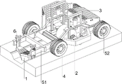
图1为本发明的立体结构示意图。Fig. 1 is a schematic diagram of the three-dimensional structure of the present invention.
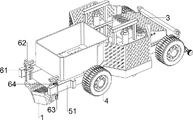
图2为本发明的部分立体结构示意图。Fig. 2 is a schematic diagram of a partial three-dimensional structure of the present invention.
图3为本发明前行机构第一种的立体结构示意图。Fig. 3 is a three-dimensional structural schematic diagram of the first type of forward traveling mechanism of the present invention.
图4为本发明前行机构第二种的立体结构示意图。Fig. 4 is a three-dimensional structural schematic diagram of the second type of forward traveling mechanism of the present invention.
图5为本发明刮平机构的立体结构示意图。Fig. 5 is a schematic perspective view of the three-dimensional structure of the scraping mechanism of the present invention.
图6为本发明刮平机构的部分立体结构示意图。Fig. 6 is a schematic diagram of a partial three-dimensional structure of the scraping mechanism of the present invention.
图7为本发明塑型机构的立体结构示意图。Fig. 7 is a three-dimensional structural schematic diagram of the molding mechanism of the present invention.
图8为本发明塑型机构的第一种部分立体结构示意图。Fig. 8 is a schematic diagram of the first partial three-dimensional structure of the molding mechanism of the present invention.
图9为本发明塑型机构的第二种部分立体结构示意图。Fig. 9 is a schematic diagram of the second partial three-dimensional structure of the molding mechanism of the present invention.
图10为本发明塑型机构的第三种部分立体结构示意图。Fig. 10 is a schematic diagram of the third partial three-dimensional structure of the shaping mechanism of the present invention.
图11为本发明投料机构的立体结构示意图。Fig. 11 is a schematic perspective view of the three-dimensional structure of the feeding mechanism of the present invention.
图12为本发明投料机构的部分立体结构示意图。Fig. 12 is a schematic diagram of a partial three-dimensional structure of the feeding mechanism of the present invention.
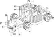
图13为本发明放置机构第一种的立体结构示意图。Fig. 13 is a schematic perspective view of the first type of placing mechanism of the present invention.
图14为本发明放置机构第二种的立体结构示意图。Fig. 14 is a schematic perspective view of the second type of placing mechanism of the present invention.
图15为本发明覆膜机构的立体结构示意图。Fig. 15 is a schematic perspective view of the three-dimensional structure of the film covering mechanism of the present invention.
图16为本发明覆膜机构的部分立体结构示意图。Fig. 16 is a schematic diagram of a partial three-dimensional structure of the film covering mechanism of the present invention.
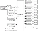
图17为本发明的电路框图。Fig. 17 is a circuit block diagram of the present invention.
图18为本发明的电路原理图。Fig. 18 is a schematic circuit diagram of the present invention.
附图标记中:1-刮板,2-塑形模具,3-控制箱,4-轮胎,5-前行机构,51-第一安装架,52-第一转轴,53-第二安装架,54-伺服电机,55-第一皮带,6-刮平机构,61-第一导套,62-第一滑动架,63-第一电动推杆,64-第一距离传感器,7-塑型机构,71-第三安装架,72-护栏,73-第二滑动架,74-第二电动推杆,75-第二距离传感器,76-连接架,77-第四安装架,78-振动电机,79-第一开关,710-第二开关,8-投料机构,81-储料桶,82-第二转轴,83-分料板,84-第二皮带,9-放置机构,91-第五安装架,92-放置杆,93-销钉,10-覆膜机构,1001-限位杆,1002-第二导套,1003-第三滑动架,1004-复位弹簧,1005-夹杆,1006-滚轮,1007-第三皮带。Among the reference signs: 1-scraper, 2-shaping mold, 3-control box, 4-tire, 5-forward travel mechanism, 51-the first mounting frame, 52-the first rotating shaft, 53-the second mounting frame , 54-servo motor, 55-the first belt, 6-scraping mechanism, 61-the first guide sleeve, 62-the first carriage, 63-the first electric push rod, 64-the first distance sensor, 7-plastic Type mechanism, 71-third mounting frame, 72-guardrail, 73-second sliding frame, 74-second electric actuator, 75-second distance sensor, 76-connecting frame, 77-fourth mounting frame, 78- Vibration motor, 79-first switch, 710-second switch, 8-feeding mechanism, 81-storage barrel, 82-second rotating shaft, 83-distributing plate, 84-second belt, 9-placement mechanism, 91 -Fifth installation frame, 92-placement rod, 93-pin, 10-film covering mechanism, 1001-limiting rod, 1002-second guide sleeve, 1003-third sliding frame, 1004-return spring, 1005-clamping rod , 1006-roller, 1007-the third belt.
具体实施方式detailed description
下面参照附图对本发明的实施例进行详细描述。Embodiments of the present invention will be described in detail below with reference to the accompanying drawings.
实施例1Example 1
一种水利工程施工用沟渠平整设备,如图1-图15所示,包括有刮板1、塑形模具2、控制箱3、轮胎4、前行机构5、刮平机构6、塑型机构7和投料机构8,前行机构5顶部右侧设有控制箱3,前行机构5上设有四个轮胎4,前行机构5左侧设有刮平机构6,刮平机构6上设有刮板1,前行机构5右侧设有塑型机构7,塑型机构7上转动式设有塑形模具2,前行机构5左侧设有投料机构8,投料机构8位于刮平机构6右侧。A kind of ditch leveling equipment for water conservancy construction, as shown in Figure 1-Figure 15, including a
前行机构5包括有第一安装架51、第一转轴52、第二安装架53、伺服电机54和第一皮带55,控制箱3与第一安装架51顶部右侧连接,第一安装架51左右两侧均转动式设有第一转轴52,第一转轴52前后两侧均与轮胎4连接,第一安装架51右侧设有第二安装架53,第二安装架53顶部后侧设有伺服电机54,右侧的第一转轴52中部与伺服电机54的输出轴之间通过皮带轮绕接有第一皮带55。The
刮平机构6包括有第一导套61、第一滑动架62、第一电动推杆63和第一距离传感器64,第一安装架51左侧前后对称设有第一导套61,第一导套61内部均滑动式设有第一滑动架62,第一滑动架62底部均与刮板1连接,第一安装架51左侧前后对称设有第一电动推杆63,第一电动推杆63位于第一导套61外侧,第一电动推杆63的伸缩杆顶部均与相邻的第一滑动架62连接,前侧的第一导套61顶部中间设有第一距离传感器64。The
塑型机构7包括有第三安装架71、护栏72、第二滑动架73、第二电动推杆74、第二距离传感器75、连接架76、第四安装架77、振动电机78、第一开关79和第二开关710,第一安装架51顶部右侧前后对称设有第三安装架71,第一安装架51顶部右侧前后对称设有护栏72,控制箱3左侧与两个护栏72连接,护栏72位于第三安装架71外侧,第三安装架71上侧中部均滑动式设有第二滑动架73,第三安装架71上侧中部均设有第二电动推杆74,第二电动推杆74位于第二滑动架73内侧,第二电动推杆74的伸缩杆顶部均与相邻的第二滑动架73连接,前侧的第三安装架71顶部左侧设有第二距离传感器75,第二滑动架73下侧中部均设有连接架76,连接架76内侧均与塑形模具2转动式连接,塑形模具2内侧中部设有第四安装架77,第四安装架77顶部中间设有振动电机78,控制箱3前侧左上部设有第一开关79和第二开关710,第二开关710位于第一开关79右侧。The molding mechanism 7 includes a
投料机构8包括有储料桶81、第二转轴82、分料板83和第二皮带84,第一安装架51顶部左侧设有储料桶81,储料桶81下部右侧转动式设有第二转轴82,第二转轴82与第一安装架51转动式连接,第二转轴82上设有分料板83,左侧的第一转轴52和第二转轴82之间前后对称通过皮带轮绕接有第二皮带84。The
当人们需要使用该沟渠平整设备时,首先人们在地面上挖一个沟槽,然后将该沟渠平整设备放置在沟槽的正上方,轮胎4与地面接触,再由人工按下电源总开关,使得该沟渠平整设备通电,第一距离传感器64和第二距离传感器75开始工作,然后人工按动一次第一开关79,第一开关79发出信号,控制模块接收到信号后控制第二电动推杆74的伸缩杆缩短,第二电动推杆74的伸缩杆带动第二滑动架73往下运动,从而带动连接架76往下运动,连接架76带动塑形模具2、第四安装架77和振动电机78往下运动,使得塑形模具2伸入沟槽内,塑形模具2与地面接触,此时,第二距离传感器75感应到与前侧的第二滑动架73顶部之间的距离小于最小预设值,第二距离传感器75发出信号,控制模块接收到信号后控制第二电动推杆74停止工作,同时控制模块控制第一电动推杆63的伸缩杆缩短,第一电动推杆63的伸缩杆带动第一滑动架62往下运动,从而带动刮板1往下运动,使得刮板1伸入沟槽内,刮板1与地面接触,此时,第一距离传感器64感应到与前侧的第一滑动架62顶部之间的距离小于最小预设值,第一距离传感器64发出信号,控制模块接收到信号后控制第一电动推杆63停止工作,然后将制作好的混凝土倒入储料桶81中,分料板83会将混凝土挡住,再按动一次第二开关710,第二开关710发出信号,控制模块接收到信号后控制伺服电机54工作,同时控制模块控制振动电机78工作,伺服电机54的输出轴通过第一皮带55能够带动右侧的第一转轴52转动,从而带动右侧的轮胎4转动,使得该沟渠平整设备往左移动,从而带动左侧的轮胎4和左侧的第一转轴52转动,轮胎4在地面上滚动,此时刮板1和塑形模具2往左运动,刮板1能够将泥土往左推出,从而在地面上开出一道沟渠,同时,左侧的第一转轴52通过第二皮带84能够带动第二转轴82转动,从而带动分料板83转动,分料板83能够将混凝土间歇性的传输至开好的沟渠内,塑形模具2在开好的沟渠内滚动,从而将混凝土挤压铺平,振动电机78工作会发生震动,带动塑形模具2稍微的震动,加强铺平的效果,护栏72能够避免混凝土飞溅出来,当人们不需要使用该沟渠平整设备时,再按动一次第二开关710,第二开关710发出信号,控制模块接收到信号后控制伺服电机54停止工作,同时控制模块控制振动电机78停止工作,此时该沟渠平整设备停止移动,然后再按动一次第一开关79,第一开关79发出信号,控制模块接收到信号后控制第二电动推杆74的伸缩杆伸长,第二电动推杆74的伸缩杆带动第二滑动架73往上运动复位,从而带动连接架76往上运动复位,连接架76带动塑形模具2、第四安装架77和振动电机78往上运动复位,使得塑形模具2与地面分离,此时,第二距离传感器75感应到与前侧的第二滑动架73顶部之间的距离大于最大预设值,第二距离传感器75发出信号,控制模块接收到信号后控制第二电动推杆74停止工作,同时控制模块控制第一电动推杆63伸长,第一电动推杆63的伸缩杆带动第一滑动架62往上运动复位,从而带动刮板1往上运动复位,使得刮板1与地面分离,此时,第一距离传感器64感应到与前侧的第一滑动架62顶部之间的距离大于最大预设值,第一距离传感器64发出信号,控制模块接收到信号后控制第一电动推杆63停止工作,然后人工按下电源总开关,使得该沟渠平整设备断电,第一距离传感器64和第二距离传感器75停止工作。When people need to use the ditch leveling equipment, first people dig a ditch on the ground, then place the ditch leveling equipment directly above the ditch, the
实施例2Example 2
在实施例1的基础之上,如图1、图2、图13、图14、图15和图16所示,还包括有放置机构9,放置机构9包括有第五安装架91、放置杆92和销钉93,第一安装架51顶部右侧前后对称设有第五安装架91,第五安装架91上部之间放置有放置杆92,前侧的第五安装架91顶部放置有销钉93,销钉93与放置杆92接触。On the basis of
还包括有覆膜机构10,覆膜机构10包括有限位杆1001、第二导套1002、第三滑动架1003、复位弹簧1004、夹杆1005、滚轮1006和第三皮带1007,第二滑动架73下部右侧均设有限位杆1001,第一安装架51前后两侧右部均设有第二导套1002,第二导套1002上均滑动式设有第三滑动架1003,第三滑动架1003顶部与相邻的限位杆1001接触,第三滑动架1003上部均绕有复位弹簧1004,复位弹簧1004的两端分别与第二导套1002和第三滑动架1003连接,第三滑动架1003下部右侧之间转动式设有两根夹杆1005,第三滑动架1003下部右侧均转动式设有滚轮1006,滚轮1006位于夹杆1005右下侧,上侧的夹杆1005前后两侧与相邻的滚轮1006内侧之间均通过皮带轮绕接有第三皮带1007。Also includes a
当人们需要使用该沟渠平整设备时,可以将销钉93往上拔出,然后将放置杆92取出,再将一卷塑料薄膜放置在第五安装架91内侧上部之间,然后将放置杆92放回原位,使得放置杆92穿过塑料薄膜中间,然后再将销钉93放回原位,从而固定放置杆92的位置,避免放置杆92掉落至地面,然后将塑料薄膜的一端拉出,再将其穿过夹杆1005之间,然后固定在地面上,当第二滑动架73往下运动时,带动限位杆1001往下运动,限位杆1001挤压第三滑动架1003往下运动,复位弹簧1004压缩,第三滑动架1003带动夹杆1005和滚轮1006往下运动,使得滚轮1006与地面接触,该沟渠平整设备往左移动时,带动塑料薄膜往左运动,滚轮1006在地面上滚动,滚轮1006通过第三皮带1007能够带动上侧的夹杆1005转动,从而将塑料薄膜往右拉出,塑料薄膜在放置杆92上转动,使得塑料薄膜能够将开好的沟渠顶部盖住,避免混凝土被太阳直晒发生干裂,而且也能避免树叶等杂物沾在混凝土上,当该沟渠平整设备停止移动时,塑料薄膜不再转动,然后人工将多余的塑料薄膜切断,再将地面上的塑料薄膜固定住即可,当第二滑动架73往上运动复位时,带动限位杆1001往上运动复位,限位杆1001与第三滑动架1003分离,复位弹簧1004恢复原状,带动第三滑动架1003往上运动复位,第三滑动架1003带动夹杆1005和滚轮1006往上运动复位,使得滚轮1006与地面分离,如此往复,当塑料薄膜用完之后,可以将销钉93往上拔出,然后将放置杆92取出,再对塑料薄膜进行更换,更换好之后,将放置杆92放回原位,再将销钉93放回原位即可。When people need to use the ditch leveling equipment, the
如图17和图18所示,控制箱3内包括有开关电源、控制模块和电源模块,开关电源为整个沟渠平整设备供电,电源模块上通过线路连接有电源总开关,控制模块和电源模块通过电性连接,控制模块上连接有DS1302时钟电路和24C02电路,第一距离传感器64、第二距离传感器75、第一开关79和第二开关710均与控制模块通过电性连接,伺服电机54、第一电动推杆63、振动电机78和第二电动推杆74均与控制模块通过外围电路连接。As shown in Figures 17 and 18, the
上述实施例,只是本发明的较佳实施例,并非用来限制本发明实施范围,故凡以本发明权利要求所述内容所做的等效变化,均应包括在本发明权利要求范围之内。The foregoing embodiments are only preferred embodiments of the present invention, and are not intended to limit the scope of the present invention, so all equivalent changes made with the contents of the claims of the present invention should be included within the scope of the claims of the present invention .
Claims (8)
Priority Applications (1)
| Application Number | Priority Date | Filing Date | Title |
|---|---|---|---|
| CN202210835006.5A CN115584702A (en) | 2022-07-16 | 2022-07-16 | Irrigation canals and ditches for hydraulic engineering construction level equipment |
Applications Claiming Priority (1)
| Application Number | Priority Date | Filing Date | Title |
|---|---|---|---|
| CN202210835006.5A CN115584702A (en) | 2022-07-16 | 2022-07-16 | Irrigation canals and ditches for hydraulic engineering construction level equipment |
Publications (1)
| Publication Number | Publication Date |
|---|---|
| CN115584702A true CN115584702A (en) | 2023-01-10 |
Family
ID=84771147
Family Applications (1)
| Application Number | Title | Priority Date | Filing Date |
|---|---|---|---|
| CN202210835006.5A Pending CN115584702A (en) | 2022-07-16 | 2022-07-16 | Irrigation canals and ditches for hydraulic engineering construction level equipment |
Country Status (1)
| Country | Link |
|---|---|
| CN (1) | CN115584702A (en) |
Cited By (1)
| Publication number | Priority date | Publication date | Assignee | Title |
|---|---|---|---|---|
| CN119195072A (en) * | 2024-11-29 | 2024-12-27 | 山东省方圆经纬设计集团有限公司 | A ditch reinforcement device for land reclamation |
-
2022
- 2022-07-16 CN CN202210835006.5A patent/CN115584702A/en active Pending
Cited By (1)
| Publication number | Priority date | Publication date | Assignee | Title |
|---|---|---|---|---|
| CN119195072A (en) * | 2024-11-29 | 2024-12-27 | 山东省方圆经纬设计集团有限公司 | A ditch reinforcement device for land reclamation |
Similar Documents
| Publication | Publication Date | Title |
|---|---|---|
| CN113335887A (en) | Water turning device for bean curd production | |
| CN212763986U (en) | A circular automatic production line cloth machine troweling device | |
| CN102990847B (en) | Fully automatic mold opening and closing for steam-heated and water-cooled foam molding machines | |
| CN211334344U (en) | Plastic injection mold convenient to clear up waste material | |
| CN209493797U (en) | An integrated device for semi-rigid base material paving without vertical formwork | |
| CN204977429U (en) | High -efficient automatic pipe -expanding machine of tubular product | |
| CN112757467A (en) | Equipment is pour to concrete prefabricated part | |
| CN108621288A (en) | A kind of sign pressing device for tile cutting machine | |
| CN207808021U (en) | A kind of slip casting machine switching mechanism | |
| CN218111145U (en) | Excess material cleaning equipment for producing cement electric poles | |
| CN118342636A (en) | A recycled concrete drainage pipe and a preparation device thereof | |
| CN117697948A (en) | Concrete member preparation equipment | |
| CN204278172U (en) | A kind of scraper | |
| CN203510724U (en) | Eraser transfer-printing production line | |
| CN210507447U (en) | Tool for paving asphalt concrete impervious core wall dam | |
| CN108501183B (en) | Cement fence forming device | |
| CN220162745U (en) | Brick mould permeates water | |
| CN209615848U (en) | A kind of asphalt mixture forming device | |
| CN110761321A (en) | Square cloth machine | |
| CN202097965U (en) | A plastic molding machine | |
| CN207643389U (en) | A kind of semidry method gypsum lath automatic production line | |
| CN215589456U (en) | A forming device for preparation of assembled light wall | |
| CN216299778U (en) | Rubber mixing machine | |
| CN207997412U (en) | A kind of hollow brick production mold automated packing device | |
| CN216831549U (en) | Automatic net laying device for producing assembly type building materials |
Legal Events
| Date | Code | Title | Description |
|---|---|---|---|
| PB01 | Publication | ||
| PB01 | Publication | ||
| SE01 | Entry into force of request for substantive examination | ||
| SE01 | Entry into force of request for substantive examination |