CN115582566A - Manufacturing method of large jaw crusher rear wall - Google Patents
Manufacturing method of large jaw crusher rear wall Download PDFInfo
- Publication number
- CN115582566A CN115582566A CN202211344884.3A CN202211344884A CN115582566A CN 115582566 A CN115582566 A CN 115582566A CN 202211344884 A CN202211344884 A CN 202211344884A CN 115582566 A CN115582566 A CN 115582566A
- Authority
- CN
- China
- Prior art keywords
- plate
- plates
- rib
- rear wall
- manufacturing
- Prior art date
- Legal status (The legal status is an assumption and is not a legal conclusion. Google has not performed a legal analysis and makes no representation as to the accuracy of the status listed.)
- Pending
Links
Images


Classifications
-
- B—PERFORMING OPERATIONS; TRANSPORTING
- B23—MACHINE TOOLS; METAL-WORKING NOT OTHERWISE PROVIDED FOR
- B23B—TURNING; BORING
- B23B31/00—Chucks; Expansion mandrels; Adaptations thereof for remote control
- B23B31/02—Chucks
-
- B—PERFORMING OPERATIONS; TRANSPORTING
- B23—MACHINE TOOLS; METAL-WORKING NOT OTHERWISE PROVIDED FOR
- B23K—SOLDERING OR UNSOLDERING; WELDING; CLADDING OR PLATING BY SOLDERING OR WELDING; CUTTING BY APPLYING HEAT LOCALLY, e.g. FLAME CUTTING; WORKING BY LASER BEAM
- B23K37/00—Auxiliary devices or processes, not specially adapted for a procedure covered by only one of the other main groups of this subclass
- B23K37/04—Auxiliary devices or processes, not specially adapted for a procedure covered by only one of the other main groups of this subclass for holding or positioning work
- B23K37/0426—Fixtures for other work
Landscapes
- Engineering & Computer Science (AREA)
- Mechanical Engineering (AREA)
- Physics & Mathematics (AREA)
- Optics & Photonics (AREA)
- Crushing And Grinding (AREA)
Abstract
本发明专利涉及到的是一种大型颚式破碎机后墙的制作方法,该装置壳体主要由两块连接板、多块中间板、两块中间肋板、一块斜板,两块外部筋板等钢板零件组成,所述制作方法包括:步骤一,平台划线;步骤二,装配中间板;步骤三,装配连接板;步骤四,装配斜板部件;步骤五,斜板部件与总体装配。本发明采取了平台划线控制精度、加放合适的焊接收缩余量等工艺措施,从而取得了提高颚式破碎机后墙的装焊质量的良好成果。
The patent of the present invention relates to a method for making the back wall of a large jaw crusher. The manufacturing method includes: Step 1, marking the platform; Step 2, assembling the middle plate; Step 3, assembling the connecting plate; Step 4, assembling the inclined plate parts; Step 5, assembling the inclined plate parts and the overall . The invention adopts technological measures such as control precision of platform scribing and adding appropriate welding shrinkage allowance, thereby achieving good results in improving the welding quality of the rear wall of the jaw crusher.
Description
技术领域technical field
本发明涉及到一种颚式破碎机部件的装焊方法,具体涉及一种颚式破碎机后墙的制作方法,属于颚式破碎机制作技术领域。The invention relates to a method for assembling and welding parts of a jaw crusher, in particular to a method for manufacturing a rear wall of a jaw crusher, and belongs to the technical field of jaw crusher manufacturing.
背景介绍background introduction
颚式破碎机俗称颚破,又名老虎口,主要由前墙、后墙、动颚等部件组成破碎腔,模拟动物的两颚运动完成物料破碎作业的破碎机,结构简单,工作可靠,广泛运用于矿山冶炼、建材、公路、铁路、水利化工等行业中各种矿石与大块物料的破碎。后墙是组成颚式破碎机重要的组成部件之一,为了保证有着足够的强度和刚度以承受破碎时反作用于破碎机上的力,所以后墙制作普遍使用厚板,导致焊接量大,焊接热输入变大,并且焊接要求较高,焊后尺寸不好控制易变形,其制造的重点和难点在于:The jaw crusher is commonly known as the jaw crusher, also known as the tiger's mouth. It is mainly composed of the front wall, the rear wall, the movable jaw and other components. It is used in the crushing of various ores and bulk materials in mining smelting, building materials, roads, railways, water conservancy and chemical industries. The rear wall is one of the important components of the jaw crusher. In order to ensure sufficient strength and rigidity to withstand the force that reacts on the crusher during crushing, thick plates are commonly used in the production of the rear wall, resulting in a large amount of welding and welding heat. The input becomes larger, and the welding requirements are higher, and the size after welding is not easy to control and easy to deform. The key points and difficulties of its manufacturing are:
1、后墙板材均是普通碳钢,厚板居多,最大板厚为120mm,容易产生较大的焊接热输入,容易变形,焊接工艺难度较大。1. The rear wall plates are all ordinary carbon steel, mostly thick plates, the maximum plate thickness is 120mm, which is prone to large welding heat input and deformation, and the welding process is difficult.
2、后墙两连接板板零件较大,与中间板装焊主要集中在中间部位,两端容易变形。2. The two connecting plates of the rear wall are relatively large, and the welding with the middle plate is mainly concentrated in the middle part, and the two ends are easily deformed.
3、后墙中所述斜板,与中间板形成角度,并且角度要求严格,不好控制。3. The sloping plate in the rear wall forms an angle with the middle plate, and the angle is strictly required, which is difficult to control.
4、由于后墙零件板厚差异较大,焊接后结构存在较大的焊接应力,对焊缝抗疲劳寿命有较大的影响。4. Due to the large difference in plate thickness of the rear wall parts, there is a large welding stress in the structure after welding, which has a great impact on the fatigue life of the weld.
发明内容Contents of the invention
本发明针对后墙的制造难点,提出一种大型颚式破碎机后墙的制作方法,能够克服焊接难度大,焊后尺寸变形,提高后墙整体的焊接质量。Aiming at the difficulty in manufacturing the rear wall, the present invention proposes a method for manufacturing the rear wall of a large jaw crusher, which can overcome the difficulty of welding and the dimensional deformation after welding, and improve the overall welding quality of the rear wall.
本发明是通过以下技术方案实现的:The present invention is achieved through the following technical solutions:
一种大型颚式破碎机后墙的制作方法,所述后墙至少包括多块中间板、两块中间肋板、两块连接板、两块外部筋板和一块斜板,其特点征在于,所述制作方法的具体步骤如下:A method for making the rear wall of a large jaw crusher, the rear wall at least includes a plurality of middle plates, two middle ribs, two connecting plates, two outer ribs and one slanting plate, characterized in that, The concrete steps of described preparation method are as follows:
步骤一,平台划线Step 1, draw a line on the platform
1.1、检验平台的水平度,确保该平台在宽度3米、长度5米的范围内水平度误差≤2mm;1.1. Check the levelness of the platform to ensure that the levelness error of the platform is ≤2mm within the range of 3 meters in width and 5 meters in length;
1.2、在所述平台上划线,按照所述后墙的结构划出第一中间板、第二中间板和第三中间板的安装线和尺寸线,且所述第一中间板和第三中间板的安装线互相平行、所述第二中间板的安装线分别垂直于所述第一中间板和第三中间板的安装线;1.2. Draw a line on the platform, draw the installation line and dimension line of the first middle board, the second middle board and the third middle board according to the structure of the rear wall, and the first middle board and the third middle board The installation lines of the intermediate plates are parallel to each other, and the installation lines of the second intermediate plate are respectively perpendicular to the installation lines of the first intermediate plate and the third intermediate plate;
步骤二,装配中间板与中间肋板
2.1、根据平台上中间板的安装线,将三块中间板竖放在给自安装线上,并固定;2.1. According to the installation line of the middle board on the platform, place the three middle boards vertically on the self-installation line and fix them;
2.2、在所述第二中间板上划出两块平行的中间肋板的安装线;2.2. Draw the installation lines of two parallel intermediate ribs on the second intermediate plate;
2.3、将两块中间肋板2.3. Put the two middle ribs together
3.1、将两块连接板平行固定在平台上,并分别在连接板上划出各中间板的安装线,尺寸偏差≤1mm;3.2、安装第一连接板和第二连接板,并用点焊使连接板与加固;3.1. Fix the two connecting plates in parallel on the platform, and draw the installation lines of each intermediate plate on the connecting plates respectively. The size deviation is ≤1mm; 3.2. Install the first connecting plate and the second connecting plate, and use spot welding to make them Connection plate and reinforcement;
步骤四,斜板部件安装:Step 4, installation of inclined plate components:
4.1、在斜板上分别划出第一筋板和第二筋板的安装线,且第一筋板的安装线和第二筋板的安装线互相平行;4.1. Draw the installation lines of the first rib and the second rib on the inclined plate respectively, and the installation line of the first rib and the installation line of the second rib are parallel to each other;
4.2将第一筋板和第二筋板根据各自筋板的安装线位置固定在斜板上,并固定,构成斜板部件;4.2 Fix the first rib and the second rib on the inclined plate according to the installation line position of the respective rib, and fix them to form the inclined plate components;
步骤五,斜板部件与整体装配Step 5, Inclined plate components and overall assembly
5.1、将所述的斜板部件安装在第三中间板的下方,且两侧分别与两连接板相连,并固定;5.1. Install the inclined plate part under the third middle plate, and connect and fix the two connecting plates on both sides;
步骤六,整体焊接Step six, overall welding
将上述各板焊接固定,并将第四中间板固定在所述第一中间板和第二中间板之间,使所述第一中间板、第二中间板、第三中间板和第四中间板与两连接板形式封闭空间。Fix the above plates by welding, and fix the fourth middle plate between the first middle plate and the second middle plate, so that the first middle plate, the second middle plate, the third middle plate and the fourth middle plate The space is closed in the form of a plate and two connecting plates.
为保证后墙壳体内部焊接,将中间板零件4最后安装,安装完后进行焊接即可。In order to ensure the internal welding of the rear wall shell, the middle plate part 4 is finally installed, and can be welded after installation.
步骤一中所述的划线要求是指:The marking requirements mentioned in Step 1 refer to:
a、所有中心线尺寸误差≤0.5mm;a. The size error of all centerlines is ≤0.5mm;
b、各位置线尺寸误差≤1mm;b. The size error of each position line is ≤1mm;
c、隔板之间尺寸加放2mm收缩余量;c. Add 2mm shrinkage allowance between the partitions;
步骤二中所述的中间板安装时,板之间的尺寸加放2mm收缩余量,最大尺寸误差≤2mm;When installing the intermediate board mentioned in
步骤三种所述的连接板和中间板焊接时需要碳刨清根。所述的碳刨清根指的是利用碳极和金属之间产生高温电流,把金属加热到熔化状态,同时利用压缩空气的高速气流把这些熔化金属吹掉,以达到清除缺陷。When welding the connecting plate and the intermediate plate described in step three, carbon planing is required. The carbon planing refers to the use of a high-temperature current between the carbon pole and the metal to heat the metal to a molten state, and at the same time use the high-speed airflow of compressed air to blow off the molten metal to remove defects.
本发明提出的一种颚式破碎机后墙的制作方法主要解决了由于后墙零件大并且板厚导致其焊接量大导致其变形难以控制的问题,并且通过加放合适的焊接收缩余量以及合理的调整装配顺序,使得工序条理分明、制作容易、焊后效果较好。本发明所述大型颚式破碎机后墙的制作方法采取了反变形,调整装配顺序,平台、零件划线装配等工艺措施,保证了尺寸的准确,满足了后墙的质量要求。The method for making the rear wall of a jaw crusher proposed by the present invention mainly solves the problem that the deformation of the rear wall is difficult to control due to the large amount of welding due to the large parts of the rear wall and the thickness of the plate, and by adding a suitable welding shrinkage allowance and Reasonably adjust the assembly sequence, so that the process is well-organized, easy to manufacture, and the effect after welding is better. The manufacturing method of the large-scale jaw crusher rear wall of the present invention adopts technological measures such as anti-deformation, adjustment of assembly sequence, platform and part marking assembly, etc., which ensures the accuracy of the size and meets the quality requirements of the rear wall.
附图说明Description of drawings
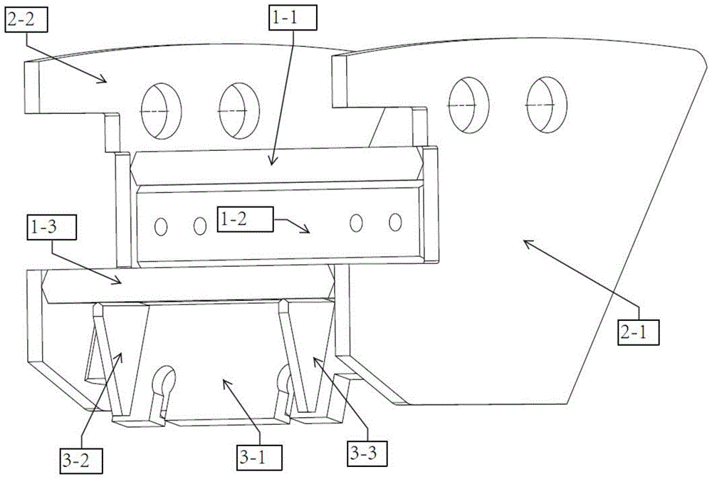
图1为后墙总成示意图。Figure 1 is a schematic diagram of the rear wall assembly.
图2为平台划线示意图。Figure 2 is a schematic diagram of platform marking.
图3为后墙的立体图。Fig. 3 is a perspective view of the rear wall.
图中:第一中间板1-1、第二中间板1-2、第三中间板1-3、第一中间肋板1-4、第二中间肋板1-5、第一连接板2-1、第二连接板2-2、斜板3-1、第一筋板3-2、第二筋板3-3、第四中间板4。In the figure: the first middle plate 1-1, the second middle plate 1-2, the third middle plate 1-3, the first middle rib 1-4, the second middle rib 1-5, the first connecting plate 2 -1. The second connecting plate 2-2, the inclined plate 3-1, the first rib plate 3-2, the second rib plate 3-3, and the fourth intermediate plate 4.
具体实施方式detailed description
下面结合附图和具体的实施例对本发明做进一步阐述,但不能以此来限制本发明的保护范围。The present invention will be further described below in conjunction with the accompanying drawings and specific embodiments, but the protection scope of the present invention cannot be limited by this.
本发明提供一种工艺制作方法,用以制造大型颚式破碎机后墙,请参阅图1。所述后墙包括多块中间板、两块中间肋板、两块连接板、两块外部筋板、一块斜板等钢板组成,其中,中间板位于两块连接板之间,两块筋板用于支撑中间板和斜板,所述斜板位于两连接板中间,中间板的下方,请参阅图1。The present invention provides a manufacturing method for manufacturing the rear wall of a large jaw crusher, please refer to FIG. 1 . The rear wall consists of a plurality of middle plates, two middle ribs, two connecting plates, two outer ribs, a slanted plate and other steel plates, wherein the middle plate is located between the two connecting plates, and the two ribs Used to support the middle plate and the inclined plate, the inclined plate is located in the middle of the two connecting plates, below the middle plate, please refer to Figure 1.
以下通过实施例详细说明本发明所述大型颚式破碎机后墙的制作方法,本实施例中,所述制作方法的具体步骤如下:The manufacturing method of the rear wall of the large jaw crusher of the present invention is described in detail below through the examples. In the present embodiment, the specific steps of the manufacturing method are as follows:
步骤一,平台划线Step 1, draw a line on the platform
1.1、所述大型颚式破碎机后墙的装配制作过程在装配专用平台上进行,而该平台的水平度将直接影响零件的加工余量以及形位公差,因此在装配划线前必须检查平台的水平度,保证所述平台在宽度3米,长度5米的范围内水平度误差≤2mm;1.1. The assembly process of the rear wall of the large jaw crusher is carried out on a special assembly platform, and the levelness of the platform will directly affect the machining allowance and shape tolerance of the parts, so the platform must be checked before assembly and marking The levelness of the platform shall ensure that the levelness error of the platform within the range of 3 meters in width and 5 meters in length is ≤ 2mm;
1.2、在所述平台上划线,按照所述后墙的结构划出第一中间板1-1、第二中间板1-2和第三中间板1-3的安装线和尺寸线,且所述第一中间板1-1和第三中间板1-3的安装线互相平行、所述第二中间板1-2的安装线分别垂直于所述第一中间板1-1和第三中间板1-3的安装线,见图2,划线应该达到以下尺寸要求:1.2. Draw a line on the platform, draw the installation line and dimension line of the first middle plate 1-1, the second middle plate 1-2 and the third middle plate 1-3 according to the structure of the rear wall, and The installation lines of the first middle board 1-1 and the third middle board 1-3 are parallel to each other, and the installation lines of the second middle board 1-2 are respectively perpendicular to the first middle board 1-1 and the third middle board 1-1. The installation line of the middle plate 1-3, see Figure 2, the marking line should meet the following size requirements:
a、所有中心线的尺寸误差≤0.5mm,a. The dimensional error of all centerlines is ≤0.5mm,
b、各位置线尺寸误差≤1mm,b. The size error of each position line is ≤1mm,
c、根据对后墙图纸研究,为保证焊后因焊接、预热、火工校正等原因造成的收缩变形,加放2mm的焊接收缩余量。c. According to the research on the drawings of the back wall, in order to ensure the shrinkage and deformation caused by welding, preheating, pyrotechnic correction and other reasons after welding, a welding shrinkage allowance of 2 mm is added.
步骤二,装配中间板与中间肋板见图1
2.1、根据平台划好的安装线将中间板1-1、1-2、1-3竖放在平台上,用角尺测量保证垂直度,装配并用点焊加固;2.1. Put the intermediate plates 1-1, 1-2, 1-3 vertically on the platform according to the installation line drawn by the platform, measure with a square to ensure the verticality, assemble and reinforce with spot welding;
2.2、在第三中间板1-3上按照尺寸划出中间肋板1-4、1-5的安装线并安装,点焊加固;2.2. On the third intermediate plate 1-3, draw out the installation lines of the intermediate rib plates 1-4 and 1-5 according to the size and install them, and reinforce them by spot welding;
步骤三,装配连接板Step 3, assemble the connection board
3.1、将第一连接板2-1用“马”固定在平台上,并划出中间板组合部件的安装线,尺寸偏差≤1mm;3.2、安装第一连接板2-1和第二连接板2-2,并用点焊加固,保证两连接板的开档尺寸;3.1. Fix the first connecting plate 2-1 on the platform with a "horse", and draw the installation line of the intermediate plate assembly parts, the size deviation is ≤ 1mm; 3.2. Install the first connecting plate 2-1 and the second connecting plate 2-2, and reinforced by spot welding to ensure the opening size of the two connecting plates;
步骤四,斜板部件安装Step 4, install the inclined plate components
4.1、将斜板与两块外部筋板制作成斜板部件,在斜板3-1上分别划出第一筋板3-2和第二筋板3-3的安装线;4.1. Make the inclined plate and two external ribs into inclined plate parts, and draw the installation lines of the first rib 3-2 and the second rib 3-3 on the inclined plate 3-1;
4.2、将第一筋板3-2和第二筋板3-3根据各自筋板的安装线位置固定在斜板3-1上,并用点焊加固防止尺寸变形;4.2. Fix the first rib plate 3-2 and the second rib plate 3-3 on the inclined plate 3-1 according to the installation line positions of the respective rib plates, and reinforce them with spot welding to prevent dimensional deformation;
步骤五,斜板部件与整体装配Step 5, Inclined plate components and overall assembly
5.1、将所述的斜板部件安装在第三中间板1-3的下方,且两侧分别与两连接板相连,斜板角度要求严格,需要制作角度相同的样板贴合装配来保证装配尺寸以及斜板角度。5.1. Install the sloping plate part below the third middle plate 1-3, and connect the two connecting plates on both sides respectively. The angle of the sloping plate is strictly required, and it is necessary to make a model with the same angle to fit and assemble to ensure the assembly size and the slope angle.
步骤六,整体焊接Step six, overall welding
将以上安装好的部件进行整体焊接,焊接前需安装钢管加强防止连接板变形,焊接按照图纸焊接焊缝增强量焊接后进行火工校正。The above-installed parts are welded as a whole. Before welding, steel pipes need to be installed to strengthen the connecting plate to prevent deformation of the connecting plate. After welding, the welding seam reinforcement should be welded according to the drawings, and then pyrotechnic correction should be carried out.
步骤七,安装中间板零件4Step 7, install the middle plate part 4
为保证后墙壳体内部可以焊接,将将第四中间板4固定在所述第一中间板1-1和第二中间板1-2之间,使所述第一中间板1-1、第二中间板1-2、第三中间板1-3和第四中间板4与两连接板形式封闭空间,安装完后进行焊接,完成制作。In order to ensure that the inside of the rear wall housing can be welded, the fourth intermediate plate 4 will be fixed between the first intermediate plate 1-1 and the second intermediate plate 1-2, so that the first intermediate plate 1-1, The second middle plate 1-2, the third middle plate 1-3 and the fourth middle plate 4 form a closed space with the two connecting plates, and welding is performed after installation to complete the fabrication.
尽管已经示出和描述了本发明的实施例,对于本领域的普通技术人员而言,可以理解在不脱离本发明的原理和精神的情况下可以对这些实施例进行多种变化、修改、替换和变型,本发明的范围由所附权利要求及其等同物限定。Although the embodiments of the present invention have been shown and described, those skilled in the art can understand that various changes, modifications and substitutions can be made to these embodiments without departing from the principle and spirit of the present invention. and modifications, the scope of the invention is defined by the appended claims and their equivalents.
Claims (8)
Priority Applications (1)
| Application Number | Priority Date | Filing Date | Title |
|---|---|---|---|
| CN202211344884.3A CN115582566A (en) | 2022-10-31 | 2022-10-31 | Manufacturing method of large jaw crusher rear wall |
Applications Claiming Priority (1)
| Application Number | Priority Date | Filing Date | Title |
|---|---|---|---|
| CN202211344884.3A CN115582566A (en) | 2022-10-31 | 2022-10-31 | Manufacturing method of large jaw crusher rear wall |
Publications (1)
| Publication Number | Publication Date |
|---|---|
| CN115582566A true CN115582566A (en) | 2023-01-10 |
Family
ID=84782518
Family Applications (1)
| Application Number | Title | Priority Date | Filing Date |
|---|---|---|---|
| CN202211344884.3A Pending CN115582566A (en) | 2022-10-31 | 2022-10-31 | Manufacturing method of large jaw crusher rear wall |
Country Status (1)
| Country | Link |
|---|---|
| CN (1) | CN115582566A (en) |
Cited By (1)
| Publication number | Priority date | Publication date | Assignee | Title |
|---|---|---|---|---|
| CN116833694A (en) * | 2023-07-06 | 2023-10-03 | 中船海洋动力部件有限公司 | Repair and cutting method of guide plate after complete machining of marine diesel engine frame |
Citations (3)
| Publication number | Priority date | Publication date | Assignee | Title |
|---|---|---|---|---|
| CN103506763A (en) * | 2012-12-28 | 2014-01-15 | 沪东重机有限公司 | Manufacturing method of welding type cylinder block of marine diesel engine |
| CN108127284A (en) * | 2017-12-29 | 2018-06-08 | 中船海洋动力部件有限公司 | Assembly method before a kind of marine diesel rack weldering |
| CN109396762A (en) * | 2018-11-09 | 2019-03-01 | 中船海洋动力部件有限公司 | The assembly method of marine diesel exhaust gas recirculation device shell |
-
2022
- 2022-10-31 CN CN202211344884.3A patent/CN115582566A/en active Pending
Patent Citations (3)
| Publication number | Priority date | Publication date | Assignee | Title |
|---|---|---|---|---|
| CN103506763A (en) * | 2012-12-28 | 2014-01-15 | 沪东重机有限公司 | Manufacturing method of welding type cylinder block of marine diesel engine |
| CN108127284A (en) * | 2017-12-29 | 2018-06-08 | 中船海洋动力部件有限公司 | Assembly method before a kind of marine diesel rack weldering |
| CN109396762A (en) * | 2018-11-09 | 2019-03-01 | 中船海洋动力部件有限公司 | The assembly method of marine diesel exhaust gas recirculation device shell |
Cited By (1)
| Publication number | Priority date | Publication date | Assignee | Title |
|---|---|---|---|---|
| CN116833694A (en) * | 2023-07-06 | 2023-10-03 | 中船海洋动力部件有限公司 | Repair and cutting method of guide plate after complete machining of marine diesel engine frame |
Similar Documents
| Publication | Publication Date | Title |
|---|---|---|
| CN113718648B (en) | Steel-concrete combined tower segment with special-shaped curve structure and manufacturing process | |
| CN102277825A (en) | Steel truss bridge and method for fabricating same | |
| CN114346596B (en) | Manufacturing method of concave hyperbolic three-dimensional pipe truss and double box columns | |
| CN110695558B (en) | Manufacturing method of suspension bridge main cable saddle | |
| CN115582638A (en) | Large-scale super-long titanium alloy special-shaped thin shell precision casting and processing and welding deformation control technology | |
| CN110480197A (en) | Manufacturing method of super-large thick plate cross box member | |
| CN102744580B (en) | Furnace body manufacturing method of polycrystalline ingot furnace | |
| CN107972476A (en) | Radiator frame assembly | |
| CN104234212A (en) | Socket and spigot type light steel frame connecting joint and construction method thereof | |
| CN103878498B (en) | The preparation method of marine diesel welded type cylinder block | |
| CN109183741B (en) | Manufacturing and using method of special-shaped template for tail water flow channel of power plant | |
| CN112688462A (en) | Wind turbine base and manufacturing method thereof | |
| CN103506763A (en) | Manufacturing method of welding type cylinder block of marine diesel engine | |
| CN203730225U (en) | Connecting device of sectional type blades | |
| CN110802339B (en) | Machining method for node of box-shaped steel structure shaped like Chinese character' mi | |
| CN206524362U (en) | A kind of new-energy automobile aluminum alloy battery casing | |
| CN203448717U (en) | Locating and welding tool for threaded sleeve of power battery pack | |
| CN201677819U (en) | A side door side impact sensor bracket sheet metal structure | |
| CN116122425A (en) | Adjustable node and method for large-scale container modularized steel structure | |
| CN113832281A (en) | Factory production and installation method of smelting reduction furnace | |
| CN201028274Y (en) | A high-pressure gas storage tank shell | |
| CN116275651A (en) | How to make a common base | |
| CN207657597U (en) | A kind of radiator frame assembly | |
| CN221567941U (en) | Vertical fossil fragments positioning fixture of arc glass curtain wall | |
| CN223282082U (en) | Transparent light tunnel secondary lining trolley template |
Legal Events
| Date | Code | Title | Description |
|---|---|---|---|
| PB01 | Publication | ||
| PB01 | Publication | ||
| SE01 | Entry into force of request for substantive examination | ||
| SE01 | Entry into force of request for substantive examination | ||
| WD01 | Invention patent application deemed withdrawn after publication |
Application publication date: 20230110 |
|
| WD01 | Invention patent application deemed withdrawn after publication |