Disclosure of Invention
The present invention has been made in view of the above problems, and aims to provide an antenna adjustment arrangement that overcomes or at least partially solves the above problems.
The invention provides an antenna adjusting device, comprising:
a chassis;
the first connecting shaft is vertically arranged and is rotatably connected to the case;
the horizontal adjusting mechanism is positioned in the case and is in transmission connection with the first connecting shaft;
one end part of the first fixing rod is fixedly connected with the first connecting shaft;
the antenna is rotatably connected with the other end of the first fixing rod, and the horizontal adjusting mechanism drives the first connecting shaft to rotate in the horizontal direction when acting so as to adjust the azimuth angle of the antenna in the horizontal direction;
the second connecting shaft is vertically arranged and is rotationally connected to the case;
the linear bearing is sleeved on the second connecting shaft;
the pitching adjusting mechanism is positioned in the case and is connected with the linear bearing;
one end of the second fixing rod is rotatably connected with the linear bearing, and the other end of the second fixing rod is fixed with the antenna; wherein,
and when the pitching adjusting mechanism acts, the linear bearing is driven to do linear motion in the vertical direction so as to adjust the pitching angle of the antenna in the vertical direction.
Optionally, the horizontal adjustment mechanism includes:
the first rotary motion output unit is fixed on the case;
and the transmission unit is in transmission connection with the output shaft of the first rotary motion output unit and the first connecting shaft respectively and is used for transmitting the rotating force output by the first rotary motion output unit to the first connecting shaft.
Optionally, the transmission unit includes:
a first sprocket coaxially fixed with an output shaft of the first rotary motion output unit;
the second chain wheel is sleeved on the first connecting shaft and is coaxially fixed with the first connecting shaft;
and the chain is meshed with the first chain wheel and the second chain wheel respectively, and the first connecting shaft is driven to rotate by the chain when the first rotary motion output unit works.
Optionally, the first rotational motion output unit includes a stepping motor and a speed reducer stacked above the stepping motor, the stepping motor is fixed to the chassis, an output shaft of the stepping motor is fixedly connected to the speed reducer, and an output shaft of the speed reducer is coaxially fixed to the first sprocket.
Optionally, the pitch adjustment mechanism comprises:
the electric cylinder is fixed in the case;
the connecting block is fixedly connected with an output shaft of the electric cylinder, the connecting block is sleeved outside the linear bearing and movably connected with the linear bearing, a limiting groove for limiting the connecting block is formed in the linear bearing, and the connecting block keeps in a static state when the linear bearing rotates horizontally.
Optionally, the side of the case is further provided with a plurality of heat dissipation holes for dissipating heat of the electric cylinder and the stepping motor.
Optionally, the device further comprises a controller located in the case, the controller is electrically connected with the electric cylinder and the stepping motor respectively, and the controller comprises a wireless communication module for remotely controlling the electric cylinder and the stepping motor to act.
Optionally, the outer side of the linear bearing is further provided with a rotating block, and the rotating block is rotatably connected with the second fixing rod.
Optionally, the device further comprises a connecting plate for mounting the antenna, one end of the connecting plate is rotatably connected with the other end of the first fixing rod, and the middle of the connecting plate and the other end of the second fixing rod are fixed through a locking screw.
Optionally, the chassis is of a sheet metal structure.
Compared with the prior art, the invention comprises a case, a first connecting shaft, a horizontal adjusting mechanism, a first fixing rod, an antenna, a second connecting shaft, a linear bearing, a pitching adjusting mechanism and a second fixing rod. The first connecting shaft is vertically arranged and rotatably connected to the case, and the horizontal adjusting mechanism is located in the case and is in transmission connection with the first connecting shaft. One end of the first fixing rod is fixedly connected with the first connecting shaft, and the antenna is rotatably connected with the other end of the first fixing rod. When the horizontal adjusting mechanism acts, the first connecting shaft is driven to rotate in the horizontal direction so as to adjust the azimuth angle of the antenna in the horizontal direction. The second connecting shaft is vertically arranged and is rotatably connected to the case, and the linear bearing is sleeved on the second connecting shaft. The pitching adjusting mechanism is positioned in the case and connected with the linear bearing. One end part of the second fixing rod is rotatably connected with the linear bearing, and the other end part of the second fixing rod is fixed with the antenna. When the pitching adjusting mechanism acts, the linear bearing is driven to do linear motion in the vertical direction so as to adjust the pitching angle of the antenna in the vertical direction. The invention optimizes the network by adjusting the angles of the antenna in the horizontal direction and the vertical direction. The method has the advantages of wide application range, strong network optimization capability and the like.
The above description is only an overview of the technical solutions of the present invention, and the present invention can be implemented in accordance with the content of the description so as to make the technical means of the present invention more clearly understood, and the above and other objects, features, and advantages of the present invention will be more clearly understood.
Detailed Description
Exemplary embodiments of the present invention will be described in more detail below with reference to the accompanying drawings. While exemplary embodiments of the invention are shown in the drawings, it should be understood that the invention can be embodied in various forms and should not be limited to the embodiments set forth herein. Rather, these embodiments are provided so that this disclosure will be thorough and complete, and will fully convey the scope of the invention to those skilled in the art.
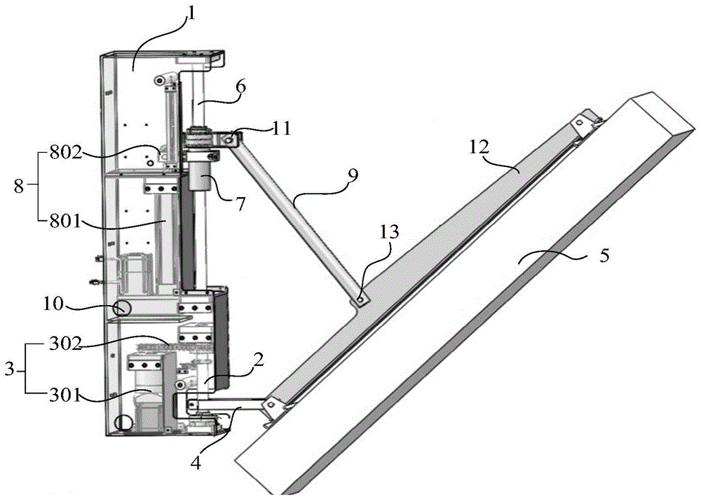
Referring to fig. 1 and 2, an embodiment of the present invention provides an antenna adjustment apparatus, which may include a chassis 1, a first connection shaft 2, a horizontal adjustment mechanism 3, a first fixing rod 4, an antenna 5, a second connection shaft 6, a linear bearing 7, a pitch adjustment mechanism 8, and a second fixing rod 9, wherein:
the first connecting shaft 2 is vertically arranged (i.e. arranged parallel to the vertical direction), and is rotatably connected to the case 1. For example, the first connecting shaft 2 may be mounted on one side of the housing 1, wherein the rotational connection is achieved by providing two mounting bearings on both ends of the first connecting shaft 2, the mounting bearings being fixed on the housing 1. In one example, in order to improve the structural stability of the case 1, the case 1 is of a sheet metal structure, that is, the case 1 is manufactured by sheet metal processing, and in order to be suitable for long-term use of the device in an outdoor environment, the case 1 has a waterproof function.
The horizontal adjusting mechanism 3 is positioned in the case 1 and is in transmission connection with the first connecting shaft 2. One end of the first fixing rod 4 is fixedly connected with the first connecting shaft 2. The antenna 5 is rotatably connected to the other end of the first fixing rod 4. When the horizontal adjusting mechanism 3 acts, the first connecting shaft 2 is driven to rotate in the horizontal direction, and when the first rotating shaft rotates, the first fixing rod 4 is driven to rotate so as to adjust the azimuth angle of the antenna 5 in the horizontal direction. In one example, the azimuth angle adjustment range of the antenna 5 in the horizontal direction by the horizontal adjustment mechanism 3 may be 0 to 120 °. Based on the azimuth angle adjusting range, the azimuth angle adjusting requirement in daily network optimization operation can be met.
The second connecting shaft 6 is vertically arranged (i.e. arranged parallel to the vertical direction), and is rotatably connected to the case 1, and the linear bearing 7 is sleeved on the second connecting shaft 6. In one example, the central axis of the first connecting shaft 2 and the central axis of the second connecting shaft 6 are collinear, that is, the second connecting shaft 6 is also installed at the side of the case 1 and is located right above the first connecting shaft 2. Wherein the rotational connection is realized by providing two mounting bearings at both ends of the second connecting shaft 6, the mounting bearings being fixed to the cabinet 1. The first connecting shaft 2, the second connecting shaft 6, the first fixing rod 4 and the second fixing rod 9 are positioned in the same plane. The pitching adjusting mechanism 8 is positioned in the case 1 and connected with the linear bearing 7. One end of the second fixing rod 9 is rotatably connected to the linear bearing 7, and the other end is fixed to the antenna 5. When the pitching adjusting mechanism 8 acts, the linear bearing 7 is driven to do linear motion in the vertical direction, so as to adjust the pitching angle of the antenna 5 in the vertical direction. In one example, the pitch angle of the antenna 5 in the vertical direction by the pitch adjustment mechanism 8 may be adjusted in a range of 0 to 45 °. Based on the pitching angle adjusting range, the pitching angle adjusting requirement in daily network optimization operation can be met.
Referring to fig. 1, in an alternative embodiment of the invention, the horizontal adjustment mechanism 3 may include a first rotary motion output unit 301 and a transmission unit 302, wherein the first rotary motion output unit 301 is used for outputting rotary motion, and the first rotary motion output unit 301 is fixed on the chassis 1. The transmission unit 302 is in transmission connection with the output shaft of the first rotary motion output unit 301 and the first connecting shaft 2, so that the transmission unit 302 can be used to transmit the rotary force output by the first rotary motion output unit 301 to the first connecting shaft 2.
An alternative inventive embodiment, shown with reference to fig. 2, the transfer unit 302 may include a first sprocket 3021, a second sprocket 3022, and a chain 3023. The first sprocket 3021 is coaxially fixed with the output shaft of the first rotational motion output unit 301 (i.e., the central axis of the first sprocket 3021 and the central axis of the output shaft of the first rotational motion output unit 301 are collinear, and the first sprocket 3021 is fixedly connected with the output shaft thereof). The second chain wheel 3022 is sleeved on the first connecting shaft 2, and is coaxially fixed to the first connecting shaft 2 (i.e., the central axis of the second chain wheel 3022 is collinear with the central axis of the first connecting shaft 2, and the second chain wheel 3022 is fixedly connected to the first connecting shaft 2). The chain 3023 meshes with a first sprocket 3021 and a second sprocket 3022, respectively, wherein during operation of the first rotary motion output unit 301 the first sprocket 3021 is driven in rotation, so that the first connecting shaft 2 is rotated by the chain 3023 meshing with the first sprocket 3021.
In another alternative embodiment of the invention, the transfer unit 302 may include a first pulley, a second pulley, and an engagement belt. The connection relationship among the first pulley, the second pulley, and the meshing belt is described with reference to the connection relationship among the first sprocket 3021, the second sprocket 3022, and the chain 3023.
As an alternative embodiment of the invention, referring to fig. 2, the first rotary motion output unit 301 may include a stepping motor 3011 and a speed reducer 3012 stacked above the stepping motor 3011, the stepping motor 3011 is fixed on the chassis 1, an output shaft of the stepping motor 3011 is fixedly connected to the speed reducer 3012, and an output shaft of the speed reducer 3012 is coaxially fixed to the first sprocket 3021. The speed reducer 3012 is added to the stepping motor 3011 to reduce the rotation speed of the stepping motor 3011 and increase the torque of the stepping motor 3011, so that the stepping motor 3011 can rotate with a small torque and a large load. Further, the decelerator 3012 having a self-locking function may be employed, so that the first rotary motion output unit 301 has excellent operation stability and operation safety even in an outdoor environment of a bad weather.
An alternative embodiment of the invention, as shown in fig. 1 and 2, the pitch adjustment mechanism 8 may include an electric cylinder 801 and a connection block 802, wherein the electric cylinder 801 is fixed in the case 1. The connecting block 802 is fixedly connected with an output shaft of the electric cylinder 801, wherein the connecting block 802 is sleeved outside the linear bearing 7 and movably connected with the linear bearing 7, a limiting groove for limiting the connecting block 802 is formed in the linear bearing 7, and when the linear bearing 7 rotates horizontally, the connecting block 802 keeps in a static state. That is, when the first connecting shaft 2 rotates and the second fixing rod 9 drives the linear bearing 7 to rotate synchronously, the connecting block 802 fixedly connected to the electric cylinder 801 does not operate. When the pitch angle of the antenna 5 is adjusted, and the output shaft of the electric cylinder 801 extends out or retracts, correspondingly, the connecting block 802 drives the linear bearing 7 to synchronously ascend or descend due to the upper and lower limiting effects of the limiting groove. Thereby changing the angle between the second fixing rod 9 and the linear bearing 7 for the purpose of pitch angle adjustment of the antenna 5.
Referring to fig. 1, a plurality of heat dissipation holes 10 are further formed in a side portion of the case 1 for dissipating heat of the electric cylinder 801 and the stepping motor 3011, wherein the heat dissipation holes 10 may be in a regular shape such as a circle and easy to process. Moreover, a person skilled in the art may determine the number of the heat dissipation holes 10 according to actual requirements, which is not limited herein. The heat dissipation holes 10 can prolong the service life of components such as the electric cylinder 801, the speed reducer 3012 and the stepping motor 3011.
In an alternative embodiment of the invention, the apparatus may further include a controller located in the chassis 1. The controller is respectively electrically connected with the electric cylinder 801 and the stepping motor 3011. The controller comprises a wireless communication module for remotely controlling the electric cylinder 801 and the stepping motor 3011 to act. In one example, the motor in the electric cylinder 801 may also be a stepping motor, and the controller may control the rotation speed and direction of the stepping motor 3011 through a transmission pulse and a direction signal received remotely. Because the antenna 5 is usually installed on a communication base station with a higher height, the angle of the antenna 5 can be adjusted remotely and automatically, so that the related personnel can be prevented from working high above the ground (especially, the network optimization adjustment can not be carried out manually under the continuous severe weather condition), the safety factor of the network optimization during working is improved, and the adjustment precision of the antenna 5 is controllable. Therefore, the method has the advantages of strong optimization capability, high safety, high adjustment precision, labor cost saving and the like. For example, the above-described embodiments of the invention may be widely applied to the rapid adjustment of the antenna 5 of a communication base station in remote areas and/or in areas with heavy personnel.
In an alternative embodiment of the invention, in order to further improve the structural stability of the device, referring to fig. 1 and 2, a rotating block 11 is further disposed at an outer side of the linear bearing 7, and the rotating block 11 is rotatably connected to the second fixing rod 9. The rotating block 11 is used for enlarging the connection area between the rotating block and the second fixing rod 9, so that the linear bearing 7 with a smaller pipe diameter can be selected, and the product cost is reduced.
An alternative embodiment of the invention is shown in fig. 1, and the apparatus further includes a connecting plate 12 for mounting the antenna 5, and in order to ensure the mounting stability of the antenna 5, the connecting plate 12 may be of a sheet metal structure. Wherein, one end of the connecting plate 12 is rotatably connected with the other end of the first fixing rod 4, and the middle of the connecting plate 12 is fixed with the other end of the second fixing rod 9 by a locking screw 13.
In the embodiments of the present invention, a baffle may be additionally disposed on the side of the case 1 where the first connecting shaft 2 is installed according to an actual scene, and the stepping motor 3011, the electric cylinder 801, the speed reducer 3012, and other components are isolated from the external environment by the baffle, so as to form an operating environment with better sealing performance, thereby improving the service life of the components.
In summary, the present invention discloses an antenna adjusting apparatus, which includes a case 1, a first connecting shaft 2, a horizontal adjusting mechanism 3, a first fixing rod 4, an antenna 5, a second connecting shaft 6, a linear bearing 7, a pitching adjusting mechanism 8, and a second fixing rod 9. The first connecting shaft 2 is vertically arranged and rotatably connected to the case 1, and the horizontal adjusting mechanism 3 is located in the case 1 and is in transmission connection with the first connecting shaft 2. One end of the first fixing rod 4 is fixedly connected to the first connecting shaft 2, and the antenna 5 is rotatably connected to the other end of the first fixing rod 4. When the horizontal adjusting mechanism 3 acts, the first connecting shaft 2 is driven to rotate in the horizontal direction, so as to adjust the azimuth angle of the antenna 5 in the horizontal direction. The second connecting shaft 6 is vertically arranged and rotatably connected to the case 1, and the linear bearing 7 is sleeved on the second connecting shaft 6. The pitch adjusting mechanism 8 is positioned in the case 1 and connected with the linear bearing 7. One end of the second fixing lever 9 is rotatably connected to the linear bearing 7 and the other end is fixed to the antenna 5. When the pitching adjusting mechanism 8 acts, the linear bearing 7 is driven to do linear motion in the vertical direction, so as to adjust the pitching angle of the antenna 5 in the vertical direction. The present invention performs network optimization by adjusting the angles in the horizontal direction and the vertical direction of the antenna 5. The method has the advantages of wide application range, strong network optimization capability and the like.
The embodiments in the present specification are described in a progressive manner, each embodiment focuses on differences from other embodiments, and the same and similar parts among the embodiments are referred to each other.
As readily imaginable to the person skilled in the art: any combination of the above embodiments is possible, and thus any combination between the above embodiments is an embodiment of the present invention, but the present disclosure is not necessarily detailed herein for reasons of space.
In the description provided herein, numerous specific details are set forth. However, it is understood that embodiments of the invention may be practiced without these specific details. In some instances, well-known methods, structures and techniques have not been shown in detail in order not to obscure an understanding of this description.
Similarly, it should be appreciated that in the foregoing description of exemplary embodiments of the invention, various features of the invention are sometimes grouped together in a single embodiment, figure, or description thereof for the purpose of streamlining the invention and aiding in the understanding of one or more of the various inventive aspects.
Furthermore, those skilled in the art will appreciate that while some embodiments described herein include some features included in other embodiments, rather than other features, combinations of features of different embodiments are meant to be within the scope of the invention and form different embodiments. For example, in the claims, any of the claimed embodiments may be used in any combination.