CN115570831A - Hydraulic press for forming powder product - Google Patents
Hydraulic press for forming powder product Download PDFInfo
- Publication number
- CN115570831A CN115570831A CN202211272827.9A CN202211272827A CN115570831A CN 115570831 A CN115570831 A CN 115570831A CN 202211272827 A CN202211272827 A CN 202211272827A CN 115570831 A CN115570831 A CN 115570831A
- Authority
- CN
- China
- Prior art keywords
- support frame
- fixedly connected
- rod
- motor
- frame
- Prior art date
- Legal status (The legal status is an assumption and is not a legal conclusion. Google has not performed a legal analysis and makes no representation as to the accuracy of the status listed.)
- Pending
Links
Images



Classifications
-
- B—PERFORMING OPERATIONS; TRANSPORTING
- B30—PRESSES
- B30B—PRESSES IN GENERAL
- B30B11/00—Presses specially adapted for forming shaped articles from material in particulate or plastic state, e.g. briquetting presses, tabletting presses
- B30B11/02—Presses specially adapted for forming shaped articles from material in particulate or plastic state, e.g. briquetting presses, tabletting presses using a ram exerting pressure on the material in a moulding space
- B30B11/04—Presses specially adapted for forming shaped articles from material in particulate or plastic state, e.g. briquetting presses, tabletting presses using a ram exerting pressure on the material in a moulding space co-operating with a fixed mould
-
- B—PERFORMING OPERATIONS; TRANSPORTING
- B30—PRESSES
- B30B—PRESSES IN GENERAL
- B30B15/00—Details of, or accessories for, presses; Auxiliary measures in connection with pressing
- B30B15/30—Feeding material to presses
- B30B15/302—Feeding material in particulate or plastic state to moulding presses
- B30B15/304—Feeding material in particulate or plastic state to moulding presses by using feed frames or shoes with relative movement with regard to the mould or moulds
-
- B—PERFORMING OPERATIONS; TRANSPORTING
- B30—PRESSES
- B30B—PRESSES IN GENERAL
- B30B15/00—Details of, or accessories for, presses; Auxiliary measures in connection with pressing
- B30B15/32—Discharging presses
Landscapes
- Engineering & Computer Science (AREA)
- Mechanical Engineering (AREA)
- Press Drives And Press Lines (AREA)
Abstract
本发明公开了一种粉末制品成型液压机,涉及粉末制品成型技术领域。包括第一支撑架和第二支撑架,第一支撑架连接有两个支撑杆,第一支撑架插设有两个第一丝杆,第一丝杆插设于支撑杆,第一丝杆插设于第二支撑架,第一支撑架连接有两个第一电机,第一电机输出轴与第一丝杆通过皮带连接,第二支撑架内设有定量进料下料机构,第一支撑架内设有压料机构和顶起机构,第一支撑架固定连接有支架,支架设有推料机构。本发明方便脱模,并且能够实现自动定量进料和自动挤压成型。

The invention discloses a powder product forming hydraulic press, which relates to the technical field of powder product forming. It includes a first support frame and a second support frame, the first support frame is connected with two support rods, the first support frame is inserted with two first screw rods, the first screw rods are inserted into the support rods, the first screw rods Inserted in the second support frame, the first support frame is connected with two first motors, the output shaft of the first motor is connected with the first screw rod through a belt, the second support frame is equipped with a quantitative feeding and unloading mechanism, the first The supporting frame is provided with a pressing mechanism and a jacking mechanism, the first supporting frame is fixedly connected with a bracket, and the bracket is provided with a pushing mechanism. The invention is convenient for demoulding, and can realize automatic quantitative feeding and automatic extrusion molding.
Description
技术领域technical field
本发明涉及粉末制品成型技术领域,特别涉及一种粉末制品成型液压机。The invention relates to the technical field of powder product molding, in particular to a powder product molding hydraulic press.
背景技术Background technique
粉末制品液压机是指通过模具将金属粉末、陶瓷粉末以及其他合金粉末压缩成相应所要求的形状与规格。The powder product hydraulic press refers to compressing metal powder, ceramic powder and other alloy powder into the corresponding required shape and specification through the mold.
公告号为CN207207209U的中国实用新型专利申请公开了一种全自动粉末液压机,主要包括充液桶、主缸、并紧螺母、锁紧螺母、直线导套、送料板、压制调整限位柱、拉杆、加料限位块、移粉装置、脱模限位块、底座、上梁、活动梁、导柱、阴模活动板、调节螺母、下模固定板和顶缸。该方案能够使粉末制品上、中、下密度均匀。The Chinese utility model patent application with the notification number CN207207209U discloses a fully automatic powder hydraulic machine, which mainly includes a liquid-filled barrel, a main cylinder, a parallel nut, a lock nut, a linear guide bush, a feeding plate, a pressing and adjusting limit column, and a tie rod. , Feeding limit block, powder shifting device, demoulding limit block, base, upper beam, movable beam, guide column, female mold movable plate, adjusting nut, lower mold fixed plate and jacking cylinder. This solution can make the upper, middle and lower density of the powder product uniform.
但是上述方案不方便进行脱模和自动定量进料,工作效率较低。However, the above scheme is inconvenient for demoulding and automatic quantitative feeding, and the work efficiency is low.
发明内容Contents of the invention
本发明要解决的技术问题为:提供一种能够自动定量进料、自动成型与脱模的粉末制品成型液压机。The technical problem to be solved by the present invention is to provide a powder product forming hydraulic press capable of automatic quantitative feeding, automatic forming and demoulding.
针对上述技术问题,本发明采用的技术方案为:一种粉末制品成型液压机,包括第一支撑架和第二支撑架,所述第一支撑架固定连接有两个支撑杆,所述第一支撑架插设有两个第一丝杆,两个所述第一丝杆与两个所述支撑杆一一对应,所述第一丝杆插设于所述支撑杆且两者之间转动连接,所述第一丝杆插设于所述第二支撑架且两者之间螺纹连接,所述第一支撑架固定连接有两个第一电机,两个所述第一电机与两个所述第一丝杆一一对应,所述第一电机输出轴与所述第一丝杆通过皮带连接,所述第二支撑架内设有定量进料下料机构,所述第一支撑架内设有压料机构和顶起机构,所述第一支撑架固定连接有支架,所述支架设有推料机构。In view of the above technical problems, the technical solution adopted in the present invention is: a powder product forming hydraulic press, comprising a first support frame and a second support frame, the first support frame is fixedly connected with two support rods, and the first support frame Two first screw rods are inserted into the frame, and the two first screw rods correspond to the two support rods one by one. The first screw rods are inserted into the support rods and are rotatably connected between them. , the first screw rod is inserted into the second support frame and screwed between the two, the first support frame is fixedly connected with two first motors, and the two first motors are connected to the two The first screw rods are in one-to-one correspondence, the output shaft of the first motor is connected to the first screw rod through a belt, the second support frame is provided with a quantitative feeding and unloading mechanism, and the first support frame A pressing mechanism and a jacking mechanism are provided, the first support frame is fixedly connected with a bracket, and the bracket is provided with a pushing mechanism.
进一步的,所述定量进料下料机构包括第二电机,所述第二电机输出轴固定连接有第二丝杆,所述第二丝杆套设有滑动架且两者之间螺纹连接,所述滑动架插设于所述第二支撑架且两者之间滑动连接,所述滑动架固定连接有送料筒,所述送料筒底部铰接有挡板,所述挡板与所述第二支撑架贴合。Further, the quantitative feeding and unloading mechanism includes a second motor, the output shaft of the second motor is fixedly connected with a second screw rod, and the second screw rod is covered with a sliding frame and is threadedly connected between the two, The sliding frame is inserted into the second supporting frame and is slidably connected between the two, the sliding frame is fixedly connected with a feeding cylinder, the bottom of the feeding cylinder is hinged with a baffle plate, and the baffle plate is connected to the second support frame. The support frame fits snugly.
进一步的,所述第二支撑架固定连接有进料筒。Further, the second support frame is fixedly connected with a feeding cylinder.
进一步的,所述滑动架插设有导向杆且两者之间滑动连接,所述导向杆与所述第二支撑架固定连接。Further, the sliding frame is inserted with a guide rod and is slidably connected therebetween, and the guide rod is fixedly connected with the second support frame.
进一步的,所述压料机构包括第三电机和第三支撑架,所述第三电机与所述第三支撑架固定连接,所述第三支撑架与所述第一支撑架固定连接,所述第三电机输出轴固定连接有转动块,所述转动块与所述第三支撑架转动连接,所述转动块周侧开设有滑轨,所述滑轨内滑动连接有滑动杆,所述滑动杆固定连接有压杆,所述压杆插设于所述第三支撑架且两者之间滑动连接,所述压杆固定连接有压板。Further, the pressing mechanism includes a third motor and a third support frame, the third motor is fixedly connected to the third support frame, the third support frame is fixedly connected to the first support frame, and the The output shaft of the third motor is fixedly connected with a rotating block, and the rotating block is rotationally connected with the third support frame. A slide rail is provided around the rotating block, and a sliding rod is slidingly connected inside the sliding rail. The sliding bar is fixedly connected with a pressing bar, and the pressing bar is inserted into the third support frame and slidably connected between the two, and the pressing bar is fixedly connected with a pressing plate.
进一步的,所述顶起机构包括第四电机,所述第四电机与所述第一支撑架固定连接,所述第四电机输出轴固定连接有转盘,所述第一支撑架插设有第一齿条且两者之间滑动连接,所述转盘开设有卡槽,所述转盘通过卡槽与所述第一齿条啮合,所述第一齿条固定连接有顶杆,所述顶杆固定连接有支撑板,所述支撑板与所述压板对应。Further, the jacking mechanism includes a fourth motor, the fourth motor is fixedly connected to the first support frame, the output shaft of the fourth motor is fixedly connected to a turntable, and the first support frame is inserted with a second A rack and sliding connection between the two, the turntable is provided with a slot, the turntable engages with the first rack through the slot, the first rack is fixedly connected with a push rod, and the push rod A support plate is fixedly connected, and the support plate corresponds to the pressing plate.
进一步的,所述推料机构包括第五电机,所述第五电机与所述第一支撑架固定连接,所述第五电机输出轴固定连接有第一转动杆,所述第一转动杆铰接有第二转动杆,所述第二转动杆铰接有滑动块,所述滑动块插设于所述支架且两者之间滑动连接,所述滑动块固定连接有转轴,所述支架插设有转筒且两者之间转动连接,所述转轴与所述转筒啮合,所述转筒固定连接有齿轮,所述齿轮啮合有第二齿条,所述第二齿条插设于所述支架且两者之间滑动连接,所述第二齿条固定连接有推板,所述推板插设于所述第一支撑架且两者之间滑动连接。Further, the pushing mechanism includes a fifth motor, the fifth motor is fixedly connected to the first support frame, the output shaft of the fifth motor is fixedly connected to a first rotating rod, and the first rotating rod is hinged There is a second rotating rod, the second rotating rod is hinged with a sliding block, the sliding block is inserted in the bracket and is slidably connected between the two, the sliding block is fixedly connected with a rotating shaft, and the bracket is inserted with The rotating cylinder is connected in rotation between the two, the rotating shaft is meshed with the rotating cylinder, the rotating cylinder is fixedly connected with a gear, and the gear is engaged with a second rack, and the second rack is inserted in the The bracket is slidably connected between the two, the second rack is fixedly connected with a push plate, and the push plate is inserted into the first support frame and slidably connected between the two.
进一步的,所述转轴外侧绕设有螺旋杆,所述转筒内侧开设有螺旋槽,所述螺旋杆与所述螺旋槽啮合。Further, a screw rod is wound around the outer side of the rotating shaft, and a helical groove is formed in the inner side of the drum, and the helical rod is engaged with the helical groove.
本发明与现有技术相比的有益效果是:(1)本发明通过设置第二支撑架、第一电机、第一丝杆、第二电机、第二丝杆、滑动架、送料筒、挡板和进料筒,当送料筒的顶部开口与进料筒的底部开口对准时,即可通过进料筒向送料筒内定量加料,当送料筒底部的挡板与第二支撑架脱离接触后,送料筒内的物料即可掉落至支撑板上,能够实现自动定量上料和下料,不用工作人员反复进行操作,灵活方便。Compared with the prior art, the present invention has the beneficial effects as follows: (1) the present invention is provided with the second support frame, the first motor, the first screw rod, the second motor, the second screw rod, the sliding frame, the feeding cylinder, the stopper Plate and feeding barrel, when the top opening of the feeding barrel is aligned with the bottom opening of the feeding barrel, quantitative feeding can be made into the feeding barrel through the feeding barrel, when the baffle at the bottom of the feeding barrel is out of contact with the second support frame , the material in the feeding barrel can drop to the support plate, which can realize automatic quantitative loading and unloading, without repeated operations by the staff, which is flexible and convenient.
(2)本发明通过设置第三电机、第三支撑架、转动块、滑轨、滑动杆、压杆、压板、第四电机、转盘、第一齿条、顶杆和支撑板,通过压板将支撑板上的粉末压制成饼状,能够自动将粉末压制成型并且将压制成型后的粉末顶起至第一支撑架的出口,自动化程度高。(2) The present invention sets the third motor, the third support frame, the rotating block, the slide rail, the sliding rod, the pressure rod, the pressure plate, the fourth motor, the turntable, the first rack, the ejector rod and the support plate, and through the pressure plate the The powder on the support plate is pressed into a cake shape, which can automatically press the powder and lift the pressed powder to the outlet of the first support frame, with a high degree of automation.
(3)本发明通过设置第五电机、第一转动杆、第二转动杆、滑动块、转轴、转筒、齿轮、第二齿条和推板,通过推板的运动将支撑板上压制成型后的粉末从第一支撑板上的出口推出,实现压制成型后的粉末的自动脱模,提高工作效率。(3) In the present invention, the fifth motor, the first rotating rod, the second rotating rod, the sliding block, the rotating shaft, the rotating cylinder, the gear, the second rack and the push plate are arranged, and the support plate is pressed and formed by the movement of the push plate. The finished powder is pushed out from the outlet on the first support plate, which realizes the automatic demoulding of the pressed powder and improves the working efficiency.
附图说明Description of drawings
图1是本发明一种粉末制品成型液压机整体结构示意图。Fig. 1 is a schematic diagram of the overall structure of a powder product forming hydraulic press according to the present invention.
图2是图1第二视角结构示意图。FIG. 2 is a schematic structural diagram of a second viewing angle in FIG. 1 .
图3是第二支撑架以及与之连接的零件结构示意图。Fig. 3 is a structural schematic diagram of the second support frame and parts connected thereto.
图4是定量进料下料机构示意图。Fig. 4 is a schematic diagram of the quantitative feeding and unloading mechanism.
图5是第二支撑架和进料筒连接结构示意图。Fig. 5 is a schematic diagram of the connection structure between the second support frame and the feeding cylinder.
图6是第一支撑架内部结构示意图。Fig. 6 is a schematic diagram of the internal structure of the first support frame.
图7是压料机构示意图。Fig. 7 is a schematic diagram of a pressing mechanism.
图8是顶起机构示意图。Figure 8 is a schematic diagram of the jacking mechanism.
图9是转盘和第一齿条连接结构示意图。Fig. 9 is a schematic diagram of the connection structure between the turntable and the first rack.
图10是转盘结构示意图。Fig. 10 is a structural schematic diagram of the turntable.
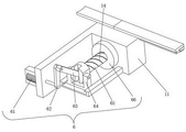
图11是推料机构示意图。Figure 11 is a schematic diagram of the pushing mechanism.
图12是图11第二视角结构示意图。FIG. 12 is a schematic structural diagram of the second viewing angle of FIG. 11 .
附图标号:1、第一支撑架;2、第二支撑架;3、定量进料下料机构;31、第二电机;32、第二丝杆;33、滑动架;34、送料筒;35、挡板;4、压料机构;41、第三电机;42、第三支撑架;43、转动块;44、滑轨;45、滑动杆;46、压杆;47、压板;5、顶起机构;51、第四电机;52、转盘;53、第一齿条;54、卡槽;55、顶杆;56、支撑板;6、推料机构;61、第五电机;62、第一转动杆;63、第二转动杆;64、滑动块;65、转轴;66、转筒;67、齿轮;68、第二齿条;69、推板;7、支撑杆;8、第一丝杆;9、第一电机;10、皮带;11、支架;12、进料筒;13、导向杆;14、螺旋杆;15、螺旋槽。Reference numerals: 1, the first support frame; 2, the second support frame; 3, the quantitative feeding and unloading mechanism; 31, the second motor; 32, the second screw rod; 33, the sliding frame; 34, the feeding cylinder; 35, baffle plate; 4, pressing mechanism; 41, the third motor; 42, the third support frame; 43, rotating block; 44, slide rail; 45, sliding rod; 46, pressing rod; 47, pressing plate; 5, Jacking mechanism; 51, fourth motor; 52, turntable; 53, first rack; 54, slot; 55, ejector rod; 56, support plate; 6, pushing mechanism; 61, fifth motor; 62, 63, the second rotating rod; 64, sliding block; 65, rotating shaft; 66, rotating cylinder; 67, gear; 68, the second rack; 69, push plate; 7, support rod; 8, the first 9, the first motor; 10, the belt; 11, the bracket; 12, the feeding cylinder; 13, the guide rod; 14, the screw rod; 15, the spiral groove.
具体实施方式detailed description
下面结合附图并通过具体实施方式来进一步说明本发明的技术方案。The technical solutions of the present invention will be further described below in conjunction with the accompanying drawings and through specific implementation methods.
其中,附图仅用于示例性说明,表示的仅是示意图,而非实物图,不能理解为对本专利的限制;为了更好地说明本发明的实施例,附图某些部件会有省略、放大或缩小,并不代表实际产品的尺寸;对本领域技术人员来说,附图中某些公知结构及其说明可能省略是可以理解的。Wherein, the accompanying drawings are only for illustrative purposes, showing only schematic diagrams, rather than physical drawings, and should not be construed as limitations on this patent; in order to better illustrate the embodiments of the present invention, some parts of the accompanying drawings will be omitted, Enlargement or reduction does not represent the size of the actual product; for those skilled in the art, it is understandable that certain known structures and their descriptions in the drawings may be omitted.
实施例:如图1-图12所示,本实施例提出的一种粉末制品成型液压机由第一支撑架1、第二支撑架2、支撑杆7、第一丝杆8、第一电机9、皮带10、定量进料下料机构3、压料机构4、顶起机构5、支架11和推料机构6联接构成。Embodiment: As shown in Fig. 1-Fig. 12, a powder product forming hydraulic press proposed in this embodiment consists of a
如图1和图2所示,一种粉末制品成型液压机,包括第一支撑架1和第二支撑架2,第一支撑架1固定连接有两个支撑杆7,第一支撑架1插设有两个第一丝杆8,两个第一丝杆8与两个支撑杆7一一对应,第一丝杆8插设于支撑杆7且两者之间转动连接,设置的支撑杆7对第一丝杆8进行支撑,第一丝杆8插设于第二支撑架2且两者之间螺纹连接,如图3、图4和图5所示,第一支撑架1固定连接有两个第一电机9,两个第一电机9与两个第一丝杆8一一对应,第一电机9输出轴与第一丝杆8通过皮带10连接,通过皮带10连接的目的是为了保证第二支撑架2能够随着第一丝杆8的转动而正常运动,避免第一电机9与第二支撑架2产生干涉,第二支撑架2内设有定量进料下料机构3,如图6所示,第一支撑架1内设有压料机构4和顶起机构5,第一支撑架1固定连接有支架11,支架11设有推料机构6。As shown in Figures 1 and 2, a powder product molding hydraulic machine includes a
如图3、图4和图5所示,定量进料下料机构3包括第二电机31,第二电机31输出轴固定连接有第二丝杆32,第二丝杆32套设有滑动架33且两者之间螺纹连接,滑动架33插设于第二支撑架2且两者之间滑动连接,滑动架33固定连接有送料筒34,送料筒34为中空结构,送料筒34底部铰接有挡板35,挡板35与第二支撑架2贴合。As shown in Figure 3, Figure 4 and Figure 5, the quantitative feeding and unloading mechanism 3 includes a
如图3和图5所示,第二支撑架2固定连接有进料筒12,进料筒12为中空结构,并且进料筒12的底部与第二支撑架2连通,目的是为了保证进料筒12内的粉末能够进入送料筒34内。As shown in Figure 3 and Figure 5, the
如图3和图4所示,滑动架33插设有导向杆13且两者之间滑动连接,导向杆13与第二支撑架2固定连接,设置的导向杆13起到支撑作用,提高滑动架33运动过程中的稳定性。As shown in Figures 3 and 4, the
如图6和图7所示,压料机构4包括第三电机41和第三支撑架42,第三电机41与第三支撑架42固定连接,第三支撑架42与第一支撑架1固定连接,第三支撑架42对第三电机41、转动块43和压杆46进行支撑,第三电机41输出轴固定连接有转动块43,转动块43与第三支撑架42转动连接,转动块43周侧开设有滑轨44,滑轨44内滑动连接有滑动杆45,转动块43在转动过程中,通过滑轨44和滑动杆45的配合,从而控制滑动杆45能够在竖直方向上做直线运动,滑动杆45固定连接有压杆46,压杆46插设于第三支撑架42且两者之间滑动连接,压杆46固定连接有压板47,图示中压板47的形状为圆柱形。As shown in Figures 6 and 7, the
如图8、图9和图10所示,顶起机构5包括第四电机51,第四电机51与第一支撑架1固定连接,第四电机51输出轴固定连接有转盘52,第一支撑架1插设有第一齿条53且两者之间滑动连接,转盘52开设有卡槽54,转盘52通过卡槽54与第一齿条53啮合,在卡槽54的辅助下,通过转盘52的转动,能够带动第一齿条53在竖直方向上的运动,第一齿条53固定连接有顶杆55,顶杆55固定连接有支撑板56,图示中支撑板56的形状为圆柱形,支撑板56与压板47对应,支撑板56与压板47的轴线重合,保证压板47能够准确压在支撑板56上,从而将支撑板56上的粉末压制成型。As shown in Figure 8, Figure 9 and Figure 10, the
如图11和图12所示,推料机构6包括第五电机61,第五电机61与第一支撑架1固定连接,第五电机61输出轴固定连接有第一转动杆62,第一转动杆62铰接有第二转动杆63,第二转动杆63铰接有滑动块64,设置第一转动杆62和第二转动杆63的目的是为了使得第五电机61绕着一个方向转动即可实现滑动块64的往复直线运动,进而控制第二齿条68和推板69的推进和收回,不用频繁控制第五电机61正反转,方便操作,滑动块64插设于支架11且两者之间滑动连接,滑动块64固定连接有转轴65,支架11插设有转筒66且两者之间转动连接,转轴65与转筒66啮合,具体的,转轴65外侧绕设有螺旋杆14,转筒66内侧开设有螺旋槽15,螺旋杆14与螺旋槽15啮合转筒66固定连接有齿轮67,在螺旋杆14和螺旋槽15的配合下,将转轴65在水平方向上的直线运动转化为转筒66的转动,从而控制齿轮67转动,齿轮67啮合有第二齿条68,第二齿条68插设于支架11且两者之间滑动连接,第二齿条68固定连接有推板69,推板69插设于第一支撑架1且两者之间滑动连接,第一支撑架1开设有斜坡和出口,压制成型后的粉末能够被顶出至出口所在的位置,然后推板69将支撑板56上压制成型的粉末通过斜坡从第一支撑架1内推出。As shown in Figures 11 and 12, the
本发明公开的工作原理为:(1)启动第一电机9,第一电机9通过皮带10带动第一丝杆8转动,第一丝杆8转动的同时,第二支撑架2能够在水平方向上做直线运动,第二支撑架2带动送料筒34、进料筒12和第二电机31一起运动,当第二支撑架2运动到合适位置后,启动第二电机31,第二电机31输出轴带动第二丝杆32转动,第二丝杆32转动的同时,滑动架33在第二支撑架2内滑动,滑动架33带动送料筒34运动,送料筒34带动挡板35运动,挡板35与第二支撑架2底面贴合,随着送料筒34的运动,挡板35与第二支撑架2的底面脱离接触,此时送料筒34从第二支撑架2内移出,并且送料筒34内的粉末会掉落在支撑板56上,控制第二电机31反转,滑动架33带动送料筒34反向运动,当送料筒34的顶部开口与进料筒12的底部开口对准后,即可通过进料筒12向送料筒34内定量加料(此时进料筒12与送料筒34连通,向进料筒12内添加粉末,粉末即可进入送料筒34内),需要再次向支撑板56上掉落粉末时,重复上述步骤即可。The working principle disclosed in the present invention is: (1) start the first motor 9, the first motor 9 drives the first screw rod 8 to rotate through the belt 10, and while the first screw rod 8 rotates, the second support frame 2 can move in the horizontal direction do linear motion, the second support frame 2 drives the feeding cylinder 34, the feeding cylinder 12 and the second motor 31 to move together, when the second support frame 2 moves to a suitable position, start the second motor 31, and the second motor 31 outputs The shaft drives the second screw mandrel 32 to rotate, and when the second screw mandrel 32 rotates, the sliding frame 33 slides in the second support frame 2, the sliding frame 33 drives the feeding cylinder 34 to move, and the feeding cylinder 34 drives the baffle plate 35 to move, and the baffle plate 35 fits with the bottom surface of the second support frame 2, and along with the movement of the feed tube 34, the baffle plate 35 is out of contact with the bottom surface of the second support frame 2, and now the feed tube 34 is removed from the second support frame 2, and the feed tube The powder in 34 will fall on the support plate 56, control the second motor 31 to reverse, the sliding frame 33 drives the feeding cylinder 34 to move in the reverse direction, when the top opening of the feeding cylinder 34 is aligned with the bottom opening of the feeding cylinder 12 , can feed quantitatively into the feeding cylinder 34 through the feeding cylinder 12 (at this time, the feeding cylinder 12 is connected to the feeding cylinder 34, and powder is added to the feeding cylinder 12, and the powder can enter the feeding cylinder 34), and it needs to be fed again When the powder falls on the support plate 56, the above steps can be repeated.
(2)启动第三电机41,第三电机41输出轴带动转动块43转动,在滑轨44的作用下,随着转动块43的转动,滑动杆45能够在滑轨44内滑动,同时滑动杆45带动压杆46在竖直方向上运动,压杆46带动压板47运动,压板47能够将支撑板56上的粉末压制成型。(2) Start the
(3)启动第四电机51,第四电机51输出轴带动转盘52转动,在卡槽54的辅助下,转盘52带动第一齿条53在竖直方向上运动,第一齿条53带动顶杆55运动,顶杆55带动支撑板56运动,支撑板56将压制成型后的粉末向上顶出至第一支撑架1的出口所在的位置。(3) Start the
(4)启动第五电机61,第五电机61输出轴带动第一转动杆62转动,第一转动杆62带动第二转动杆63运动,第二转动杆63带动滑动块64在支架11上滑动,滑动块64带动转轴65运动,因为螺旋杆14和螺旋槽15的啮合,转轴65在水平方向上做直线运动的同时,转筒66能够转动,进而带动齿轮67转动,齿轮67带动第二齿条68运动,第二齿条68带动推板69运动,通过推板69将压制成型的粉末从第一支撑架1内推出。(4) Start the
本发明不局限上述具体实施方式,所属技术领域的技术人员从上述构思出发,不经过创造性的劳动,做出的种种变换,均落在本发明的保护范围之内。The present invention is not limited to the above-mentioned specific implementation manners, and various transformations made by those skilled in the art starting from the above-mentioned concepts without creative work all fall within the protection scope of the present invention.
Claims (8)
Priority Applications (1)
| Application Number | Priority Date | Filing Date | Title |
|---|---|---|---|
| CN202211272827.9A CN115570831A (en) | 2022-10-18 | 2022-10-18 | Hydraulic press for forming powder product |
Applications Claiming Priority (1)
| Application Number | Priority Date | Filing Date | Title |
|---|---|---|---|
| CN202211272827.9A CN115570831A (en) | 2022-10-18 | 2022-10-18 | Hydraulic press for forming powder product |
Publications (1)
| Publication Number | Publication Date |
|---|---|
| CN115570831A true CN115570831A (en) | 2023-01-06 |
Family
ID=84585540
Family Applications (1)
| Application Number | Title | Priority Date | Filing Date |
|---|---|---|---|
| CN202211272827.9A Pending CN115570831A (en) | 2022-10-18 | 2022-10-18 | Hydraulic press for forming powder product |
Country Status (1)
| Country | Link |
|---|---|
| CN (1) | CN115570831A (en) |
Citations (9)
| Publication number | Priority date | Publication date | Assignee | Title |
|---|---|---|---|---|
| KR20120010504A (en) * | 2010-07-26 | 2012-02-03 | 김경운 | Molding and Straightening Powder Press Machine |
| CN107263783A (en) * | 2017-07-31 | 2017-10-20 | 贵州荣兴新型建材科技有限公司 | Wood powder conveying device is used in Wood plastic boards production |
| CN207207209U (en) * | 2017-09-01 | 2018-04-10 | 李建国 | A kind of fully automatic powder hydraulic press |
| KR20180122825A (en) * | 2017-05-04 | 2018-11-14 | 일신테크 주식회사 | Powder Press Machine Having Servomotor Driving Mechanism |
| CN211165466U (en) * | 2019-11-05 | 2020-08-04 | 陕西匠诚工业控制系统有限公司 | A solid powder pressing machine |
| CN211222230U (en) * | 2019-11-01 | 2020-08-11 | 青岛鸣润工艺品有限公司 | High efficiency powder forming machine |
| CN112809398A (en) * | 2020-08-18 | 2021-05-18 | 连灿鑫 | Material increasing and decreasing combined machining center |
| CN215090689U (en) * | 2021-03-04 | 2021-12-10 | 江苏振宁半导体研究院有限公司 | Powder metallurgy pressing equipment convenient to maintain |
| CN114714585A (en) * | 2022-06-09 | 2022-07-08 | 通号工程局集团有限公司天津分公司 | High-speed railway accessory injection moulding device |
-
2022
- 2022-10-18 CN CN202211272827.9A patent/CN115570831A/en active Pending
Patent Citations (9)
| Publication number | Priority date | Publication date | Assignee | Title |
|---|---|---|---|---|
| KR20120010504A (en) * | 2010-07-26 | 2012-02-03 | 김경운 | Molding and Straightening Powder Press Machine |
| KR20180122825A (en) * | 2017-05-04 | 2018-11-14 | 일신테크 주식회사 | Powder Press Machine Having Servomotor Driving Mechanism |
| CN107263783A (en) * | 2017-07-31 | 2017-10-20 | 贵州荣兴新型建材科技有限公司 | Wood powder conveying device is used in Wood plastic boards production |
| CN207207209U (en) * | 2017-09-01 | 2018-04-10 | 李建国 | A kind of fully automatic powder hydraulic press |
| CN211222230U (en) * | 2019-11-01 | 2020-08-11 | 青岛鸣润工艺品有限公司 | High efficiency powder forming machine |
| CN211165466U (en) * | 2019-11-05 | 2020-08-04 | 陕西匠诚工业控制系统有限公司 | A solid powder pressing machine |
| CN112809398A (en) * | 2020-08-18 | 2021-05-18 | 连灿鑫 | Material increasing and decreasing combined machining center |
| CN215090689U (en) * | 2021-03-04 | 2021-12-10 | 江苏振宁半导体研究院有限公司 | Powder metallurgy pressing equipment convenient to maintain |
| CN114714585A (en) * | 2022-06-09 | 2022-07-08 | 通号工程局集团有限公司天津分公司 | High-speed railway accessory injection moulding device |
Similar Documents
| Publication | Publication Date | Title |
|---|---|---|
| CN212763990U (en) | A new type of powder molding machine | |
| CN111376443A (en) | A kind of auxiliary demoulding device for injection mould and its operation method | |
| CN118321544A (en) | A powder metallurgy die auxiliary forming device and use method thereof | |
| CN108637045B (en) | An automatic bending device for wire threading trough cover for easy material picking | |
| CN115771298A (en) | Tablet pressing mechanism of a rotary tablet press | |
| CN218134184U (en) | Bilateral bender of syntropy | |
| CN217775577U (en) | Automatic feeding and conveying device for machining | |
| CN211165466U (en) | A solid powder pressing machine | |
| CN119724902B (en) | Soft magnetic ferrite powder magnetic core extrusion molding machine | |
| CN118269206B (en) | Electromechanical integrated multi-station automatic brick making machine | |
| CN111761005B (en) | Spring coiling machine for spring processing | |
| CN118107130B (en) | Demolding device for injection molding machine | |
| CN222387202U (en) | Building rubbish brickmaking device | |
| CN119822025A (en) | Push-pull machine assembly line type automatic feeding and discharging equipment and method | |
| CN109774230B (en) | An automatic feeding press | |
| CN112009009A (en) | High-precision powder forming machine | |
| CN215587829U (en) | Precision casting machine | |
| CN112027584A (en) | Automatic loading attachment that anti-drop falls | |
| CN116766360A (en) | Refractory brick forming system | |
| CN209599529U (en) | A multifunctional automatic molding device | |
| CN219274233U (en) | Stamping die with direction propelling movement structure | |
| CN218656629U (en) | A kind of spring mold with broken wire structure | |
| CN222519895U (en) | Blank feeding and turning mechanism of roll forging machine | |
| CN222902438U (en) | A finished product receiving hand for a loading and unloading punching machine | |
| CN223890525U (en) | Automatic material loading silicon molybdenum goods raw materials compression molding device |
Legal Events
| Date | Code | Title | Description |
|---|---|---|---|
| PB01 | Publication | ||
| PB01 | Publication | ||
| SE01 | Entry into force of request for substantive examination | ||
| SE01 | Entry into force of request for substantive examination | ||
| RJ01 | Rejection of invention patent application after publication |
Application publication date: 20230106 |
|
| RJ01 | Rejection of invention patent application after publication |