CN115566561A - Cooling formula smart power grids switch board - Google Patents
Cooling formula smart power grids switch board Download PDFInfo
- Publication number
- CN115566561A CN115566561A CN202211344726.8A CN202211344726A CN115566561A CN 115566561 A CN115566561 A CN 115566561A CN 202211344726 A CN202211344726 A CN 202211344726A CN 115566561 A CN115566561 A CN 115566561A
- Authority
- CN
- China
- Prior art keywords
- control cabinet
- switch board
- plate
- groove
- rotating
- Prior art date
- Legal status (The legal status is an assumption and is not a legal conclusion. Google has not performed a legal analysis and makes no representation as to the accuracy of the status listed.)
- Withdrawn
Links
- 238000001816 cooling Methods 0.000 title claims abstract description 22
- 239000004744 fabric Substances 0.000 claims abstract description 24
- 238000009434 installation Methods 0.000 claims 2
- 239000000428 dust Substances 0.000 abstract description 13
- 230000000694 effects Effects 0.000 abstract description 5
- 230000001681 protective effect Effects 0.000 abstract 1
- 238000005516 engineering process Methods 0.000 description 5
- 238000012986 modification Methods 0.000 description 3
- 230000004048 modification Effects 0.000 description 3
- 230000017525 heat dissipation Effects 0.000 description 2
- 230000001360 synchronised effect Effects 0.000 description 2
- 238000004804 winding Methods 0.000 description 2
- 230000009286 beneficial effect Effects 0.000 description 1
- 238000004891 communication Methods 0.000 description 1
- 238000010586 diagram Methods 0.000 description 1
Images


Classifications
-
- H—ELECTRICITY
- H02—GENERATION; CONVERSION OR DISTRIBUTION OF ELECTRIC POWER
- H02B—BOARDS, SUBSTATIONS OR SWITCHING ARRANGEMENTS FOR THE SUPPLY OR DISTRIBUTION OF ELECTRIC POWER
- H02B1/00—Frameworks, boards, panels, desks, casings; Details of substations or switching arrangements
- H02B1/56—Cooling; Ventilation
- H02B1/565—Cooling; Ventilation for cabinets
-
- H—ELECTRICITY
- H02—GENERATION; CONVERSION OR DISTRIBUTION OF ELECTRIC POWER
- H02B—BOARDS, SUBSTATIONS OR SWITCHING ARRANGEMENTS FOR THE SUPPLY OR DISTRIBUTION OF ELECTRIC POWER
- H02B1/00—Frameworks, boards, panels, desks, casings; Details of substations or switching arrangements
- H02B1/26—Casings; Parts thereof or accessories therefor
- H02B1/28—Casings; Parts thereof or accessories therefor dustproof, splashproof, drip-proof, waterproof or flameproof
-
- H—ELECTRICITY
- H02—GENERATION; CONVERSION OR DISTRIBUTION OF ELECTRIC POWER
- H02B—BOARDS, SUBSTATIONS OR SWITCHING ARRANGEMENTS FOR THE SUPPLY OR DISTRIBUTION OF ELECTRIC POWER
- H02B1/00—Frameworks, boards, panels, desks, casings; Details of substations or switching arrangements
- H02B1/26—Casings; Parts thereof or accessories therefor
- H02B1/30—Cabinet-type casings; Parts thereof or accessories therefor
Landscapes
- Engineering & Computer Science (AREA)
- Power Engineering (AREA)
- Cooling Or The Like Of Electrical Apparatus (AREA)
Abstract
The invention discloses a cooling type intelligent power grid control cabinet, and relates to the technical field of power grid control cabinets; but the present invention includes; the control cabinet is characterized by comprising a control cabinet, wherein a protective plate is rotatably arranged on one side of the control cabinet, an electrical element is fixedly arranged in the control cabinet, and rotating plates are rotatably arranged on two sides of the control cabinet; when the temperature in the switch board is high, drive first mount through actuating mechanism and remove, first mount drives radiator fan and removes the radiating groove position, dispel the heat to the switch board inside through radiator fan, discharge the steam in the switch board, through rotating the rotor plate, the rotor plate lower extreme leaves the switch board, make the switch board lower extreme open, the radiating effect is improved, the rotor plate removes can stimulate the dustproof cloth, block part of dust through the dustproof cloth, when the temperature is not high in the switch board, the second mount drives the filter screen and removes the radiating groove position, realize the natural heat of fanning, block the dust through the filter screen, protect internal electrical components.
Description
Technical Field
The invention relates to the technical field of power grid control cabinets, in particular to a cooling type intelligent power grid control cabinet.
Background
With the industrial development of electric power, the electric power department begins to adopt a network-controlled smart grid control system to perform automatic power distribution operation. The intelligent power grid control cabinet is usually combined with various technologies, including a computer technology, an electronic automation technology, a communication technology, a network technology and the like, and the comprehensive control cabinet for the power grid is a necessary control cabinet for power distribution automation system engineering and bears the task of mutual connection between power distribution equipment and an intelligent control system;
traditional smart power grids switch board is all really seted up the heat dissipation through-hole on diapire or lateral wall to realize the air convection of switch board internal environment and external environment, reduce the temperature in the switch board, the inside temperature cooling effect of switch board is poor when the weather is overheated, and things such as outside dust enter into inside the causing of switch board and pollute moreover, influence switch board internal element's life, to above-mentioned problem, the inventor provides a cooling formula smart power grids switch board and is used for solving above-mentioned problem.
Disclosure of Invention
The problem that the service life of internal elements of the control cabinet is influenced due to the fact that the temperature cooling effect of the interior of the control cabinet is poor, and external dust and other objects enter the interior of the control cabinet to cause pollution is solved; the invention aims to provide a cooling type intelligent power grid control cabinet.
In order to solve the technical problems, the invention adopts the following technical scheme: the utility model provides a cooling formula smart power grids switch board, includes the switch board, switch board one side is rotated and is equipped with the protection shield, the switch board internal fixation is equipped with electrical components, the switch board both sides are rotated and are equipped with the rotor plate, the radiating groove has been seted up on the rotor plate, rotor plate one side slides and is equipped with first mount, the fixed a plurality of radiator fan that are equipped with on the first mount, the rotor plate opposite side slides and is equipped with the second mount, the fixed filter screen that is equipped with on the second mount, be equipped with actuating mechanism on the rotor plate, first mount and second mount equal with the radiating groove area, the rotor plate upper end is rotated with the switch board and is connected.
Preferably, a first supporting plate is fixedly arranged on each of two sides of the rotating plate, a limiting groove is formed in the upper surface of the first supporting plate, a pair of rollers is fixedly arranged at the lower ends of the first fixing frame and the second fixing frame, the rollers are located in the limiting groove, a second supporting plate is fixedly arranged on each of two sides of the rotating plate, a rotating rod is rotatably arranged on the second supporting plate, the second supporting plate is concave, one end of the rotating rod is attached to the second supporting plate, a screw is arranged on the second supporting plate in a threaded manner, the lower end of the screw is in threaded connection with one end of the rotating rod, the first supporting plate is located below the first fixing frame and the second fixing frame, and the second supporting plate is located above the first fixing frame and the second fixing frame.
Preferably, the driving mechanism includes a first mounting bracket, the first mounting bracket is fixedly provided with one side of the rotating plate, a first motor is fixedly provided on the first mounting bracket, a first bevel gear set is fixedly provided at an output end of the first motor, a first round rod is rotatably provided in the rotating plate, an upper end of the first round rod is fixedly connected with the first bevel gear set, a driving gear is fixedly provided on the first round rod, a mounting groove is formed in the rotating plate, a lower end of the first round rod is rotatably connected with an inner wall of the mounting groove, driving blocks are fixedly provided on the first mounting bracket and the second mounting bracket, the driving blocks are meshed with the driving gear, a moving block is fixedly provided on an upper surface of the driving block, the moving block is attached to an inner wall of the second supporting plate, upper and lower sides of the driving blocks are attached to an inner wall of the mounting groove, the length of the mounting groove is greater than that of the driving block, and the driving gear is located at a center position of the mounting groove.
Preferably, the control cabinet is internally and fixedly provided with a supporting block, a fixed column is fixedly arranged at the upper end of the supporting block, a pair of moving columns is arranged in the fixed column in a sliding manner, a connecting frame is fixedly arranged on one side of the rotating plate, a connecting plate is arranged on the connecting frame in a rotating manner, one side of the connecting plate is fixedly connected with one end of the moving column, the moving column is attached to the inner wall of the fixed column, a second mounting frame is fixedly arranged on the upper surface of the fixed column, a second motor is fixedly arranged on the second mounting frame, a second bevel gear set is fixedly arranged at the output end of the second motor, a pair of threaded rods are arranged in the fixed column in a rotating manner, the threaded rods are in threaded connection with the moving columns, and the end portions of the threaded rods are fixedly connected with the second bevel gear set.
Preferably, the switch board internal fixation is equipped with places the box, place and seted up the standing groove on the box, the standing groove internal rotation is equipped with rotatory roller, the winding is equipped with dustproof cloth on the rotatory roller, place box one side and seted up the spread groove, dustproof cloth one end is passed the spread groove, dustproof cloth one end and rotor plate lower extreme fixed connection, the fixed torsional spring that is equipped with in rotatory roller both ends, the torsional spring both ends are laminated with the spread groove inner wall mutually.
Compared with the prior art, the invention has the beneficial effects that:
when the temperature in the switch board is high, drive first mount through actuating mechanism and remove, first mount drives radiator fan and removes the radiating groove position, the synchronous radiating groove position that leaves of second mount, dispel the heat to the switch board inside through radiator fan, discharge the steam in the switch board, through rotating the rotor plate, the rotor plate lower extreme leaves the switch board, make the switch board lower extreme open, the radiating effect improves, the rotor plate removes can stimulate the dustproof cloth, block some dust through the dustproof cloth, when the temperature is not high in the switch board, the second mount drives the filter screen and removes the radiating groove position, block the dust through the filter screen, protect internal electrical components.
Drawings
In order to more clearly illustrate the embodiments of the present invention or the technical solutions in the prior art, the drawings used in the description of the embodiments or the prior art will be briefly described below, it is obvious that the drawings in the following description are only some embodiments of the present invention, and for those skilled in the art, other drawings can be obtained according to the drawings without creative efforts.
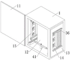
FIG. 1 is a schematic view of the structure of the present invention.
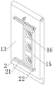
Fig. 2 is a schematic view of the rotating plate according to the present invention.
Fig. 3 is a schematic cross-sectional view of the rotating plate of the present invention.
Fig. 4 is a schematic structural diagram of the driving mechanism of the present invention.
Fig. 5 is a schematic view of a fixing post structure according to the present invention.
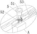
FIG. 6 is an enlarged view of the structure at A in FIG. 5 according to the present invention.
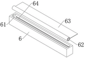
FIG. 7 is a schematic view of the structure of the storage case of the present invention.
In the figure: 1. a control cabinet; 11. a protection plate; 12. an electrical component; 13. a rotating plate; 14. a heat sink; 15. a first fixing frame; 16. a heat-dissipating fan; 17. a second fixing frame; 18. a filter screen; 2. a first support plate; 21. a limiting groove; 22. a roller; 23. a second support plate; 24. rotating the rod; 25. a screw; 3. a drive mechanism; 31. a first mounting bracket; 32. a first motor; 33. a first bevel gear set; 34. a first circular rod; 35. a drive gear; 36. a moving block; 37. a drive block; 38. mounting grooves; 4. a support block; 41. fixing a column; 42. moving the column; 43. a connecting frame; 44. a connecting plate; 5. a second mounting bracket; 51. a second motor; 52. a second bevel gear set; 53. a threaded rod; 6. placing the box; 61. a placement groove; 62. a rotating roller; 63. a dust cloth; 64. and connecting the grooves.
Detailed Description
The technical solutions in the embodiments of the present invention will be clearly and completely described below with reference to the drawings in the embodiments of the present invention, and it is obvious that the described embodiments are only a part of the embodiments of the present invention, and not all of the embodiments. All other embodiments, which can be derived by a person skilled in the art from the embodiments given herein without making any creative effort, shall fall within the protection scope of the present invention.
As shown in fig. 1-7, the present invention provides: the utility model provides a cooling formula smart power grids switch board, including switch board 1, 1 one side of switch board is rotated and is equipped with protection shield 11, 1 internal fixation of switch board is equipped with electrical components 12, 1 both sides of switch board are rotated and are equipped with rotor plate 13, the radiating groove 14 has been seted up on the rotor plate 13, rotor plate 13 one side slides and is equipped with first mount 15, the fixed a plurality of radiator fan 16 that are equipped with on the first mount 15, rotor plate 13 opposite side slides and is equipped with second mount 17, the fixed filter screen 18 that is equipped with on the second mount 17, be equipped with actuating mechanism 3 on the rotor plate 13, first mount 15 and second mount 17 equal with the radiating groove 14 area, rotor plate 13 upper end is rotated with switch board 1 and is connected.
By adopting the above technical scheme, when the temperature in the switch board 1 is high, drive first mount 15 through actuating mechanism 3 and remove, first mount 15 drives radiator fan 16 and removes to radiating groove 14 position, second mount 17 leaves radiating groove 14 position in step, dispel the heat to switch board 1 inside through radiator fan 16, discharge the steam in switch board 1, through rotating rotor plate 13, rotor plate 13 lower extreme leaves switch board 1, make switch board 1 lower extreme open, improve the radiating effect, rotor plate 13 removes and can stimulate dustproof cloth 63, block some dust through dustproof cloth 63, when the temperature is not high in switch board 1, second mount 17 drives filter screen 18 and removes to radiating groove 14 position, block the dust through filter screen 18, protect internal electrical components 12.
The both sides of rotor plate 13 are all fixed and are equipped with first backup pad 2, spacing groove 21 has been seted up to 2 upper surfaces of first backup pad, first mount 15 and the equal fixed a pair of gyro wheel 22 that is equipped with of second mount 17 lower extreme, gyro wheel 22 is located spacing groove 21, rotor plate 13 both sides are all fixed and are equipped with second backup pad 23, it is equipped with rotary rod 24 to rotate on the second backup pad 23, second backup pad 23 is concave shape, rotary rod 24 one end is laminated with second backup pad 23 mutually, the screw thread is equipped with screw 25 on the second backup pad 23, screw 25 lower extreme and 24 one end threaded connection of rotary rod, first backup pad 2 is located first mount 15 and second mount 17 below, second backup pad 23 is located first mount 15 and second mount 17 top.
Through adopting above-mentioned technical scheme, first backup pad 2 is located radiating groove 14 below, second backup pad 23 is located radiating groove 14 top, put into spacing groove 21 with gyro wheel 22 of first mount 15 and second mount 17 lower extreme, again be located second backup pad 23 with movable block 36 of first mount 15 and second mount 17 upper end, at rotatory rotary rod 24, the rotary rod 24 tip laminates with second backup pad 23 mutually, rotating screw 25, with rotary rod 24 and second backup pad 23 rigidity, move first mount 15 and second mount 17 through first backup pad 2 and second backup pad 23 and carry on spacingly.
The driving mechanism 3 comprises a first mounting frame 31, the first mounting frame 31 is fixedly arranged on one side of the rotating plate 13, a first motor 32 is fixedly arranged on the first mounting frame 31, a first bevel gear set 33 is fixedly arranged at the output end of the first motor 32, a first round rod 34 is rotatably arranged in the rotating plate 13, the upper end of the first round rod 34 is fixedly connected with the first bevel gear set 33, a driving gear 35 is fixedly arranged on the first round rod 34, a mounting groove 38 is formed in the rotating plate 13, the lower end of the first round rod 34 is rotatably connected with the inner wall of the mounting groove 38, driving toothed blocks 37 are fixedly arranged at the upper ends of the first mounting frame 15 and the second mounting frame 17, the driving toothed blocks 37 are meshed with the driving gear 35, a moving block 36 is fixedly arranged on the upper surface of the driving toothed blocks 37, the moving block 36 is attached to the inner wall of the second supporting plate 23, the upper side and the lower side of the driving toothed blocks 37 are attached to the inner wall of the mounting groove 38, the length of the mounting groove 38 is greater than that of the driving toothed blocks 37, and the driving gear 35 is located at the center of the mounting groove 38.
By adopting the above technical scheme, drive first bevel gear set 33 through first motor 32 and rotate, first bevel gear set 33 drives first circular pole 34 and rotates, first circular pole 34 drives drive gear 35 and rotates, drive gear 35 drives drive tooth piece 37 and moves, drive tooth piece 37 moves along in the mounting groove 38, drive tooth piece 37 drives first mount 15 and second mount 17 synchronous motion, first mount 15 and second mount 17 moving direction are opposite, through when first mount 15 drives radiator fan 16 and moves to the radiating groove 14 position, can dispel the heat fast in the switch board 1, when second mount 17 drives filter screen 18 and moves to the radiating groove 14 position, keep temperature in the switch board 1 through natural heat dissipation, block the dust through filter screen 18, protect internal electrical components 12.
Supporting block 4 is equipped with to switch board 1 internal fixation, the fixed column 41 that is equipped with in supporting block 4 upper end, it is equipped with a pair of removal post 42 to slide in the fixed column 41, the fixed link 43 that is equipped with in rotor plate 13 one side, it is equipped with connecting plate 44 to rotate on the link 43, connecting plate 44 one side and removal post 42 one end fixed connection, it laminates mutually with fixed column 41 inner wall to remove post 42, fixed surface is equipped with second mounting bracket 5 on fixed column 41, the fixed second motor 51 that is equipped with on the second mounting bracket 5, second motor 51 output end is fixed with second bevel gear group 52, the fixed column 41 internal rotation is equipped with a pair of threaded rod 53, threaded rod 53 and removal post 42 threaded connection, threaded rod 53 tip and second bevel gear group 52 fixed connection.
Through adopting above-mentioned technical scheme, drive second bevel gear group 52 through second motor 51 and rotate, second bevel gear group 52 drives threaded rod 53 and rotates, and threaded rod 53 drives and removes post 42 and remove along the fixed column 41 in, and remove post 42 and drive connecting plate 44 and remove, and connecting plate 44 rotates along link 43 to promote the rotor plate 13 lower extreme and remove, rotor plate 13 upper end rotates on along switch board 1, makes switch board 1 lower extreme open.
1 internal fixation of switch board is equipped with places box 6, places and has seted up standing groove 61 on the box 6, and standing groove 61 internal rotation is equipped with rotatory roller 62, and the winding is equipped with dustproof cloth 63 on the rotatory roller 62, places 6 one side of box and has seted up spread groove 64, and spread groove 64 is passed to dustproof cloth 63 one end, dustproof cloth 63 one end and 13 lower extreme fixed connection of rotor plate, the fixed torsional spring that is equipped with in rotatory roller 62 both ends, and the torsional spring both ends are laminated with spread groove 64 inner wall mutually.
Through adopting above-mentioned technical scheme, put into placing box 6 with rotatory roller 62 in, pass dustproof cloth 63 from spread groove 64, dustproof cloth 63 tip and rotor plate 13 one side fixed connection, can stimulate dustproof cloth 63 and rotate when rotor plate 13 rotates, carry out the dust through dustproof cloth 63 to switch board 1 below and block, when rotor plate 13 moved in the switch board 1, drive dustproof cloth 63 through the torsional spring and reset.
The working principle is as follows: firstly, the rollers 22 at the lower ends of the first fixing frame 15 and the second fixing frame 17 are placed in the limiting groove 21, then the moving blocks 36 at the upper ends of the first fixing frame 15 and the second fixing frame 17 are positioned in the second supporting plate 23, the end part of the rotating rod 24 is attached to the second supporting plate 23 at the rotating rod 24, the rotating screw 25 is rotated to fix the position of the rotating rod 24 and the position of the second supporting plate 23, the first fixing frame 15 and the second fixing frame 17 are limited by the first supporting plate 2 and the second supporting plate 23, when the temperature in the control cabinet 1 is high, the first motor 32 drives the first bevel gear set 33 to rotate, the first bevel gear set 33 drives the first circular rod 34 to rotate, the first circular rod 34 drives the driving gear 35 to rotate, the driving gear 35 drives the driving gear block 37 to move, the driving gear block 37 moves along the mounting groove 38, the driving gear block 37 drives the first fixing frame 15 and the second fixing frame 17 to move synchronously, the moving directions of the first fixing frame 15 and the second fixing frame 17 are opposite, when the first fixing frame 15 drives the cooling fan 16 to move to the position of the cooling slot 14, the control cabinet 1 can be cooled rapidly, when the second fixing frame 17 drives the filter screen 18 to move to the position of the cooling slot 14, the temperature in the control cabinet 1 is maintained through natural cooling, dust is blocked through the filter screen 18, the internal electrical components 12 are protected, then the second bevel gear set 52 is driven to rotate through the second motor 51, the threaded rod 53 is driven to rotate by the second bevel gear set 52, the threaded rod 53 drives the moving column 42 to move along the fixed column 41, the moving column 42 drives the connecting plate 44 to move, the connecting plate 44 rotates along the connecting frame 43, and the lower end of the rotating plate 13 is pushed to move, the upper end of the rotating plate 13 rotates along the control cabinet 1, so that the lower end of the control cabinet 1 is opened, the dustproof cloth 63 can be pulled to rotate when the rotating plate 13 rotates, dust is blocked below the control cabinet 1 through the dustproof cloth 63, and when the rotating plate 13 moves into the control cabinet 1, the dustproof cloth 63 is driven to reset through the torsion spring.
It will be apparent to those skilled in the art that various changes and modifications may be made in the present invention without departing from the spirit and scope of the invention. Thus, if such modifications and variations of the present invention fall within the scope of the claims of the present invention and their equivalents, the present invention is also intended to include such modifications and variations.
Claims (10)
1. The utility model provides a cooling formula smart power grids switch board, includes switch board (1), its characterized in that: the utility model discloses a motor vehicle radiator, including switch board (1), rotor plate (15), rotor plate (13), radiating groove (14), rotor plate (13) one side, the switch board (1) one side is rotated and is equipped with protection shield (11), switch board (1) internal fixation is equipped with electrical components (12), switch board (1) both sides are rotated and are equipped with rotor plate (13), rotor plate (13) are last to have seted up radiating groove (14), rotor plate (13) one side slides and is equipped with first mount (15), the fixed a plurality of radiator fan (16) that are equipped with on first mount (15), rotor plate (13) opposite side slides and is equipped with second mount (17), the fixed filter screen (18) that is equipped with on second mount (17), be equipped with actuating mechanism (3) on rotor plate (13).
2. The cooling-type smart grid control cabinet according to claim 1, wherein a first support plate (2) is fixedly disposed on each of two sides of the rotating plate (13), a limiting groove (21) is formed in an upper surface of the first support plate (2), a pair of rollers (22) is fixedly disposed at lower ends of the first fixing frame (15) and the second fixing frame (17), the rollers (22) are disposed in the limiting groove (21), a second support plate (23) is fixedly disposed on each of two sides of the rotating plate (13), a rotating rod (24) is rotatably disposed on the second support plate (23), the second support plate (23) is concave, one end of the rotating rod (24) is attached to the second support plate (23), a screw (25) is threadedly disposed on the second support plate (23), and a lower end of the screw (25) is threadedly connected to one end of the rotating rod (24).
3. The cooling-type smart grid control cabinet according to claim 1, wherein the driving mechanism (3) includes a first mounting bracket (31), the first mounting bracket (31) is fixedly disposed on one side of a rotating plate (13), a first motor (32) is fixedly disposed on the first mounting bracket (31), a first bevel gear set (33) is fixedly disposed at an output end of the first motor (32), a first circular rod (34) is rotatably disposed in the rotating plate (13), an upper end of the first circular rod (34) is fixedly connected to the first bevel gear set (33), a driving gear (35) is fixedly disposed on the first circular rod (34), an installation groove (38) is formed in the rotating plate (13), a lower end of the first circular rod (34) is rotatably connected to an inner wall of the installation groove (38), driving blocks (37) are fixedly disposed at upper ends of the first fixing bracket (15) and the second fixing bracket (17), the driving blocks (37) are engaged with the driving gear (35), a moving block (36) is fixedly disposed on an upper surface of the driving blocks (37), and a moving block (36) is attached to an inner wall of the second supporting plate (23).
4. The cooling type smart grid control cabinet according to claim 1, wherein a supporting block (4) is fixedly arranged in the control cabinet (1), a fixed column (41) is fixedly arranged at an upper end of the supporting block (4), a pair of moving columns (42) is slidably arranged in the fixed column (41), a connecting frame (43) is fixedly arranged at one side of the rotating plate (13), a connecting plate (44) is rotatably arranged on the connecting frame (43), one side of the connecting plate (44) is fixedly connected with one end of the moving column (42), and the moving column (42) is attached to an inner wall of the fixed column (41).
5. The cooling smart grid control cabinet according to claim 4, wherein a second mounting frame (5) is fixedly arranged on an upper surface of the fixed column (41), a second motor (51) is fixedly arranged on the second mounting frame (5), a second bevel gear set (52) is fixedly arranged at an output end of the second motor (51), a pair of threaded rods (53) are rotatably arranged in the fixed column (41), the threaded rods (53) are in threaded connection with the movable column (42), and ends of the threaded rods (53) are fixedly connected with the second bevel gear set (52).
6. The cooling type smart grid control cabinet according to claim 1, wherein a placing box (6) is fixedly disposed in the control cabinet (1), a placing groove (61) is formed in the placing box (6), a rotating roller (62) is rotatably disposed in the placing groove (61), a dustproof cloth (63) is wound around the rotating roller (62), a connecting groove (64) is formed in one side of the placing box (6), one end of the dustproof cloth (63) penetrates through the connecting groove (64), and one end of the dustproof cloth (63) is fixedly connected to a lower end of the rotating plate (13).
7. The cooling type smart grid control cabinet according to claim 6, wherein a torsion spring is fixedly arranged at two ends of the rotating roller (62), and two ends of the torsion spring are attached to the inner wall of the connecting groove (64).
8. The cooling type smart grid control cabinet according to claim 3, wherein the upper and lower sides of the driving gear block (37) are attached to the inner wall of the mounting groove (38), the length of the mounting groove (38) is greater than that of the driving gear block (37), and the driving gear (35) is located at the center of the mounting groove (38).
9. The cooling smart grid control cabinet according to claim 2, wherein the first support plate (2) is located below the first fixing frame (15) and the second fixing frame (17), and the second support plate (23) is located above the first fixing frame (15) and the second fixing frame (17).
10. The cooling type smart grid control cabinet as claimed in claim 1, wherein the first fixing frame (15) and the second fixing frame (17) have the same area as the heat sink (14), and the upper end of the rotating plate (13) is rotatably connected to the control cabinet (1).
Priority Applications (1)
| Application Number | Priority Date | Filing Date | Title |
|---|---|---|---|
| CN202211344726.8A CN115566561A (en) | 2022-10-31 | 2022-10-31 | Cooling formula smart power grids switch board |
Applications Claiming Priority (1)
| Application Number | Priority Date | Filing Date | Title |
|---|---|---|---|
| CN202211344726.8A CN115566561A (en) | 2022-10-31 | 2022-10-31 | Cooling formula smart power grids switch board |
Publications (1)
| Publication Number | Publication Date |
|---|---|
| CN115566561A true CN115566561A (en) | 2023-01-03 |
Family
ID=84769384
Family Applications (1)
| Application Number | Title | Priority Date | Filing Date |
|---|---|---|---|
| CN202211344726.8A Withdrawn CN115566561A (en) | 2022-10-31 | 2022-10-31 | Cooling formula smart power grids switch board |
Country Status (1)
| Country | Link |
|---|---|
| CN (1) | CN115566561A (en) |
Cited By (1)
| Publication number | Priority date | Publication date | Assignee | Title |
|---|---|---|---|---|
| CN116845714A (en) * | 2023-06-28 | 2023-10-03 | 海安美物菲斯物联网科技有限公司 | Dustproof heat dissipation formula regulator cubicle that can remove dust automatically |
-
2022
- 2022-10-31 CN CN202211344726.8A patent/CN115566561A/en not_active Withdrawn
Cited By (1)
| Publication number | Priority date | Publication date | Assignee | Title |
|---|---|---|---|---|
| CN116845714A (en) * | 2023-06-28 | 2023-10-03 | 海安美物菲斯物联网科技有限公司 | Dustproof heat dissipation formula regulator cubicle that can remove dust automatically |
Similar Documents
| Publication | Publication Date | Title |
|---|---|---|
| CN110891386A (en) | Outdoor integrated cabinet for 5G base station | |
| CN108024465A (en) | A kind of monitoring cabinet and its application method with deashing and heat sinking function | |
| CN210423116U (en) | Rotary type air quantity adjustable device | |
| CN216215169U (en) | High-efficient heat dissipation type explosion-proof lighting distribution box based on thing networking | |
| CN212230899U (en) | A new type of electrical distribution box with high heat dissipation | |
| CN220577078U (en) | A split charging pile cabinet | |
| CN211629656U (en) | Comprehensive distribution box convenient to height-adjusting | |
| CN212517988U (en) | Adjustable power distribution cabinet case | |
| CN214379459U (en) | Overvoltage suppression cabinet with wireless temperature measurement | |
| CN214429031U (en) | High-voltage reactive power compensation cabinet with dustproof heat dissipation function | |
| CN113659460A (en) | A convenient portable interim block terminal for building site | |
| CN216055829U (en) | A ring network cabinet for weak current security equipment | |
| CN215452253U (en) | A safety monitoring device for substations | |
| CN214238126U (en) | Power plant electrical equipment installation cabinet | |
| CN109526161B (en) | Multifunctional electric automation equipment mounting base and use method thereof | |
| CN219678997U (en) | Electric automatization switch board | |
| CN218161328U (en) | Power distribution control box convenient for wiring | |
| CN116646835B (en) | Power distribution cabinet for monitoring | |
| CN218525952U (en) | American transformer substation of prepackage type that radiating effect is good | |
| CN222674419U (en) | A switch cabinet for improving heat dissipation efficiency of switches | |
| CN213959362U (en) | A safe and environmentally friendly power electrical cabinet device | |
| CN212343129U (en) | Electric cabinet with heat dissipation mechanism | |
| CN219872270U (en) | Industrial control cabinet with dampproofing function | |
| CN219834574U (en) | Equipment maintenance management system device of thermal power plant | |
| CN218896682U (en) | Battery mounting box for mini-excavator |
Legal Events
| Date | Code | Title | Description |
|---|---|---|---|
| PB01 | Publication | ||
| PB01 | Publication | ||
| WW01 | Invention patent application withdrawn after publication | ||
| WW01 | Invention patent application withdrawn after publication |
Application publication date: 20230103 |