CN115561644A - Energy-concerving and environment-protective power battery electromagnetic control testing arrangement - Google Patents
Energy-concerving and environment-protective power battery electromagnetic control testing arrangement Download PDFInfo
- Publication number
- CN115561644A CN115561644A CN202211249382.2A CN202211249382A CN115561644A CN 115561644 A CN115561644 A CN 115561644A CN 202211249382 A CN202211249382 A CN 202211249382A CN 115561644 A CN115561644 A CN 115561644A
- Authority
- CN
- China
- Prior art keywords
- plate
- power battery
- test device
- energy
- environment
- Prior art date
- Legal status (The legal status is an assumption and is not a legal conclusion. Google has not performed a legal analysis and makes no representation as to the accuracy of the status listed.)
- Pending
Links
Images


Classifications
-
- G—PHYSICS
- G01—MEASURING; TESTING
- G01R—MEASURING ELECTRIC VARIABLES; MEASURING MAGNETIC VARIABLES
- G01R31/00—Arrangements for testing electric properties; Arrangements for locating electric faults; Arrangements for electrical testing characterised by what is being tested not provided for elsewhere
- G01R31/36—Arrangements for testing, measuring or monitoring the electrical condition of accumulators or electric batteries, e.g. capacity or state of charge [SoC]
- G01R31/378—Arrangements for testing, measuring or monitoring the electrical condition of accumulators or electric batteries, e.g. capacity or state of charge [SoC] specially adapted for the type of battery or accumulator
-
- G—PHYSICS
- G01—MEASURING; TESTING
- G01R—MEASURING ELECTRIC VARIABLES; MEASURING MAGNETIC VARIABLES
- G01R1/00—Details of instruments or arrangements of the types included in groups G01R5/00 - G01R13/00 and G01R31/00
- G01R1/02—General constructional details
-
- G—PHYSICS
- G01—MEASURING; TESTING
- G01R—MEASURING ELECTRIC VARIABLES; MEASURING MAGNETIC VARIABLES
- G01R1/00—Details of instruments or arrangements of the types included in groups G01R5/00 - G01R13/00 and G01R31/00
- G01R1/02—General constructional details
- G01R1/04—Housings; Supporting members; Arrangements of terminals
- G01R1/0408—Test fixtures or contact fields; Connectors or connecting adaptors; Test clips; Test sockets
- G01R1/0425—Test clips, e.g. for IC's
-
- Y—GENERAL TAGGING OF NEW TECHNOLOGICAL DEVELOPMENTS; GENERAL TAGGING OF CROSS-SECTIONAL TECHNOLOGIES SPANNING OVER SEVERAL SECTIONS OF THE IPC; TECHNICAL SUBJECTS COVERED BY FORMER USPC CROSS-REFERENCE ART COLLECTIONS [XRACs] AND DIGESTS
- Y02—TECHNOLOGIES OR APPLICATIONS FOR MITIGATION OR ADAPTATION AGAINST CLIMATE CHANGE
- Y02E—REDUCTION OF GREENHOUSE GAS [GHG] EMISSIONS, RELATED TO ENERGY GENERATION, TRANSMISSION OR DISTRIBUTION
- Y02E60/00—Enabling technologies; Technologies with a potential or indirect contribution to GHG emissions mitigation
- Y02E60/10—Energy storage using batteries
Landscapes
- Physics & Mathematics (AREA)
- General Physics & Mathematics (AREA)
- Testing Electric Properties And Detecting Electric Faults (AREA)
Abstract
本发明公开了一种节能环保的动力电池电磁控制测试装置,所述定位机构包括第一固定板和第二固定板,所述第一固定板固定连接在测试装置本体的顶部上,所述第一固定板上通过调节机构活动连接有顶板,本发明涉及动力电池测试设备技术领域。该节能环保的动力电池电磁控制测试装置,通过在第一固定板、第二固定板、调节机构、顶板、竖板、滑槽、直板、螺纹柱、紧固螺帽、第一卡板、限位机构、第二卡板和移动组件的配合使用下,解决了现有的测试装置与动力电池没有通过固定在一起,在人为因素下,会导致测试装置或动力电池发生位移,使得测试装置与动力电池的连接导线脱落,从而影响正常测试,降低了工作效率的问题。
The invention discloses an energy-saving and environment-friendly power battery electromagnetic control testing device. The positioning mechanism includes a first fixing plate and a second fixing plate, the first fixing plate is fixedly connected to the top of the testing device body, and the second fixing plate A top plate is movably connected to a fixed plate through an adjustment mechanism. The invention relates to the technical field of power battery testing equipment. The energy-saving and environment-friendly power battery electromagnetic control test device, through the first fixed plate, the second fixed plate, the adjustment mechanism, the top plate, the vertical plate, the chute, the straight plate, the threaded column, the fastening nut, the first clamping plate, the limiting With the cooperation of the positioning mechanism, the second clamping board and the moving assembly, it is solved that the existing test device and the power battery are not fixed together. Under human factors, the test device or the power battery will be displaced, so that the test device and the power battery will be displaced. The connecting wire of the power battery falls off, which affects the normal test and reduces the work efficiency.
Description
技术领域technical field
本发明涉及动力电池测试设备技术领域,具体为一种节能环保的动力电池电磁控制测试装置。The invention relates to the technical field of power battery testing equipment, in particular to an energy-saving and environment-friendly power battery electromagnetic control testing device.
背景技术Background technique
光能资源分布较为均匀,与水电、风电、核电等相比,太阳能发电没有任何排放和噪声,应用技术成熟,安全可靠;除大规模并网发电和离网应用外,太阳能还可以通过抽水、超导、蓄电池、制氢等方式储存。太阳能是清洁、安全和可靠的能源,发达国家正在把太阳能的开发利用作为能源革命主要内容进行长期规划,光伏产业正日益成为国际上继IT、微电子产业之后又一爆炸式发展的行业。利用太阳能的最佳方式是光伏转换,就是利用光伏效应,使太阳光射到硅材料上产生电流直接发电及水力发电。但是,由于固定的电能有大量的多余电量,就要采用电能迁移,如电动汽车,储能电站等都离不开动力电池。动力电池即为工具提供动力来源的电源,多指为电动汽车、电动列车、电动自行车、高尔夫球车提供动力的蓄电池。其主要区别于用于汽车发动机起动的起动电池。多采用阀口密封式铅酸蓄电池、敞口式管式铅酸蓄电池以及磷酸铁锂蓄电池。The distribution of light energy resources is relatively uniform. Compared with hydropower, wind power, nuclear power, etc., solar power generation has no emission and noise, and the application technology is mature, safe and reliable. In addition to large-scale grid-connected power generation and off-grid applications, solar energy can also be used through Superconducting, battery, hydrogen production and other methods of storage. Solar energy is a clean, safe and reliable energy source. Developed countries are taking the development and utilization of solar energy as the main content of the energy revolution for long-term planning. The photovoltaic industry is increasingly becoming another industry with explosive development after the IT and microelectronics industries in the world. The best way to use solar energy is photovoltaic conversion, which is to use the photovoltaic effect to make sunlight shine on silicon materials to generate electricity directly and hydropower. However, since the fixed electric energy has a large amount of excess electricity, it is necessary to use electric energy migration, such as electric vehicles, energy storage power stations, etc., are inseparable from power batteries. The power battery is the power source that provides the power source for the tool, and mostly refers to the battery that provides power for electric vehicles, electric trains, electric bicycles, and golf carts. It is mainly different from the starter battery used to start the car engine. Valve-port sealed lead-acid batteries, open tubular lead-acid batteries and lithium iron phosphate batteries are mostly used.
现有的动力电池在生产和使用前都要检测它的各项技术指标,如:带载电压、电流、HA等,由于动力电池在检测的时候,需要通过导线将其与测试装置进行连接,在测试的时候,现有的测试装置与动力电池没有通过固定在一起,在人为因素下,会导致测试装置或动力电池发生位移,使得测试装置与动力电池的连接导线脱落,从而影响正常测试,降低了工作效率,因此,本发明提出一种节能环保的动力电池电磁控制测试装置,以解决上述提到的问题。Existing power batteries must be tested for its various technical indicators before production and use, such as: load voltage, current, HA, etc. Since the power battery needs to be connected to the test device through wires when testing, During the test, the existing test device and the power battery are not fixed together. Under human factors, the test device or the power battery will be displaced, and the connecting wire between the test device and the power battery will fall off, thereby affecting the normal test. The work efficiency is reduced. Therefore, the present invention proposes an energy-saving and environment-friendly power battery electromagnetic control testing device to solve the above-mentioned problems.
发明内容Contents of the invention
针对现有技术的不足,本发明提供了一种节能环保的动力电池电磁控制测试装置,解决了现有的测试装置与动力电池没有通过固定在一起,在人为因素下,会导致测试装置或动力电池发生位移,使得测试装置与动力电池的连接导线脱落,从而影响正常测试,降低了工作效率的问题。Aiming at the deficiencies of the prior art, the present invention provides an energy-saving and environment-friendly power battery electromagnetic control test device, which solves the problem that the existing test device and the power battery are not fixed together, which will cause the test device or power failure under human factors. The displacement of the battery makes the connection wire between the test device and the power battery fall off, which affects the normal test and reduces the work efficiency.
为实现以上目的,本发明通过以下技术方案予以实现:一种节能环保的动力电池电磁控制测试装置,包括测试装置本体,测试装置本体的一侧固定连接有底板,所述底板测试装置本体上设置有定位机构。In order to achieve the above object, the present invention is achieved through the following technical solutions: an energy-saving and environment-friendly power battery electromagnetic control test device, including a test device body, one side of the test device body is fixedly connected with a bottom plate, and the bottom plate test device body is provided with There are positioning agencies.
所述定位机构包括第一固定板和第二固定板,所述第一固定板固定连接在测试装置本体的顶部上,所述第一固定板上通过调节机构活动连接有顶板,所述顶板的正面和背面均固定连接有竖板,所述竖板的一侧贯穿开设有滑槽,所述竖板的一侧滑动连接有直板,所述直板的一侧固定连接有螺纹柱,所述螺纹柱的外表面螺纹连接有紧固螺帽,所述直板上固定连接有第一卡板,所述第二固定板固定连接在所述第二固定板的一侧上,所述第二固定板通过限位机构活动连接有第二卡板,所述第二卡板设置有两个,两个所述第二卡板通过移动组件活动连接。The positioning mechanism includes a first fixed plate and a second fixed plate, the first fixed plate is fixedly connected on the top of the test device body, the first fixed plate is movably connected with a top plate through an adjustment mechanism, and the top plate is Both the front and the back are fixedly connected with a vertical board, one side of the vertical board is provided with a chute, one side of the vertical board is slidably connected with a straight board, and one side of the straight board is fixedly connected with a threaded column, and the threaded The outer surface of the column is threadedly connected with a fastening nut, the straight plate is fixedly connected with a first clamping plate, the second fixing plate is fixedly connected on one side of the second fixing plate, and the second fixing plate There are two second clamping plates that are movably connected through the limiting mechanism, and the two second clamping plates are movably connected through the moving assembly.
优选的,所述调节机构包括活动槽,所述活动槽贯穿开设在第一固定板的正面,所述活动槽的内部转动连接有第一丝杆,所述第一丝杆的一端贯穿活动槽并延伸至第一固定板的外部,所述第一丝杆的一端固定连接有旋转盘。Preferably, the adjustment mechanism includes a movable slot, and the movable slot is opened on the front of the first fixed plate, and the inside of the movable slot is connected with a first threaded rod, and one end of the first threaded rod passes through the movable slot and extend to the outside of the first fixing plate, and one end of the first screw rod is fixedly connected with a rotating disc.
优选的,所述限位机构包括限位槽和限位块,所述限位槽的内部与限位块的外表面相适配。Preferably, the limiting mechanism includes a limiting groove and a limiting block, and the inside of the limiting groove matches the outer surface of the limiting block.
优选的,所述限位槽开设在第二固定板的一侧,所述限位块固定连接在第二卡板的一侧。Preferably, the limiting groove is opened on one side of the second fixing plate, and the limiting block is fixedly connected to one side of the second clamping plate.
优选的,所述第二卡板的底部与底板的顶部滑动连接,所述第二卡板的一侧与第二固定板的一侧滑动连接。Preferably, the bottom of the second clamping plate is slidably connected to the top of the bottom plate, and one side of the second clamping plate is slidably connected to one side of the second fixing plate.
优选的,所述移动组件包括第二丝杆,所述第二丝杆与第二卡板之间螺纹连接,所述第二丝杆的一端固定连接有转动握把。Preferably, the moving assembly includes a second screw rod, which is threadedly connected to the second clamping plate, and one end of the second screw rod is fixedly connected with a rotating handle.
优选的,所述顶板的外表面与活动槽的内部滑动连接,所述直板与测试装置本体之间滑动连接。Preferably, the outer surface of the top plate is slidably connected with the inside of the movable groove, and the straight plate is slidably connected with the test device body.
优选的,所述竖板与测试装置本体之间滑动连接,所述螺纹柱的外表面与滑槽的内部滑动连接。Preferably, the riser is slidably connected to the test device body, and the outer surface of the threaded column is slidably connected to the inside of the chute.
有益效果Beneficial effect
本发明提供了一种节能环保的动力电池电磁控制测试装置。与现有技术相比具备以下有益效果:The invention provides an energy-saving and environment-friendly power battery electromagnetic control testing device. Compared with the prior art, it has the following beneficial effects:
(1)、该节能环保的动力电池电磁控制测试装置,通过在定位机构包括第一固定板和第二固定板,第一固定板固定连接在测试装置本体的顶部上,第一固定板上通过调节机构活动连接有顶板,顶板的正面和背面均固定连接有竖板,竖板的一侧贯穿开设有滑槽,竖板的一侧滑动连接有直板,直板的一侧固定连接有螺纹柱,螺纹柱的外表面螺纹连接有紧固螺帽,直板上固定连接有第一卡板,第二固定板固定连接在第二固定板的一侧上,第二固定板通过限位机构活动连接有第二卡板,第二卡板设置有两个,两个第二卡板通过移动组件活动连接,通过在第一固定板、第二固定板、调节机构、顶板、竖板、滑槽、直板、螺纹柱、紧固螺帽、第一卡板、限位机构、第二卡板和移动组件的配合使用下,解决了现有的测试装置与动力电池没有通过固定在一起,在人为因素下,会导致测试装置或动力电池发生位移,使得测试装置与动力电池的连接导线脱落,从而影响正常测试,降低了工作效率的问题。(1), the energy-saving and environment-friendly power battery electromagnetic control test device includes a first fixed plate and a second fixed plate in the positioning mechanism, the first fixed plate is fixedly connected to the top of the test device body, and the first fixed plate passes through The adjustment mechanism is movably connected with a top plate, the front and back of the top plate are fixedly connected with a vertical plate, one side of the vertical plate is provided with a chute, one side of the vertical plate is slidably connected with a straight plate, and one side of the straight plate is fixedly connected with a threaded column. The outer surface of the threaded column is threadedly connected with a fastening nut, the straight plate is fixedly connected with the first clip, the second fixed plate is fixedly connected with one side of the second fixed plate, and the second fixed plate is movably connected with a The second clamping board, two second clamping boards are provided with two, and the two second clamping boards are flexibly connected through the moving assembly, through the first fixed board, the second fixed board, the adjustment mechanism, the top board, the vertical board, the chute, the straight board , threaded column, fastening nut, the first clamping plate, the limit mechanism, the second clamping plate and the moving component are used together to solve the problem that the existing test device and the power battery are not fixed together. , It will cause the displacement of the test device or the power battery, and the connection wire between the test device and the power battery will fall off, thereby affecting the normal test and reducing the work efficiency.
(2)、该节能环保的动力电池电磁控制测试装置,通过在调节机构包括活动槽,活动槽贯穿开设在第一固定板的正面,活动槽的内部转动连接有第一丝杆,第一丝杆的一端贯穿活动槽并延伸至第一固定板的外部,第一丝杆的一端固定连接有旋转盘,移动组件包括第二丝杆,第二丝杆与第二卡板之间螺纹连接,第二丝杆的一端固定连接有转动握把,通过在活动槽、第一丝杆、旋转盘、第二丝杆和转动握把的配合使用下,对于不同尺寸的动力电池,能够对第一卡板和第二卡板进行调节,有效的对动力电池进行夹持固定,使用范围广,便于使用。(2), the energy-saving and environment-friendly power battery electromagnetic control testing device, by including the movable groove in the adjustment mechanism, the movable groove runs through the front of the first fixed plate, and the inside of the movable groove is connected with the first screw rod, the first wire One end of the rod passes through the movable groove and extends to the outside of the first fixed plate, one end of the first screw rod is fixedly connected with a rotating disc, the moving assembly includes a second screw rod, and the second screw rod is threadedly connected to the second clamping plate, One end of the second screw rod is fixedly connected with a rotating handle. Through the cooperation of the movable groove, the first screw rod, the rotating disk, the second screw rod and the rotating handle, the power battery of different sizes can be adjusted to the first The clamping plate and the second clamping plate are adjusted to effectively clamp and fix the power battery, which has a wide range of use and is easy to use.
(3)、该节能环保的动力电池电磁控制测试装置,通过在限位机构包括限位槽和限位块,限位槽的内部与限位块的外表面相适配,限位槽开设在第二固定板的一侧,限位块固定连接在第二卡板的一侧,通过在限位槽和限位块的配合使用下,在调节第二卡板的过程中,能够提高第二卡板运动的稳定性。(3), the energy-saving and environment-friendly power battery electromagnetic control test device, by including a limit groove and a limit block in the limit mechanism, the inside of the limit groove is adapted to the outer surface of the limit block, and the limit groove is set at the On one side of the second fixed plate, the limit block is fixedly connected to one side of the second clamping plate. Through the cooperation of the limit slot and the limit block, in the process of adjusting the second clamping plate, the second clamping plate can be raised. Stability of board movement.
附图说明Description of drawings
图1为本发明的主视图;Fig. 1 is the front view of the present invention;
图2为本发明的仰视图;Fig. 2 is the bottom view of the present invention;
图3为本发明图2中A处的局部放大图;Fig. 3 is the partial enlarged view of place A in Fig. 2 of the present invention;
图4为本发明竖板的局部侧视图;Fig. 4 is a partial side view of the riser of the present invention;
图5为本发明的内部结构主视图。Fig. 5 is a front view of the internal structure of the present invention.
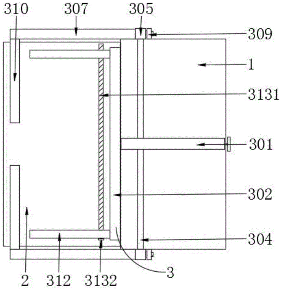
图中:1-测试装置本体、2-底板、3-定位机构、301-第一固定板、302- 第二固定板、303-调节机构、3031-活动槽、3032-第一丝杆、3033-旋转盘、 304-顶板、305-竖板、306-滑槽、307-直板、308-螺纹柱、309-紧固螺帽、310-第一卡板、311-限位机构、3111-限位槽、3112-限位块、312-第二卡板、 313-移动组件、3131-第二丝杆、3132-转动握把。In the figure: 1-test device body, 2-base plate, 3-positioning mechanism, 301-first fixed plate, 302-second fixed plate, 303-adjusting mechanism, 3031-movable groove, 3032-first screw rod, 3033 -rotary disk, 304-top plate, 305-vertical plate, 306-chute, 307-straight plate, 308-thread column, 309-fastening nut, 310-first clamping plate, 311-limiting mechanism, 3111-limiting Position slot, 3112-limiting block, 312-second clamping plate, 313-moving assembly, 3131-second screw mandrel, 3132-rotating handle.
具体实施方式detailed description
下面将结合本发明实施例中的附图,对本发明实施例中的技术方案进行清楚、完整地描述,显然,所描述的实施例仅仅是本发明一部分实施例,而不是全部的实施例。基于本发明中的实施例,本领域普通技术人员在没有做出创造性劳动前提下所获得的所有其他实施例,都属于本发明保护的范围。The following will clearly and completely describe the technical solutions in the embodiments of the present invention with reference to the accompanying drawings in the embodiments of the present invention. Obviously, the described embodiments are only some of the embodiments of the present invention, not all of them. Based on the embodiments of the present invention, all other embodiments obtained by persons of ordinary skill in the art without making creative efforts belong to the protection scope of the present invention.
请参阅图1-5,本发明提供一种技术方案:一种节能环保的动力电池电磁控制测试装置,包括测试装置本体1,测试装置本体1的一侧固定连接有底板 2,底板测试装置本体1上设置有定位机构3;定位机构3包括第一固定板301 和第二固定板302,第一固定板301固定连接在测试装置本体1的顶部上,第一固定板301上通过调节机构303活动连接有顶板304,顶板304的正面和背面均固定连接有竖板305,竖板305的一侧贯穿开设有滑槽306,竖板305的一侧滑动连接有直板307,直板307起初位于滑槽306处的最上方,直板307 的一侧固定连接有螺纹柱308,螺纹柱308的外表面螺纹连接有紧固螺帽309,直板307上固定连接有第一卡板310,第二固定板302固定连接在第二固定板 302的一侧上,第二固定板302通过限位机构311活动连接有第二卡板312,第二卡板312设置有两个,两个第二卡板312通过移动组件313活动连接,通过在第一固定板301、第二固定板302、调节机构303、顶板304、竖板305、滑槽306、直板307、螺纹柱308、紧固螺帽309、第一卡板310、限位机构 311、第二卡板312和移动组件313的配合使用下,解决了现有的测试装置与动力电池没有通过固定在一起,在人为因素下,会导致测试装置或动力电池发生位移,使得测试装置与动力电池的连接导线脱落,从而影响正常测试,降低了工作效率的问题,调节机构303包括活动槽3031,活动槽3031贯穿开设在第一固定板301的正面,活动槽3031的内部转动连接有第一丝杆3032,第一丝杆3032的一端贯穿活动槽3031并延伸至第一固定板301的外部,第一丝杆3032的一端固定连接有旋转盘3033,通过在活动槽3031、第一丝杆 3032、旋转盘3033、第二丝杆3131和转动握把3132的配合使用下,对于不同尺寸的动力电池,能够对第一卡板310和第二卡板312进行调节,有效的对动力电池进行夹持固定,使用范围广,便于使用,限位机构311包括限位槽3111和限位块3112,限位槽3111的内部与限位块3112的外表面相适配,通过在限位槽3111和限位块3112的配合使用下,在调节第二卡板312的过程中,能够提高第二卡板312运动的稳定性,限位槽3111开设在第二固定板302的一侧,限位块3112固定连接在第二卡板312的一侧,第二卡板312的底部与底板2的顶部滑动连接,第二卡板312的一侧与第二固定板302的一侧滑动连接,移动组件313包括第二丝杆3131,第二丝杆3131与第二卡板 312之间螺纹连接,第二丝杆3131的一端固定连接有转动握把3132,顶板304 的外表面与活动槽3031的内部滑动连接,直板307与测试装置本体1之间滑动连接,竖板305与测试装置本体1之间滑动连接,螺纹柱308的外表面与滑槽306的内部滑动连接。Please refer to Figures 1-5, the present invention provides a technical solution: an energy-saving and environmentally friendly power battery electromagnetic control test device, including a
同时本说明书中未作详细描述的内容均属于本领域技术人员公知的现有技术。At the same time, the content not described in detail in this specification belongs to the prior art known to those skilled in the art.
工作时,将待测试动力电池放置在底板2上面,并将待测试动力电池与测试装置本体1通过导线连接,之后,通过拧松紧固螺帽309,将直板307调节至合适的高度,之后,再将紧固螺帽309拧紧,之后,通过转动旋转盘3033,进而带动第一丝杆3032转动,在活动槽3031的限位作用下,进而带动顶板 304运动,从而带动竖板305运动,进而通过直板307带动第一卡板310运动,从而第一卡板310贴合在待测试动力电池的表面上,之后,转动转动握把3132,进而带动第二丝杆3131转动,利用限位槽3111和限位块3112的配合使用下,从而带动两个第二卡板312相对运动,从而两个第二卡板312分别贴合在待测试动力电池的表面上,从而实现对待测试动力电池进行固定,使得待测试动力电池和测试装置本体1绑定在一起,因此,解决了现有的测试装置与动力电池没有通过固定在一起,在人为因素下,会导致测试装置或动力电池发生位移,使得测试装置与动力电池的连接导线脱落,从而影响正常测试,降低了工作效率的问题。When working, place the power battery to be tested on the
需要说明的是,在本文中,诸如第一和第二等之类的关系术语仅仅用来将一个实体或者操作与另一个实体或操作区分开来,而不一定要求或者暗示这些实体或操作之间存在任何这种实际的关系或者顺序。而且,术语“包括”、“包含”或者其任何其他变体意在涵盖非排他性的包含,从而使得包括一系列要素的过程、方法、物品或者设备不仅包括那些要素,而且还包括没有明确列出的其他要素,或者是还包括为这种过程、方法、物品或者设备所固有的要素。It should be noted that in this article, relational terms such as first and second are only used to distinguish one entity or operation from another entity or operation, and do not necessarily require or imply that there is a relationship between these entities or operations. There is no such actual relationship or order between them. Furthermore, the term "comprises", "comprises" or any other variation thereof is intended to cover a non-exclusive inclusion such that a process, method, article, or apparatus comprising a set of elements includes not only those elements, but also includes elements not expressly listed. other elements of or also include elements inherent in such a process, method, article, or device.
尽管已经示出和描述了本发明的实施例,对于本领域的普通技术人员而言,可以理解在不脱离本发明的原理和精神的情况下可以对这些实施例进行多种变化、修改、替换和变型,本发明的范围由所附权利要求及其等同物限定。Although the embodiments of the present invention have been shown and described, those skilled in the art can understand that various changes, modifications and substitutions can be made to these embodiments without departing from the principle and spirit of the present invention. and modifications, the scope of the invention is defined by the appended claims and their equivalents.
Claims (8)
Priority Applications (1)
| Application Number | Priority Date | Filing Date | Title |
|---|---|---|---|
| CN202211249382.2A CN115561644A (en) | 2022-10-12 | 2022-10-12 | Energy-concerving and environment-protective power battery electromagnetic control testing arrangement |
Applications Claiming Priority (1)
| Application Number | Priority Date | Filing Date | Title |
|---|---|---|---|
| CN202211249382.2A CN115561644A (en) | 2022-10-12 | 2022-10-12 | Energy-concerving and environment-protective power battery electromagnetic control testing arrangement |
Publications (1)
| Publication Number | Publication Date |
|---|---|
| CN115561644A true CN115561644A (en) | 2023-01-03 |
Family
ID=84745786
Family Applications (1)
| Application Number | Title | Priority Date | Filing Date |
|---|---|---|---|
| CN202211249382.2A Pending CN115561644A (en) | 2022-10-12 | 2022-10-12 | Energy-concerving and environment-protective power battery electromagnetic control testing arrangement |
Country Status (1)
| Country | Link |
|---|---|
| CN (1) | CN115561644A (en) |
Cited By (1)
| Publication number | Priority date | Publication date | Assignee | Title |
|---|---|---|---|---|
| CN116558743A (en) * | 2023-07-06 | 2023-08-08 | 江苏德琛常工新能源科技创新有限公司 | Airtight testing device with leakage early warning function for hydrogen energy equipment |
Citations (5)
| Publication number | Priority date | Publication date | Assignee | Title |
|---|---|---|---|---|
| CN208140157U (en) * | 2018-05-28 | 2018-11-23 | 陈逸丹 | A kind of monitor station of power battery processing |
| CN208765933U (en) * | 2018-08-03 | 2019-04-19 | 赤峰埃晶电子科技有限公司 | A kind of Cellphone Accessories detection device |
| CN111805487A (en) * | 2020-06-22 | 2020-10-23 | 魏苒 | Fixing device is used in processing of inferior gram force panel circular arc |
| CN212540649U (en) * | 2020-06-09 | 2021-02-12 | 齐程林 | Testing arrangement of automobile power battery production usefulness |
| CN215641712U (en) * | 2021-08-13 | 2022-01-25 | 佛山市诚致金属制品有限公司 | A battery short circuit tester |
-
2022
- 2022-10-12 CN CN202211249382.2A patent/CN115561644A/en active Pending
Patent Citations (5)
| Publication number | Priority date | Publication date | Assignee | Title |
|---|---|---|---|---|
| CN208140157U (en) * | 2018-05-28 | 2018-11-23 | 陈逸丹 | A kind of monitor station of power battery processing |
| CN208765933U (en) * | 2018-08-03 | 2019-04-19 | 赤峰埃晶电子科技有限公司 | A kind of Cellphone Accessories detection device |
| CN212540649U (en) * | 2020-06-09 | 2021-02-12 | 齐程林 | Testing arrangement of automobile power battery production usefulness |
| CN111805487A (en) * | 2020-06-22 | 2020-10-23 | 魏苒 | Fixing device is used in processing of inferior gram force panel circular arc |
| CN215641712U (en) * | 2021-08-13 | 2022-01-25 | 佛山市诚致金属制品有限公司 | A battery short circuit tester |
Cited By (2)
| Publication number | Priority date | Publication date | Assignee | Title |
|---|---|---|---|---|
| CN116558743A (en) * | 2023-07-06 | 2023-08-08 | 江苏德琛常工新能源科技创新有限公司 | Airtight testing device with leakage early warning function for hydrogen energy equipment |
| CN116558743B (en) * | 2023-07-06 | 2023-09-12 | 江苏德琛常工新能源科技创新有限公司 | Airtight testing device with leakage early warning function for hydrogen energy equipment |
Similar Documents
| Publication | Publication Date | Title |
|---|---|---|
| CN204836059U (en) | Novel solar cell sunshine is tracked device | |
| CN204532715U (en) | A kind of vehicle-mounted foldable wind-force wind power equipment | |
| CN209517021U (en) | A kind of photovoltaic electric board fixer of angle adjustable | |
| CN211103583U (en) | Clamping device for lithium battery machining | |
| CN205647430U (en) | Digital solar battery array simulator | |
| CN221896737U (en) | A mounting base for wind power generation equipment | |
| CN221767957U (en) | A photovoltaic panel installation construction platform | |
| CN207510218U (en) | A kind of solar energy energy-saving and environment-friendly automobile | |
| CN218065399U (en) | Distributed fixing base for photovoltaic power generation equipment | |
| CN111404464A (en) | Folding device suitable for solar cell panel of caravan and control method thereof | |
| CN206727942U (en) | A kind of solar panels for being easy to adjust angle | |
| CN213598118U (en) | Photovoltaic power generation and wind power generation integrated device | |
| CN213752738U (en) | Photovoltaic cell piece heating platform | |
| CN221842250U (en) | Line discharge device of photovoltaic power station | |
| CN212005492U (en) | An adjustable solar street light | |
| CN114978011A (en) | Active tracking type photovoltaic support for double-sided double-glass photovoltaic system | |
| CN219304752U (en) | Photovoltaic panel support for photovoltaic power generation | |
| CN209823676U (en) | Single glass photovoltaic module installs briquetting | |
| CN220925918U (en) | Wiring device | |
| CN221755181U (en) | Frock clamp is used in wind-powered electricity generation sliding ring finish machining | |
| CN222532126U (en) | Solar cell fixing jig | |
| CN219554878U (en) | Box transformer UPS power supply device | |
| CN220043036U (en) | A charging and discharging auxiliary tool suitable for multiple models | |
| CN222134700U (en) | Wind-powered electricity generation becomes oar charger testing arrangement | |
| CN206869472U (en) | A kind of wind-driven generator lower box clamp for machining |
Legal Events
| Date | Code | Title | Description |
|---|---|---|---|
| PB01 | Publication | ||
| PB01 | Publication | ||
| SE01 | Entry into force of request for substantive examination | ||
| SE01 | Entry into force of request for substantive examination | ||
| RJ01 | Rejection of invention patent application after publication | ||
| RJ01 | Rejection of invention patent application after publication |
Application publication date: 20230103 |